Article

Research on Meshing Characteristics of Trochoidal Roller Pinion Rack Transmission

1
Shaanxi Engineering Laboratory for Transmissions and Controls, Northwestern Polytechnical University, Xi’an 710072, China
2
Shaanxi Key Laboratory of Gear Transmission, Northwestern Polytechnical University, Xi’an 710072, China
*
Author to whom correspondence should be addressed.
Appl. Sci. 2022, 12(11), 5620; https://doi.org/10.3390/app12115620
Submission received: 26 April 2022 / Revised: 26 May 2022 / Accepted: 29 May 2022 / Published: 1 June 2022
(This article belongs to the Special Issue AI Applications in the Industrial Technologies)

Abstract

:
As a precision transmission mechanism, the trochoidal roller pinion rack has been paid more and more attention in recent years, but its meshing characteristics have not been deeply explored. In order to investigate the meshing characteristics of the trochoidal roller pinion rack transmission, it is particularly important to research its line of action and meshing stiffness. The equation of the line of action of the trochoidal roller pinion rack is deduced by using its tooth profile formation principle. The motion simulation of the trochoidal roller pinion rack transmission is carried out to verify the correctness of the theoretical derivation of the equation of the line of action, and the influence of the basic parameters on the line of action is summarized. The meshing stiffness of the trochoidal roller pinion rack is calculated based on the energy method used for gear meshing stiffness, and the meshing stiffness is defined considering the time-varying characteristics of its pressure angle, and the influence of each basic parameter on the meshing stiffness is studied. The results shows that the meshing stiffness increases first and then decreases in the double tooth meshing area, while the meshing stiffness gradually decreases in the single tooth meshing area. The basic parameters including number of roller pins, the module, the rack tooth profile offset coefficient, the diameter coefficient of roller pin, and the addendum coefficient of rack have different effects on the line of action and meshing stiffness. The research conclusion can provide reference for the parameter design of the trochoidal roller pinion rack, and provide the meshing stiffness calculation method for the dynamic analysis of the transmission.

1. Introduction

The trochoidal roller pinion rack mechanism is a precision transmission device that realizes the mutual conversion of rotation and translation. Since the rack profile is trochoid, the gap in the ordinary rack and pinion transmission can be eliminated, so it can realize zero backlash transmission. In this field, KAMO SEIKO Corp. in Toyota City, Aichi County, Japan is in a leading position and has a series of mature products. Honda and Makino et al. [1,2] as pioneers in this field, have carried out a series of basic researches on cycloid roller rack transmission, involving the basic structure, transmission principle and tooth profile shape of cycloid roller rack. Sankar and Natara [3] proposed a tooth profile modification method to avoid the problem of undercutting. Ohta et al. [4] discussed the effect of coincidence on the transmission error of cycloid gears, and proposed that the use of double-row cycloid gears is an effective method to reduce the errors of cycloid gears. Gamez-Montero et al. [5] derived the normal maximum contact stress in the teeth of cycloid gears for the finite element model of quasi-static conditions to evaluate the performance of the gear set.
Zhang et al. [6,7] deduced the theoretical tooth profile equation of the rack tooth profile based on the meshing principle of the trochoidal roller pinion rack mechanism, and studied meshing force and contact stress of trochoid roller pinion rack transmission. Luo et al. [8] proposed another method to solve the problem of undercutting the root of cycloid teeth, optimizing the standard cycloid teeth into trochoid teeth with inclination, so as to obtain trochoidal roller pinion rack mechanism that can eliminate backlash. The rack of the mechanism is designed to have a certain inclination along the direction of the tooth width, and the rolling pin meshing with it is also designed to be a conical rolling pin with a corresponding inclination, so that the transmission mechanism has the advantages of automatic compensation of backlash, stable transmission and accurate positioning. Wang [9] carried out research on the contact mechanics, fatigue failure, wear failure and finite element simulation of trochoidal roller pinion rack transmission, and revealed the contact mechanics characteristics of trochoidal roller pinion rack transmission, and formed a trochoid rack reliability and service life calculation models. From the above research status, it can be seen that the current research on the trochoidal roller pinion rack is still in the early stage, and the research in many aspects is not deep enough. Efremenkov [10] studied how to reduce the cost of manufacturing the parts for gears with intermediate rolling elements and, at the same time, maintain a high accuracy of the transmission mechanism. Han [11] presented a transient hybrid EHL model for cycloidal pinwheel transmission, which takes into account key variable parameters along the meshing surface, including contact load, curvature contact radius, and entrainment speed. Li [12] take the RV cycloidal-pin gear pair transmission as the object, a meshing contact analysis method is proposed for RV cycloidal-pin gear transmission considering the influence of manufacturing error. Yang [13,14] constructed the equations of tooth profile modification to analysis the nonlinear dynamics of the TCG. Xu [15] proposes a method for analyzing the contact dynamics of the multi-tooth meshing in a cycloidal-pin gear transmission was proposed considering the influences of the turning-arm cylindrical roller bearing. The existing research on trochoidal roller pinion rack mostly focuses on the fields of load performance, optimization and manufacturing, but there is less research on its meshing characteristics.
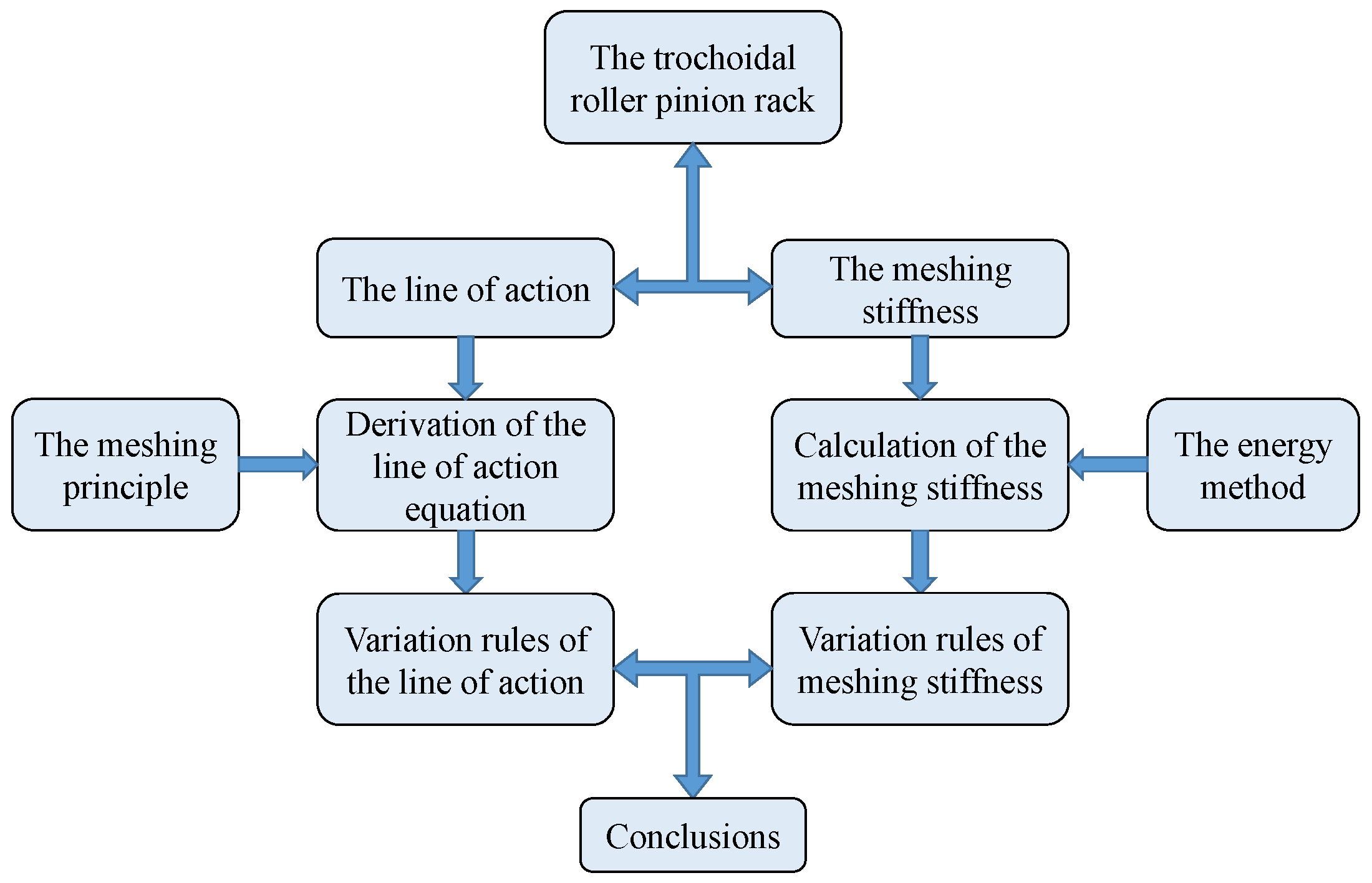
In this paper, the transmission principle of trochoidal roller pinion rack is firstly introduced, then the equation of the line of action according to the meshing principle of trochoidal roller pinion rack is deduced, and the motion of the trochoidal roller pinion rack transmission system is simulated by using Adams software. The simulation meshing point is compared with the theoretical meshing point to verify the correctness of the theoretical deduction, and the influence of each parameter on the line of action is studied. Finally, the meshing stiffness of the trochoidal roller pinion rack is defined and the meshing stiffness is calculated based on the energy method, and study the influence law of each parameter on mesh stiffness. The research content of this paper can be summarized as the flowchart shown in Figure 1. This paper innovatively deduces the equation of the line of action of the trochoidal roller pinion rack and studies its variation law, and then innovatively uses the energy method to calculate the meshing stiffness of the trochoidal roller pinion rack and study its variation law.
So far, the research on trochoidal roller pinion rack is still at the stage of basic principle, and further research on it is of great significance to its development. Further research is of great significance to its development. Section 3 of this paper deduces its equation of the line of action based on the meshing principle of trochoidal roller pinion rack. Since this equation is deduced for the first time, the simulation method is used to verify its correctness in Section 4. Section 5 uses the energy method used for gear mesh stiffness to calculate the mesh stiffness of the trochoidal roller pinion rack. This mesh stiffness calculation is only used as a reference for the follow-up research, and its verification will be carried out in the follow-up research.

2. Transmission Principle of Trochoidal Roller Pinion Rack

The trochoidal roller pinion rack is a transmission device that can convert linear motion into rotational motion. The structure of the roller pinion rack is shown in Figure 2, and the whole mechanism consists of three parts: 1 rack, 2 roller pinion, 3 roller pin. The tooth profile of the rack is trochoid, and several circular holes are evenly distributed on the circumference, and the roller pins are cylinder installed in the evenly distributed circumferential holes of the roller pinion. The rack has a linear motion state as the driving element, the rack and the roller pins transmit the linear motion to the roller pinion through meshing, and the roller pinion as the output element has a rotational motion around its axis.
Figure 2b shows a schematic diagram of each parameter in the trochoidal roller pinion rack, the meaning and calculation method of each parameter are shown in Table 1.
The characteristic of the trochoidal roller pinion rack with no backlash in both directions is mainly due to its special meshing state. Figure 3 is schematic diagram of the meshing state. As shown in the Figure 3, the pitch circle of the roller pinion is tangent to the pitch line of the rack during the meshing process. In the static state, the meshing points a, b, and c are all in contact with the rack. When the rack moves to the left, the meshing point is a, b. When the rack moves to the right, the meshing points are b and c. Because of its unique meshing characteristics, it has the characteristics of bidirectional movement without backlash.

3. Equations of Line of Action

Some scholars have studied the line of action of gears for a long time. The research results show that the line of action of the gear is a straight line, which is the internal common tangent of the base circle of the two gears. There is no research on the line of action of the trochoidal roller pinion rack, so this section first deduces the equation of line of action. The determination of the line of action of the trochoidal roller pinion rack needs to be analyzed from the formation process of its tooth profile. Reference [6] carried out a detailed study of the trochoid rack tooth profile, and its meshing principle and tooth profile equation have been studied. This paper further studies the line of action of the trochoid roller pinion rack on the basis of reference [6]. The meshing principle is used to deduce the equations of the line of action, but since no scholars have studied the line of action of the trochoid roller pinion rack before, in order to prove the correctness of the derivation of the equation of the line of action in this paper, in Section 4 of this paper, kinematics simulation of the trochoid roller pinion rack is carried out to prove the correctness of the theoretical derivation. 
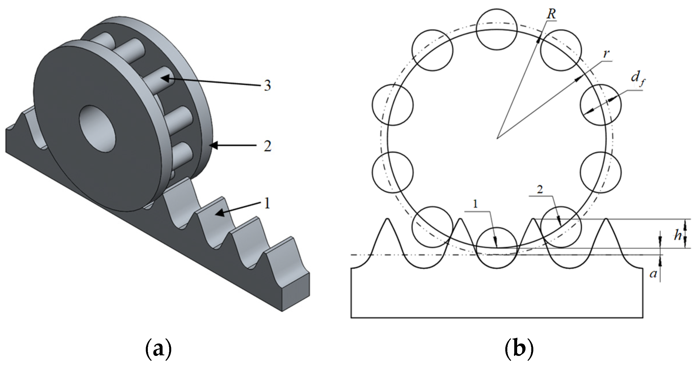
Figure 4 is the schematic diagram of the formation of the trochoid rack tooth profile [6]. As shown in the Figure 4, the rack pitch line is the x-axis, and the tooth profile symmetry axis is the y-axis to establish a coordinate system. r is the radius of the reference circle of the roller pinion, R is the radius of the pitch circle of the roller, Oc is the center of the two circles, and the initial position of Oc is on the y-axis. The pitch circle of the roller rolls along the x-axis, then the path traversed by a point M’ on the reference circle of the roller pinion is the theoretical tooth profile of the trochoid, the curve formed by a point N’ that is apart from the normal direction of the theoretical tooth profile by rf is the actual tooth profile of the trochoid rack. The point N’ is also the meshing point at a certain moment of meshing. When considering the movement of the roller pinion and rack, the line formed by the meshing point N’ at each moment during the movement of the trochoid roller pinion rack is the line of action. According to the meshing characteristic that the meshing point must be on the straight line formed by the center of the meshing roller pin and the pitch node, the equation of line of action is deduced in this paper.
The coordinate system is established as shown in Figure 5, the origin O of the coordinate system is the pitch node, the X-axis is the moving direction of the rack, and the Y-axis passes through the center of the roller pinion. When the rotation angle of the roller pinion is φ, its meshing state is shown in Figure 5. Point A is the center of the meshing roller pin, point B is the intersection of point A and the X-axis, point D is the meshing point, and point C is the intersection of point D and the X-axis. The triangle ODC is similar to the triangle OAB, so these line segments satisfy the relationship of Equation (1).
O C ¯ O B ¯ = D C ¯ A B ¯ = O D ¯ O A ¯
It can be seen from Figure 5 that the length of O B ¯ is the absolute value of abscissa of point A, the length of A B ¯ is the value of ordinate of point A, the length of O C ¯ is the absolute value of abscissa of point D, and the length of D C ¯ is the value of ordinate of point D. Since point A is on the reference circle of the roller pinion, the coordinate value of point A can be expressed by Equations (2).
{ x A = m z 2 sin φ y A = m z 2 + m c y + m z 2 cos φ
The length of A O ¯ can be obtained from the triangle OAB according to the coordinates of point A, and the length of A D ¯ is the radius of the roller pin, so the Equation (1) can be changed to Equation (3).
x D m z 2 sin φ = y D m z 2 + m c y m z 2 cos φ = x A 2 + y A 2 m c f 2 x A 2 + y A 2
According to Equation (3), the coordinate equations of the meshing point D are derived as Equations (4).
{ x D = m z 2 sin φ ( m z 2 sin φ ) 2 + ( m z 2 + m c y m z 2 cos φ ) 2 m c f 2 ( m z 2 sin φ ) 2 + ( m z 2 + m c y m z 2 cos φ ) 2 y D = ( m z 2 + m c y m z 2 cos φ ) ( m z 2 sin φ ) 2 + ( m z 2 + m c y m z 2 cos φ ) 2 m c f 2 ( m z 2 sin φ ) 2 + ( m z 2 + m c y m z 2 cos φ ) 2
The above process is the derivation of the theoretical equation of line of action, but the line of action has a certain length in the actual meshing process. During the meshing process of the roller pins and the rack, the roller pins engage from the root of the tooth and mesh out at the top of the tooth, so the calculation of the actual length of line of action is actually the calculation of the position of the meshing in and meshing out. In this paper, the meshing in point and meshing out point are defined by the rotation angle of the roller pinion, and the meshing in point at the root of the tooth is defined in this paper to be 0°, and the meshing out point at the top of the tooth is φh. Figure 6 is the schematic diagram of the meshing in point and meshing out point. The solid line is the meshing situation at the beginning of meshing. Point 1 is the meshing in point, at this time, the angle of the roller pinion is 0°, and the dotted line is the meshing situation at the ending of meshing, and point 2 is the meshing out point, at this time, the rotation angle of the roller pinion is φh.
The calculation of the rotation angle of the roller pinion at the meshing point 2 also needs to be analysed from the formation principle of the trochoid profile. The meshing process of the roller pinion and the rack is actually the formation process of the trochoid rack tooth profile. Figure 7 shows the position of the roller pin when the roller pin is out of engagement. XOY is the coordinate system during meshing, which coincides with the X-axis in Figure 5. The difference is that the coordinate system is moving relative to the rack, but the coordinate value in the Y-axis direction is the same as the value when the tooth profile is formed. The value of Y-axis coordinate of the meshing out point is h + a.
The profile equations of the trochoid rack are Equations (5) [6]. According to the above analysis and the coordinate equations of the trochoid profile, the roller pinion angle φh can be obtained by Equation (6).
{ x = ( m z 2 + m c y ) φ m z 2 sin φ + m z c f sin φ 4 ( z 2 + c y ) 2 ( z 2 + c y ) z cos φ + ( z 2 ) 2 y = m z 2 + m c y m z 2 cos φ m c f 2 ( z 2 + c y z 2 cos φ ) ( z 2 + c y ) 2 ( z 2 + c y ) z cos φ + ( z 2 ) 2
m c h + m c y = m z 2 + m c y m z cos φ h 2 m c f 2 ( z 2 + c y z 2 cos φ h ) ( z 2 + c y ) 2 ( z 2 + c y ) z cos φ h + ( z 2 ) 2
The parameters of the trochoidal roller pinion rack are shown in Table 2. Figure 8 is the curve of the line of action drawn according to Equations (4) and (6).
It can be seen from Figure 8 that the line of action of the trochoid roller pinion rack is quite different from that of gear pair. The line of action of gear pair is a straight line, while the line of action of the trochoid roller pinion rack is a curve. Marks of 1, 2, 3, 4, and 5 in Figure 7 are five special points. There have two intersection points where the X-axis coordinate is equal to 0, which are point 1 and point 3. Point 1 is the start of meshing, and point 3 is above point 1. Point 2 is the limit position of the right end of the line of action. point 4 is the point where the next roller pin starts to enter meshing, at that moment the next roller pin is at the point 1 of the line of action. point 5 is the point where the roller pin meshes out from the tooth top.

4. Verification and Variation Rules of the Line of Action

The kinematics simulation of the trochoid roller pinion rack will be performed by using the motion simulation software Adams to verify aforementioned equations of the line of action of the trochoid roller pinion rack.

4.1. Verification of the Equation of the Line of Action

The values of roller pinion angle and rack moving distance for the five special points of Figure 8 according to the theoretical formula are calculated. The theoretical calculated results of the five points are shown in Table 3.
The trochoid roller pinion rack is modelled in 3D according to the parameters data in Table 2, and kinematics is simulated by using Adams. The moving pair is applied to the rack, the rotating pair is applied to the roller pinion, the drive is applied to the rack moving pair with a speed of 20 mm/s, the contact force is set between the rack and the roller pins, and the simulation time is set to 5 s. The number of steps is set to 1000, and the simulation results are shown as following.
Figure 9 shows the meshing situation at the beginning of the simulation, which corresponds to point 1 in Figure 8. The green roller pin is defined as a, the black roller pin is defined as b, and the black vertical line is defined as the line with the X-axis (horizontal axis) coordinate value of 0 in Figure 7, its position is fixed. At this time, the rolling pin a begins to engage.
Figure 10 corresponds to the simulation result of point 2 in Figure 8. The number of simulation steps at this time is the 32nd. Since the total number of steps is 1000, the moving distance of the rack is 3.2000 mm at this moment, and the corresponding roller pinion angle is 3.0558°.
Figure 11 corresponds to the simulation result of point 3 in Figure 8. The number of simulation steps at this time is the 65nd. The moving distance of the rack is 6.5000 mm at this moment, and the corresponding roller pinion angle is 6.2070°.
Figure 12 corresponds to the simulation result of point 4 in Figure 8. The number of simulation steps at this time is the 380nd. The moving distance of the rack is 38.000 mm at this moment, and the corresponding roller pinion angle is 36.2873°.
Figure 13 corresponds to the simulation result of point 5 in Figure 8. The number of simulation steps at this time is the 529nd. The moving distance of the rack is 52.900 mm at this moment, and the corresponding roller pinion angle is 50.5158°.
According to the simulation results, the theoretical calculation values of the actual line of action and the errors of the simulation results for the five special points are calculated as shown in Table 3. It can be seen that the theoretical value of the line of action calculated by the formula and the value obtained by the software simulation have errors within 1%, so it can be proved that the derivation of the equation of the line of action of the trochoid roller pinion rack in this paper is correct. According to the variance calculation method, the rack simulation uncertainty is 0.0189 and the roller simulation uncertainty is 0.0172.

4.2. Variation Rules of the Line of Action

Since the line of action of the trochoidal roller pinion rack is a curve, it is of great significance to study how each parameter affects the line of action. The following mainly studies the influence of the number of roller pins z, the module m, the diameter coefficient of roller pin cf, the addendum coefficient of rack ch, and the rack tooth profile offset coefficient cy on the line of action.
The influence law of the number of roller pins z on the line of action is shown in Figure 14. It can be seen that the change of z has no effect on the starting point of the line of action but has a certain influence on the end point. The abscissa of the end point of the line of action decreases with the increase of z, and the length of the line of action increases with the increase of z.
The influence law of the module m on the line of action is shown in Figure 15. It can be seen that the change of m has a certain influence on the start and end points of the line of action. The ordinate of the starting point of the line of action decreases with the increase of m, the abscissa of the end point of the line of action decreases with the increase of m, the ordinate of the end point of the line of action increases with the increase of m, and the length of the line of action increases with the increase of m.
The influence law of the diameter coefficient of roller pin cf on the line of action is shown in Figure 16. It can be seen that the change of cf has a certain influence on the start and end points of the line of action. The ordinate of the starting point of the line of action decreases with the increase of cf, the abscissa of the end point of the line of action increases with the increase of cf, and the length of the line of action increases with the increase of cf.
The influence law of the addendum coefficient of rack ch on the line of action is shown in Figure 17. It can be seen that the ch only affects the length of the line of action. The three different line types with marks represent different values of ch, and the length of the line of action increases with the increase of ch.
The influence law of the rack tooth profile offset coefficient cy on the line of action is shown in Figure 18. It can be seen that the change of ch has a certain influence on the start and end points of the line of action. The ordinate of the starting point of the line of action increases with the increase of cy, the abscissa of the end point of the line of action decreases with the increase of cy, and the ordinate of the end point of the line of action increases with the increase of cy. The length of the line of action increases with the increase of cy.

5. The Meshing Stiffness of the Trochoid Roller Pinion Rack

For gear pair, the calculation of meshing stiffness has an extremely important position, and the calculation of meshing stiffness has also formed some relatively mature methods, such as the material mechanics method [16], the conformal mapping method [17], the finite element method [18], the loaded tooth contact analysis method [19], the energy method [20], etc. For the trochoid roller pinion rack transmission, there is no mature method and result for calculating its meshing stiffness. In this paper, the meshing stiffness of trochoid roller pinion rack is theoretically calculated by referring to the energy method of gear pair, and the influence laws of each parameter on meshing stiffness are studied.
The research on meshing stiffness plays an important role in dynamics research. As a new type of precision machinery, the meshing stiffness of the trochoid roller pinion rack are still blank. In this section, the meshing stiffness of the trochoid roller pinion rack is theoretically calculated with reference to the energy method used for the calculation of gear meshing stiffness. Since the teeth of the gear and the teeth of the trochoid rack have similar characteristics, this paper uses the energy method in reference [21] to replace the gear model with the rack model to calculate its meshing stiffness. This paper only proposes its meshing stiffness calculation method as a reference for follow-up research, its experimental verification will continue in follow-up research.

5.1. Definition of Meshing Stiffness of Trochoidal Roller Pinion Rack

The meshing stiffness of gear pair is in the normal direction of the line of action. The line of action of the gear pair is a straight line and the pressure angle does not change during the transmission process. However, the pressure angle of the trochoid roller pinion rack changes with time as shown in Figure 19. The interval 1 is a meshing period, the interval 2 is the double-tooth meshing interval, and the interval 3 is the single-tooth meshing interval. It can be seen that the pressure angle of the meshing point of the two roller pins in the double-tooth meshing interval is quite different. This meshing characteristic is different from the fixed pressure angle of the gear. In the traditional gear transmission, the meshing stiffness of the double-tooth meshing area is the direct superposition of the meshing stiffness of the two meshing points, but it cannot be fully applied to the trochoidal roller pinion rack.
Since the output of the trochoid roller pinion rack is a circular motion, it is more practical to convert the meshing stiffness into the torsional stiffness on the roller pinion. The meshing stiffness krp of the trochoid roller pinion rack is defined as the torque value required for the roller pinion to produce 1 rad torsional deformation, which is the deformation of the tangential direction of the meshing point converted to the deformation on the roller pinion. The pressure angle of the two meshing points in the double-tooth meshing area of the trochoid roller pinion rack is quite different, and the normal direction of the meshing point is not the same as the tangential direction of the roller pinion where the meshing point is located. Therefore, it is necessary to convert the meshing stiffness at the two meshing points during calculation. The normal meshing stiffness k of the meshing point is calculated by the energy method, and then it is first converted into the tangential meshing stiffness kt of the roller pinion, and then kt is converted into the torsional meshing stiffness krp of the roller pinion. The conversion method between the stiffnesses is described as following.
As shown in Figure 20, Di represents the i-th (i = 1,2) meshing point, O is the pitch node of the rack, DiO represents the force direction at the meshing point Di, and li represents the tangent direction of the meshing point Di on the roller pinion direction, and θi represents the angle between the force direction and the tangent direction of the meshing point Di, Ri represents the distance between the meshing point Di and the O’ which is the center of the roller pinion. Using the energy method, the meshing stiffness ki of Di can be directly calculated, the normal meshing stiffness ki is in the DiO direction. The meshing stiffness of the two meshing points is superimposed as the system normal meshing stiffness k. The calculation method of the tangential meshing stiffness kt of the trochoid roller pinion rack is shown in Equation (7), and the calculation method of the meshing stiffness krp is shown in Equation (8).
k t = k cos ( θ i )
k r p = k t R i 2

5.2. Calculation of the Stiffness of Each Component

The energy method is used to calculate the normal meshing stiffness of the trochoid roller pinion rack [21]. The hertzian contact potential energy Uh, bending potential energy Ub, shear potential energy Us, and axial compression potential energy Ua during the meshing process are mainly considered. The relationship between these potential energy and stiffness is shown in Equation (9) [21].
U i = F 2 2 k i
where F is the static normal meshing force at the meshing point, Ui (i = h, b, s, a) is the potential energy existing in meshing, and ki(i = h, b, s, a) is the stiffness corresponding to each potential energy.
The total energy stored in a pair of meshing pairs is shown in Equation (10) [21]. In the Equation (10), subscripts 1 and 2 represent rack and roller pinion respectively. Equation (11) [21] is used to calculate the normal stiffness at the meshing point. Since the rack of the roller pinion is engaged alternately with single and double tooth, the meshing stiffness in the normal direction of time variation in the whole meshing is Equation (12).
U = U h + U b 1 + U s 1 + U a 1 + U f 1 + U b 2 + U s 2 + U a 2 + U f 2 = F 2 2 ( 1 k h + 1 k b 1 + 1 k s 1 + 1 k a 1 + 1 k f 1 + 1 k b 2 + 1 k s 2 + 1 k a 2 + 1 k f 2 )
k = 1 1 k h + 1 k b 1 + 1 k s 1 + 1 k a 1 + 1 k f 1 + 1 k b 2 + 1 k s 2 + 1 k a 2 + 1 k f 2
k = i = 1 2 1 1 k h + 1 k b 1 , i + 1 k s 1 , i + 1 k a 1 , i + 1 k f 1 , i + 1 k b 2 , i + 1 k s 2 , i + 1 k a 2 , i + 1 k f 2 , i
where i (i = 1, 2) is the ith engagement pair.
There is a formula relationship between energy and each component stiffness. The force exerted on a certain instant of the rack in the meshing process is shown in Figure 21, where α is the meshing pressure angle.
Bending energy, shear energy and axial compression energy can be obtained according to the material mechanics method, and can be expressed as Equations (13)–(15) [21] respectively.
U b = 0 d M 2 2 E I x d s
U s = 0 d 1.2 F b 2 2 G A x d s
U a = 0 d F a 2 2 E A x d s
where, Fb = Fcosα, Fa = Fsinα, M = FbxFah, d is the height between the force point and the tooth root which is shown in Figure 20.
The bending deformation flexibility of the rack in the meshing process can be expressed as Equation (16) [21].
δ b = 0 d ( s cos α h sin α ) 2 E I x d s
The shear deformation flexibility of the rack is expressed in Equation (17) [21].
δ s = 0 d 1.2 cos 2 α G A x d s
The axial compression deformation flexibility of the rack is expressed in Equation (18) [21].
δ a = 0 d sin 2 α E A x d s
The contact deformation flexibility of the rack is expressed in Equation (19) [21].
δ h = 4 ( 1 ν 2 ) π E L
where, E is the elastic modulus of material, G is the shear modulus of material, G = E/2(1 + ν), Ix is the moment of inertia of the section at the meshing point M, Ix = 2/3hx3L, Ax is the cross section area at the meshing point M, Ax = 2hxL, ν is the poisson’s ratio of material, L is the tooth width of rack.
The rotation angle of the roller pinion corresponding to the meshing point M is φM, and the coordinates at the meshing point M(xM, yM) can be calculated according to the rotation angle φM at point M by using Equation (5).
The calculation method of meshing pressure angle α at the meshing point is shown in Equation (20) [6].
α = arcsin z 2 + c y z cos φ 2 ( z 2 + c y ) 2 + ( z 2 ) 2 ( z 2 + c y ) z cos φ
Since the coordinate of the trochoidal rack tooth profile curve is derived according to the rotation angle φ of the roller pinion, the φ is also integrated in the calculation of flexibility, which needs to use the substitution method to replace the above various parameters with the φ. Each parameter can be expressed by the rotation angle φ of the roller pinion through Equations (21)–(24).
d = r f m c y + y M
h = 0.5 p x M
h x = 0.5 p x
s = y M y
where p is the pitch of the rack.
Through the substitution method, the calculation methods of each deformation flexibility of the rack are shown in Equations (25)–(28).
δ b 1 = 0 φ M [ ( y M y ) cos α ( p 2 x M ) sin α ] 2 2 3 E ( p 2 x ) 3 L ( y ˙ ) d φ
δ s 1 = 0 φ M 1.2 cos 2 α 2 G ( p 2 x ) L ( y ˙ ) d φ
δ a 1 = 0 φ M sin 2 α 2 E ( p 2 x ) L ( y ˙ ) d φ
δ h = 4 ( 1 ν 2 ) π E L
As for the stiffness calculation of the roller pinion, since the roller pin is cylindrical and the meshing force direction always passes through the center of the circle in the meshing process, the roller pin stiffness can be approximately considered as a constant value.
The bending deformation flexibility of the roller pinion is expressed in Equation (29).
δ b 2 = 4 ( L r 3 + L 3 8 L 2 L r 2 ) 3 π E d f 4
where Lr is the width of the roller pinion.
The shear deformation flexibility of the roller pinion is expressed in Equation (30).
δ s 2 = 0 L 1.2 2 G L d f d x
The axial compression deformation flexibility of the roller pinion is expressed in Equation (31).
δ a 2 = 2 0 r f d f E L r f 2 x 2 d x

5.3. Calculation of Time-Varying Meshing Stiffness

As the deformation flexibility and stiffness are reciprocal, the normal meshing stiffness of the trochoidal roller pinion rack with double tooth meshing is expressed in Equation (32).
k = i = 1 2 1 δ h + δ b 1 , i + δ s 1 , i + δ a 1 , i + δ b 2 , i + δ s 2 , i + δ a 2 , i
Figure 22 shows the meshing situation of trochoidal roller pinion rack with double tooth meshing. The meanings of each parameter are the same as those in Figure 19. Because the force direction of the meshing point is not consistent with the tangential direction, so the meshing stiffness in the normal direction needs to be converted to the tangential direction of the roller pinion, and the meshing stiffness in the tangential direction of the roller pinion is calculated by Equation (33).
k t = i = 1 2 cos θ i δ h + δ b 1 , i + δ s 1 , i + δ a 1 , i + δ b 2 , i + δ s 2 , i + δ a 2 , i
The triangle D2OO’ in Figure 18, D2 is the meshing point, its coordinate equation is Equation (5). O is the origin (0, 0), The O’ coordinate is (0, R). Angle OD2O’ can be calculated by using the cosine theorem in the triangle, and the calculation method of angle θi can be calculated by Equation (34).
θ i = | π 2 arccos ( ( x D 2 + y D 2 ) + ( x D 2 + ( R y D ) 2 ) R 2 2 x D 2 + y D 2 x D 2 + ( R y D ) 2 ) |
The distance between the meshing point and the center of the roller pinion changes at different meshing moments, as shown in Figure 21. The meshing radius R1 is D1O’ at point D1, and the meshing radius R2 is D2O’ at point D2. The meshing stiffness in the tangential direction of the meshing point kt is transformed into the meshing stiffness of the trochoidal roller pinion rack krp by Equation (35).
k r p = i = 1 2 cos ( θ i ) R i 2 ( δ h + δ b 1 , i + δ s 1 , i + δ a 1 , i + δ b 2 , i + δ s 2 , i + δ a 2 , i )
The calculation method of Ri is shown in Equation (36).
R i = x D 2 + ( R y D 2 )
The meshing stiffness per tooth width of the trochoidal roller pinion rack can be obtained by calculating the parameters of the trochoidal roller pinion rack shown in Table 4, as shown in Figure 23. The meshing stiffness curve is the time-varying meshing stiffness curve of a roller pin in the whole process from entering meshing to leaving meshing.
The meshing stiffness in Figure 23 shows the dividing line of single tooth and double tooth meshing area. That is double tooth meshing area at the beginning of meshing, at this point the second roller pin has just started to enter the mesh, the meshing stiffness of double tooth meshing area increases first and then decreases. The reason for the low meshing stiffness at the starting point is that the angle θ1 is large at the beginning of double tooth meshing area, as shown in Figure 22, therefore, the value of meshing point D1 stiffness converted to tangent direction is very small, so the meshing point does not play an important role in meshing, and the force is mainly borne by D2. With the rotation of the roller, the value of θ1 will gradually decrease, resulting in the increase of meshing stiffness. Then, as the rotation angle of the roller pinion continues to increase, the position of the meshing point on the rack gradually moves up. At this time, the tooth thickness at the meshing point of the rack gradually decreases, resulting in the meshing stiffness decreases again. As the roller angle continues to increase, a roller pin will disengage and the engagement becomes a single tooth engagement. In the meshing region of single tooth, the position of meshing point on the rack gradually moves up with the increase of roller angle. Then the tooth thickness at the meshing point of the rack gradually decreases, leading to the decrease of meshing stiffness. Finally, the next roller pin comes into meshing and becomes double tooth meshing area for the next meshing cycle.

6. Variation Rules of Meshing Stiffness

There are five basic parameters in the trochoidal roller pinion rack, including the number of roller pins z, the module m, the rack tooth profile offset coefficient cy, the addendum coefficient of rack ch, and the diameter coefficient of roller pin cf. In this paper, the influences of each parameter on meshing stiffness are studied by using control variable method. The five basic parameters are calculated according to the data in Table 2.

6.1. Influence of the Number of Roller Pins z

The number of roller pins z is set as 10, 11 and 12. The results are shown in Figure 24. It can be seen that the meshing stiffness of the trochoidal roller pinion rack increases with the increase of z. The main reason is that with the increase of z, the radius of the roller pinion increases, leading to the increase of torsional meshing stiffness. In addition, with the increase of z, the proportion of the double tooth meshing area also increases.

6.2. Influence of the Module m

The module m is set as 7.5 mm, 8.0 mm and 8.5 mm. The results are shown in Figure 25. It can be seen that the meshing stiffness of the trochoidal roller pinion rack increases with the increase of m. The main reason is that with the increase of m, the radius of the roller pinion increases, leading to the increase of torsional meshing stiffness. The modulus has no effect on the meshing area.

6.3. Influence of the Rack Tooth Profile Offset Coefficient cy

The rack tooth profile offset coefficient cy is set as 0.305, 0.405 and 0.505. The results are shown in Figure 26. It can be seen that the influence of cy on meshing stiffness is mainly on the double tooth meshing area. In the double tooth meshing area, the meshing stiffness decreases with the increase of the cy, and in the single tooth meshing area, the meshing stiffness increases with the increase of the cy, but the influence in the single tooth meshing area is small. In addition, the proportion of the double tooth meshing area increases slightly with the increase of the cy.

6.4. Influence of the Addendum Coefficient of Rack ch

The addendum coefficient of rack ch is set as 1.233, 1.283 and 1.333. The results are shown in Figure 27. It can be seen that the ch has basically no influence on the meshing stiffness, but the ch has a great influence on the proportion of the single ang double tooth meshing area, the proportion of the double tooth meshing area increases with the increase of the ch.

6.5. Influence of the Diameter Coefficient of Roller Pin cf

The diameter coefficient of roller pin cf is set as 1.867, 1.917 and 1.967. The results are shown in Figure 28. It can be seen that the cf mainly affects the meshing stiffness. The meshing stiffness in both the single tooth meshing area and the double tooth meshing area increase with the increase of the cf. In addition, the proportion of the double tooth meshing area increases slightly with the increase of the cf.

7. Shortcomings and Prospects

The derivation of the line of action equation of the trochoidal roller pinion rack in the article is a theoretical derivation based on the meshing principle. In this paper, only the simulation verification is carried out, but the experimental verification is not carried out. The follow-up research can carry out experimental verification to further prove the derivation in this paper. In this paper, only the energy method is used for the theoretical calculation of meshing stiffness without verification, and subsequent research can use other methods to calculate it and also carry out experimental verification.
The research on the line of action equation in this paper can help to further understand the meshing principle and characteristics of the trochoidal roller pinion rack. The calculation of mesh stiffness can be used for subsequent trochoid roller rack dynamics studies.

8. Conclusions

(1)
In this paper, the line of action of trochoidal roller pinion rack is firstly studied, and the equations of the line of action are deduced by using its tooth profile formation principle and meshing characteristics. It is found that the line of action of trochoidal roller pinion rack is a curve, not a straight line.
(2)
The kinematics simulation is carried out by Adams software, and the positions of five special meshing points are extracted and compared with the theoretical values. The error is less than 1%, which proves the correctness of the equations of the line of action.
(3)
It is found that the number of roller pins z and the module m have influences on the end point and length of the line of action. The rack tooth profile offset coefficient cy and the diameter coefficient of roller pin cf have influences on the start point, end point and length of the line of action. The addendum coefficient of rack ch only affects the length of the line of action.
(4)
The calculation formula of meshing stiffness per unit tooth width of the trochoidal roller pinion rack is derived. Since the trochoidal roller pinion rack has time-varying pressure angle, its meshing stiffness is transformed into torsional stiffness of the roller pinion. The meshing stiffness is obviously divided into single tooth meshing area and double tooth meshing area. In the double tooth meshing area, the meshing stiffness increases first and then decreases, while in the single tooth meshing area, the meshing stiffness gradually decreases.
(5)
The number of roller pins z has influence on the value of meshing stiffness and the meshing range of single and double tooth meshing areas. The module m and the rack tooth profile offset coefficient cy mainly affect the value of meshing stiffness. The diameter coefficient of roller pin cf has influence on the value of meshing stiffness and the meshing range of double tooth meshing areas. The addendum coefficient of rack ch only affects the meshing range of single and double tooth meshing areas.

Author Contributions

Conceptualization, G.L.; methodology, H.W.; computation and analysis, L.L.; writing—original draft preparation, L.L.; writing—review and editing, H.W. All authors have read and agreed to the published version of the manuscript.

Funding

This research was funded by the National Key Research and Development Plan of China (2019YFB2004700).

Conflicts of Interest

The authors declare no conflict of interest.

References

  1. Honda, H.; Making, H. Research on the trochoidal gears (1st report). J. Jpn. Soc. Precis. Eng. 1994, 60, 949–953. [Google Scholar] [CrossRef] [Green Version]
  2. Honda, H. Research on the trochoidal gears (2nd report). J. Jpn. Soc. Precis. Eng. 1995, 61, 208–212. [Google Scholar] [CrossRef] [Green Version]
  3. Shanmugasundaram, S.; Muthusamy, N. Profile modification—A design approach for increasing the tooth strength in spur gear. Int. J. Adv. Manuf. Technol. 2011, 55, 1–10. [Google Scholar]
  4. Hiroyuki, O.; Kengo, K.; Masahumi, K. Effects of contact ratio on transmission errors of trochoidal gears. J. Tribol. 2014, 136, 031101. [Google Scholar]
  5. Gamez-montero, P.J.; Castilla, R.; Khamashta, M.; Codina, E. Contact problems of a trochoidal-gear pump. Int. J. Mech. Sci. 2006, 48, 1471–1480. [Google Scholar] [CrossRef]
  6. Zhang, P.; Zhang, Y.; Zhang, Y.H.; Bao, B.B. Research on tooth profile synthesis of trochoidal roller pinion rack transmission. Mech. Sci. Technol. Aerosp. Eng. 2017, 36, 722–728. [Google Scholar]
  7. Zhang, Y.; Zhang, P.; Bao, B. Research of mechanical property of trochoid roller pinion rack transmissions. J. Mech. Transm. 2016, 40, 27–31. [Google Scholar]
  8. Luo, P. Basic Theoretical Analysis of Anti-Backlash Rolling Pin-Trochoid Gear Transmission. Master’s Thesis, Beijing University of Technology, Beijing, China, 2014. [Google Scholar]
  9. Wang, Z.M. Research on Contact Mechanics and Life Criterion of Trochoidal Roller Pinion Rack Transmission. Master’s Thesis, Anhui University of Technology, Maanshan, China, 2020. [Google Scholar]
  10. Efremenkov, E.A.; Martyushev, N.V.; Skeeba, V.Y. Research on the possibility of lowering the manufacturing accuracy of cycloid transmission wheels with intermediate rolling elements and a free cage. Appl. Sci. 2022, 12, 5. [Google Scholar] [CrossRef]
  11. Han, J.; Li, W.; Qiao, Z. Analysis of mixed lubrication characteristics of cycloid pin-wheel transmission. Int. J. Precis. Eng. Manuf. 2021, 22, 453–472. [Google Scholar] [CrossRef]
  12. Li, T.; Tian, M.; Xu, H.; Deng, X.; An, X.; Su, J. Meshing contact analysis of cycloidal-pin gear in RV reducer considering the influence of manufacturing error. J. Braz. Soc. Mech. Sci. Eng. 2020, 42, 133. [Google Scholar] [CrossRef]
  13. Yang, R.; Han, B.; Xiang, J. Nonlinear dynamic analysis of a trochoid cam gear with the tooth profile modification. Int. J. Precis. Eng. Manuf. 2020, 21, 2299–2321. [Google Scholar] [CrossRef]
  14. Yang, R.; Han, B.; Li, F.; Zhou, Y.; Xiang, J. Nonlinear dynamic analysis of a trochoid cam gear. J. Mech. Des. 2020, 142, 094502. [Google Scholar] [CrossRef]
  15. Xu, L.; Yang, Y. Dynamic modeling and contact analysis of a cycloid-pin gear mechanism with a turning arm cylindrical roller bearing. Mech. Mach. Theory 2016, 104, 327–349. [Google Scholar] [CrossRef]
  16. Weber, C. The Deformations of Loaded Gears and the Effect on Their Load-Carrying Capacity; Report No. 3; Department of Scientific and Industrial Research: London, UK, 1949. [Google Scholar]
  17. Terauchi, Y.; Nagamura, K. Study on deflection of spur gear teeth (2nd report). Bull. JSME 1981, 24, 447–452. [Google Scholar] [CrossRef]
  18. Sandeep, V. A combined surface integral and finite element solution for a three-dimensional contact problem. Int. J. Numer. Methods Eng. 1991, 31, 525–545. [Google Scholar]
  19. Fang, Z.D. Models and methods for the loaded tooth contact analysis (LTCA). Mech. Transm. 1998, 22, 1–4. [Google Scholar]
  20. Yang, D.C.H.; Lin, J.Y. Hertzian damping, tooth friction and bending elasticity in gear impact dynamics. J. Mech. Des. 1987, 109, 189–196. [Google Scholar] [CrossRef]
  21. Wu, S. Gearbox Dynamic Simulation and Estimation of Fault Growth. Ph.D. Thesis, University of Alberta, Edmonton, AB, Canada, 2007. [Google Scholar]
Figure 1. The flowchart of research content.
Applsci 12 05620 g001
Figure 2. Trochoidal roller pinion rack: (a) Schematic diagram of the structure; (b) Schematic diagram of the parameters.
Applsci 12 05620 g002
Figure 3. Schematic diagram of meshing of trochoidal roller pinion rack.
Applsci 12 05620 g003
Figure 4. Schematic diagram of the formation of trochoid rack tooth profile.
Applsci 12 05620 g004
Figure 5. Schematic diagram of meshing point of trochoid roller pinion rack.
Applsci 12 05620 g005
Figure 6. Schematic diagram of the meshing in and out points of the trochoid roller pinion rack.
Applsci 12 05620 g006
Figure 7. Schematic diagram of the moment when the roller pin is out of engagement.
Applsci 12 05620 g007
Figure 8. Schematic diagram of the line of action.
Applsci 12 05620 g008
Figure 9. Simulation result of point 1.
Applsci 12 05620 g009
Figure 10. Simulation result of point 2.
Applsci 12 05620 g010
Figure 11. Simulation result of point 3.
Applsci 12 05620 g011
Figure 12. Simulation result of point 4.
Applsci 12 05620 g012
Figure 13. Simulation result of point 5.
Applsci 12 05620 g013
Figure 14. The influence law of z on the line of action.
Applsci 12 05620 g014
Figure 15. The influence law of m on the line of action.
Applsci 12 05620 g015
Figure 16. The influence law of cf on the line of action.
Applsci 12 05620 g016
Figure 17. The influence law of ch on the line of action.
Applsci 12 05620 g017
Figure 18. The influence law of cy on the line of action.
Applsci 12 05620 g018
Figure 19. Time-varying curve of pressure angle of the trochoidal roller pinion rack.
Applsci 12 05620 g019
Figure 20. Schematic diagram of each parameter used for meshing stiffness calculation.
Applsci 12 05620 g020
Figure 21. Force diagram of rack.
Applsci 12 05620 g021
Figure 22. Schematic diagram of double tooth meshing of the trochoidal roller pinion rack.
Applsci 12 05620 g022
Figure 23. Time-varying meshing stiffness curve of rack of the trochoidal roller pinion rack.
Applsci 12 05620 g023
Figure 24. Influence rule of z on meshing stiffness.
Applsci 12 05620 g024
Figure 25. Influence rule of m on meshing stiffness.
Applsci 12 05620 g025
Figure 26. Influence rule of cy on meshing stiffness.
Applsci 12 05620 g026
Figure 27. Influence rule of ch on meshing stiffness.
Applsci 12 05620 g027
Figure 28. Influence rule of cf on meshing stiffness.
Applsci 12 05620 g028
Table 1. Calculation method of parameters of trochoidal roller pinion rack.
NameSymbolUnitGeometric Relationship
Number of roller pinsz - -
Modulemmm -
Reference radius of roller pinionrmmr = mz/2
Rack tooth profile offset coefficientcy- -
Rack tooth profile offset distanceamma = mcy
Pitch radius of roller pinionRmmR = mz/2 + mcy
Rack pitchpmmp = πm(1 + 2cy/z)
Diameter coefficient of roller pincf- -
Diameter of roller pindfmmdf = mcf
Addendum coefficient of rackch- -
Addendum of rackhmmh = mch
Table 2. Parameters of trochoid roller pinion rack.
NameValue
Number of roller pins z10
Module m/mm11
Rack tooth profile offset coefficient cy0.45455
Addendum coefficient of rack ch1.45455
Diameter coefficient of roller pin cf1.45455
Table 3. Simulation errors of the line of action.
Point NumberTheoretical Value of Rack Moving Distance/mmSimulation Value of Rack Moving Distance/mmError of the Rack Moving DistanceSimulation Uncertainty of RackTheoretical Value of Roller Pinion Angle/°Simulation Value of Roller Pinion Angle/°Error of Roller Pinion AngleSimulation Uncertainty of Roller Pinion
1000%0.0189000%0.0172
23.18003.20000.63%3.03673.05580.63%
36.52596.50000.40%6.23186.20700.40%
437.699138.00000.80%36.000036.28730.80%
552.953952.90000.10%50.567250.51580.10%
Table 4. Parameters used in meshing stiffness calculation.
NameValue
Number of roller pins z10
Module m/mm7.5
Rack tooth profile offset coefficient cy0.305
Addendum coefficient of rack ch1.233
Diameter coefficient of roller pin cf1.867
Publisher’s Note: MDPI stays neutral with regard to jurisdictional claims in published maps and institutional affiliations.

