1. Introduction
Fiber-reinforced composite material is a kind of composite material formed by bonding resin matrix with reinforcing phase continuous fibers such as carbon fiber, glass fiber, aramid fiber, and basalt fiber [
1,
2,
3]. Compared with traditional building materials such as wood, steel, concrete, etc., fiber-reinforced composite materials have the advantages of high specific strength and specific modulus, excellent fatigue resistance, high fracture safety, and better corrosion resistance [
4,
5,
6]. Therefore, fiber-reinforced composite materials have unique advantages in foundation engineering.
The mechanical properties of fiber-reinforced composite materials are mainly determined by the type, quantity, and distribution of the fiber [
7]. Continuous basalt fiber (CBF) is a new inorganic fiber material [
8]. It has the advantages of natural raw materials, high comprehensive performance, low cost, and better compatibility with concrete [
9,
10,
11,
12,
13,
14,
15,
16,
17]. Compared with continuous fibers such as carbon fiber, glass fiber, and aramid fiber, it has better physical and mechanical properties. Based on the above advantages, CBF materials have been gradually gaining attention in research related to the field of civil engineering such as civil engineering materials and pile and column foundations [
18,
19,
20,
21,
22].
The mechanical properties of fiber-reinforced polymer columns filled with concrete (FRPC composite column) have been partially investigated by researchers. Yan and Chouw [
23] studied the stress mechanism of FRPC composite columns. The results show that the fiber-reinforced polymer (FRP) tube can significantly improve the ultimate bearing capacity of the specimen. To study the flexural performance of FRPC composite column specimens, Fam and Cole [
24] conducted four-point pure bending tests on several groups of different FRPC composite column specimens. The results show that the FRPC composite column specimen has good ductility, significant deformation before failure, and large residual load. Fam and Rizkalla [
25] investigated the vertical compressive capacity of FRP tube columns through experimental research and proposed a mechanical model under the action of axial compression. Mirmiran et al. [
26] captured from an experimental study that the mechanical properties of FRP columns under hammering are similar to those of prestressed concrete columns. At the same time, many researchers studied the horizontal mechanical behavior of columns with different materials due to the importance of the horizontal bearing capacity for columns. Weaver et al. [
27] studied the pile-soil interaction of glass fiber-reinforced polymer (GFRP) tube piles under the action of horizontal bearing capacity through full-scale horizontal bearing capacity experiments. Huang et al. [
28] implemented the low cycle pseudo-static tests on four PHC tube column models with various prestress levels to gain insight into their mechanical behaviors. Tang et al. [
29] deeply analyzed the mechanical properties of prestressed concrete beams by conducting low-cycle reverse load tests. Murugan et al. [
30] conducted low-cycle repeated load tests on six fiber-reinforced polymer tube columns. They studied the horizontal bearing capacity and mechanical properties of carbon fiber-reinforced polymer (CFRP) tube columns and GFRP tube columns, respectively. The results show that the FRP material can significantly improve the horizontal bearing capacity, initial stiffness, and energy dissipation performance of the column. Among them, the improvement effect of CFRP material is better than that of GFRP material.
In general, the existing research on the horizontal bearing capacity of FRPC composite columns mainly focus on fiber-reinforced polymer columns with carbon fiber, glass fiber, and aramid fiber as the reinforcement phase. However, due to the particularities of CBF materials, it is difficult to directly apply the existing research results to the design of tube columns containing CBF materials. Therefore, it is necessary to investigate the horizontal bearing capacity of continuous basalt fiber-reinforced polymer columns filled with concrete (BFRPC composite columns). This work implemented several low-cycle reverse loading tests on a BFRPC composite column specimen, a prestressed reinforced concrete (PRC) tube column specimen, and a prestressed high-strength concrete (PHC) tube column specimen. Then, the phenomena (failure features) and test results (hysteretic curve and skeleton curve) for these three types of column specimens were compared and analyzed. Finally, the functional expression of the skeleton curves for the BFRPC composite column is fitted by the rational function fitting method. The results of this work are expected to provide the technical support and mathematical basis for the horizontal bearing design of BFRPC tube columns.
2. Low-Cycle Reversed Loading Test
The test adopts one BFRPC composite column specimen, one PHC tube column specimen, and one PRC tube column specimen with the same column length and diameter. The point to be explained here is that since the interaction between the surrounding soil and the column is not considered in this study, the column or tube column specimen described herein is essentially a circular or annular section column. In addition, since the cross-sections of the PHC and PRC specimens are the ring, this work terms it as the tube column specimen. The main differences between the three column specimens lie in the contrast in concrete grade and whether the column body is equipped with prestressed steel bar and FRP tube. To investigate the seismic performance of these three columns, such as load-bearing capacity, deformation characteristics, ductility, and energy dissipation, low-cycle reversed loading tests are carried out on these three column specimens, respectively, and their experimental phenomena are discussed and compared.
2.1. Design Parameters of Column Specimens
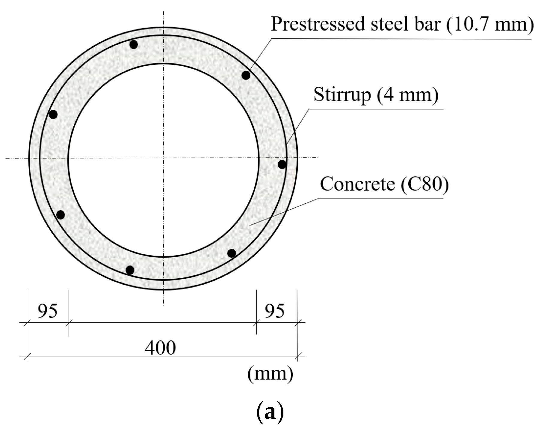
In this test, the PHC tube column specimen is a standard tube column with concrete grade of C80 (53.6 MPa in the characteristic compressive strength). The PHC tube column specimen is 5 m in column length, 400 mm in diameter, and 95 mm in wall thickness and equipped with seven prestressed main steel bars with the diameter of 10.7 mm. All prestressed steel bars are stretched to 0.7 times their standard tensile strength, that is the tension control ratio of the prestressed steel bars is 0.7. The PHC tube column specimen is made following the national building standards design atlas 10G409 Prestressed Concrete Pipe Piles, prepared by China Institute of Building Standard Design and Research [
31].
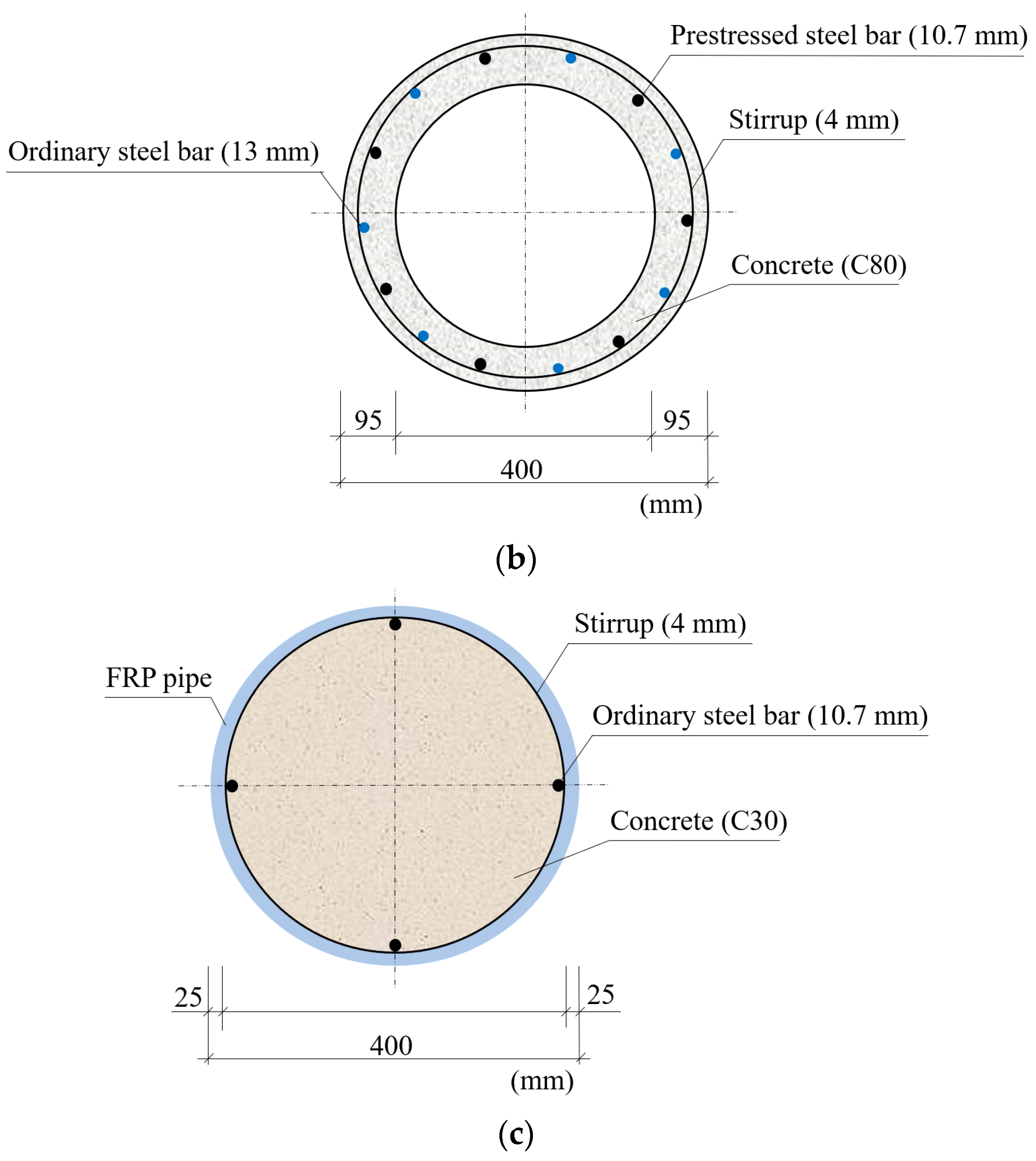
The parameter and configuration of the PRC tube column specimen are the same as those of the PHC tube pile specimen, except that there are seven other ordinary steel bars with the diameter of 12 mm.
The BFRPC composite column specimen is 5-m long, 400 mm in diameter, 25 mm in wall thickness of FRP tube, and C30 in concrete strength grade (22.6 MPa in the characteristic compressive strength). Four ordinary steel bars with a diameter of 16 mm are arranged along the whole length of the BFRPC composite column specimen, which is symmetrically fixed with stirrups and placed in FRP tube. The FRP tube in the BFRPC composite column specimen is made of the CBF material, and the basic parameters of the CBF material are shown in
Table 1.
The cross-sections of the three kinds of specimens are shown in
Figure 1. The basic parameters of the three types of column specimens are summarized in
Table 2.
2.2. Test Scheme
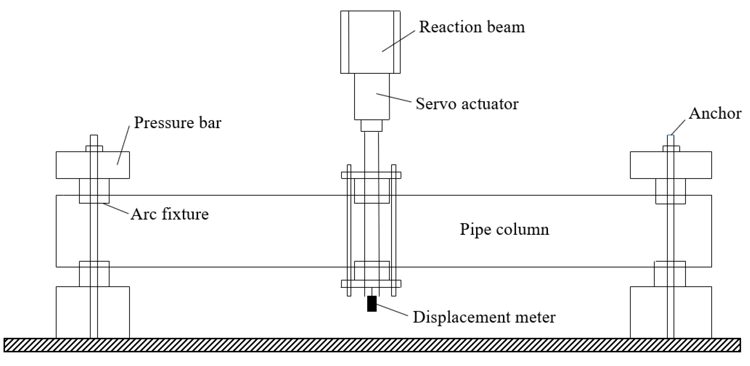
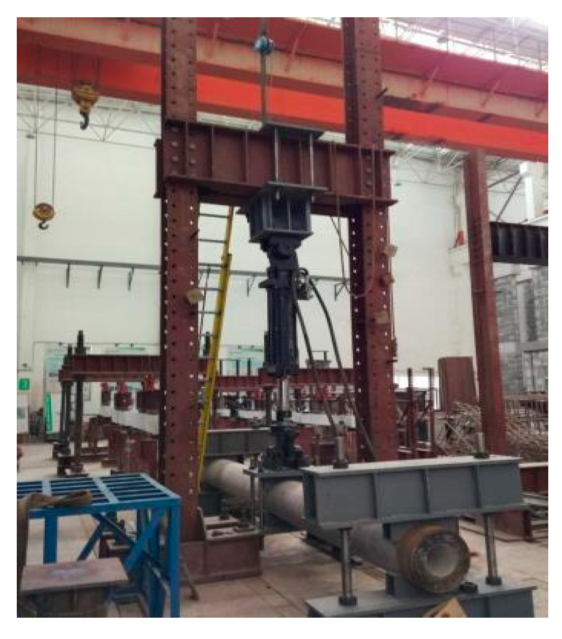
The test setup mainly includes vertical loading device (comprises the reaction beam and MTS electro-hydraulic servo loading system), displacement meter, pressure bar, arc fixture. Both ends of the column specimen are fixed boundaries. The schematic diagram of the loading device in this test is shown in
Figure 2. The assembled field loading device is presented in
Figure 3. At the same time, the electric measurement method is used to record the test data.
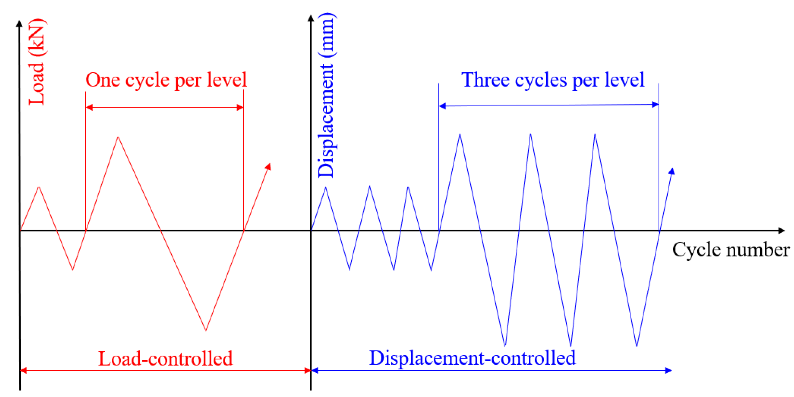
This test adopts the method of load-displacement dual control for the PHC and PRC tube column specimens. Differently, for the BFRPC composite column specimen, since no cracks appear during the test, the displacement-controlled method is directly employed for loading. The load-controlled method increases the load amplitude of each level by 10 kN during the first six levels of loading and by 5 kN thereafter, with one cycle per level and loading speed of 15 kN/min. The displacement-controlled method increases the displacement amplitude of each level by 10 mm during loading, with three cycles per level and loading speed of 5 mm/min. The number of cycles loading and the test termination condition are the same as those of PHC and PRC tube column specimens. The time–history control curve of the cyclic load is presented in
Figure 4.
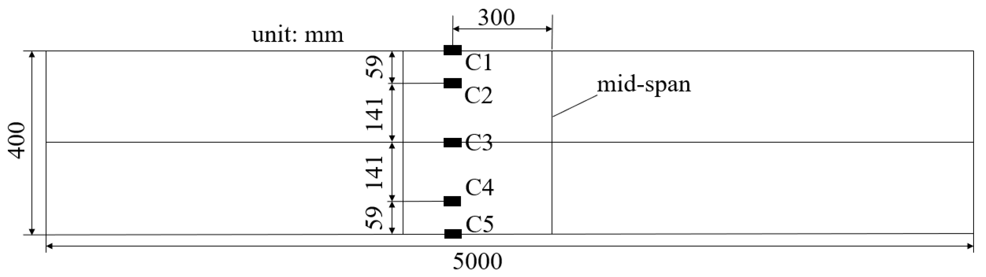
The concrete strain of the column body is measured by concrete strain gauges, and the data are collected by TST3827 data acquisition instrument. To avoid conflict with the position of the arc fixture, strain gauges are attached to the tension and compression sides at a distance of 30 cm from the mid-span of the column along the axis of the column body. The maximum tensile and compressive strain of the bending section for the column specimen can be measured from these two strain gauges. In addition, six strain gauges are arranged uniformly between these two strain gauges to measure the longitudinal strain at different section heights. The specific arrangement of strain gauges is displayed in
Figure 5.
The MTS electro-hydraulic servo loading system employed in this test can automatically collect the load and deflection values. However, since the arc fixture and the column body cannot be completely fitted, there is a certain gap between them. Therefore, when the load is small, the mid-span deflection of the column body is also slight. It results in a certain error between the displacement automatically collected by the MTS electro-hydraulic servo loading system and the actual displacement of the column body. For this reason, two displacement meters are arranged at the mid-span of the column specimen to monitor the actual mid-span displacement of the column body and correct the data collected from the electro-hydraulic servo actuator.
2.3. Test Results
2.3.1. PRC Tube Column Specimen
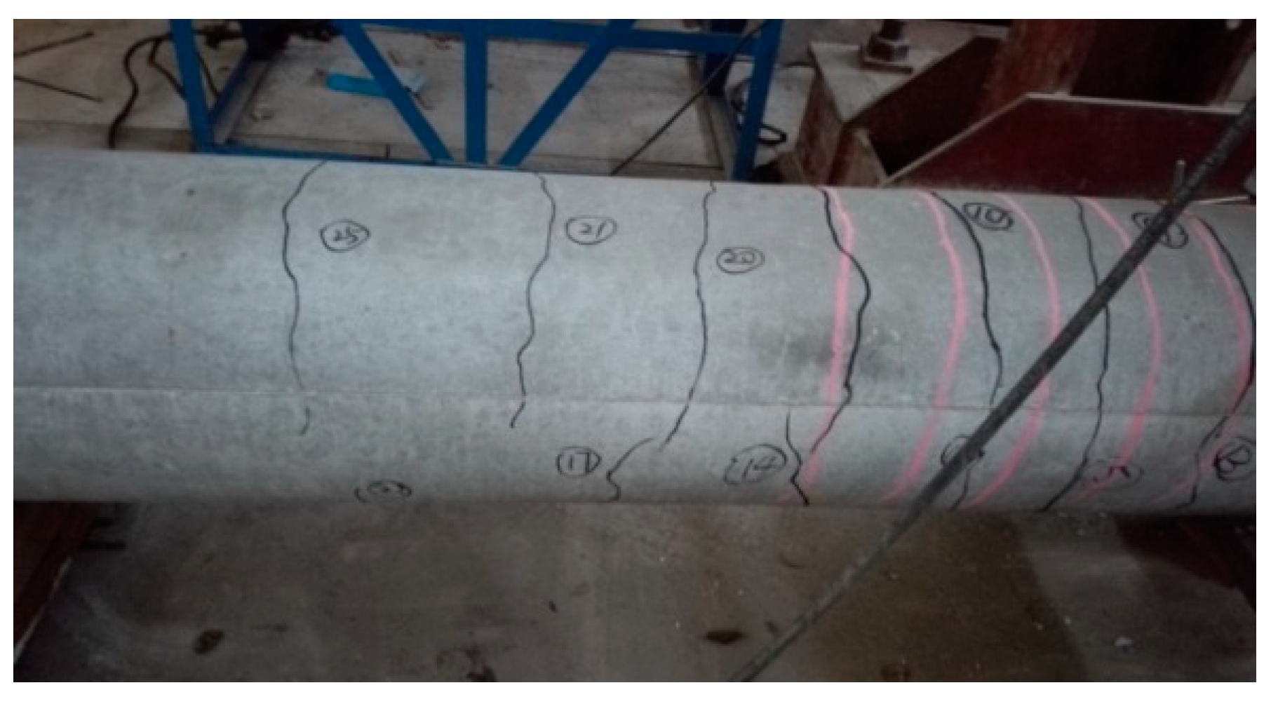
Some of the cracks generated in the column specimens during loading are presented in
Figure 6. When the forward loading (displacement downward) reached 60 kN, the mid-span displacement of the column specimen was 3.77 mm, and the first crack appeared near the mid-span of the lower part for the column body. When the reverse loading (displacement upward) of 60 kN was applied, the first crack could be completely closed, and no cracks appeared in the upper part of the column body. After that, the loading mode of the displacement-controlled method was adopted. The mid-span displacement of the column specimen formed by the first-level forward displacement loading was 12 mm, and that formed by the first-level reverse displacement loading was −10.68 mm. Under the first-level forward displacement loading, two cracks appeared on the left and right sides of the lower part for the column body, respectively. Under the first-level reverse displacement loading, three cracks appeared on one side of the upper part for the column body, and two cracks appeared on the other side. Moreover, the crack in the lower part of the column body caused by the first-level forward displacement loading extended to the upper part of the column body. After that, 2~3 new cracks were produced in the upper and lower parts of the column specimen under each level of forward and reverse displacement loading, respectively. Among them, the concrete in the mid-span of the column specimen was crushed under the fifth-level forward displacement loading, and the steel bars in the column specimen were fractured during the ninth-level forward displacement loading.
2.3.2. PHC Tube Column Specimen
The crack development of PHC tube column specimen is presented in
Figure 7. When the forward loading reached 75 kN, the mid-span displacement of the column specimen was 4.06 mm, and two cracks appeared near the mid-span of the lower part for the column body. When the reverse loading of 75 kN was applied, these two cracks could be completely closed, and no cracks appeared in the upper part of the column body. After that, the loading mode of the displacement-controlled method was adopted. The mid-span displacement of the column specimen formed by the first-level forward displacement loading was 9.23 mm, and that formed by the first-level reverse displacement loading was −7.52 mm. Under the first-level forward and reverse displacement loadings, one crack appeared on the left and right sides of both the lower and upper parts for the column body, respectively. Moreover, the crack in the lower part of the column body caused by the first-level forward displacement loading extended to the upper part of the column body during the first reverse displacement loading. After that, 1~2 new cracks were produced in the upper and lower parts of the column specimen under each level of forward and reverse displacement loading, respectively. During the third-level forward displacement loading, two steel bars inside the column specimen were fractured, and the other two steel bars were fractured during the third-level reverse displacement loading.
2.3.3. BFRPC Tube Column Specimen
The BFRPC composite column specimen was loaded directly by the displacement-controlled method. When the forward displacement was loaded to 10 mm, the corresponding load was 70.33 kN, and when the reverse displacement was loaded to 10 mm, the corresponding load was 65.22 kN. No cracks appeared on the surface of the FRP tube for the column specimen during the loading process. At continued displacement loading, the column specimen remained uncracked, but the deformation of the column specimen gradually increased. Moreover, the corresponding load increment decreased at each level of displacement increment; load to the late stage, the column body produced significant deformation. When the forward displacement was loaded to 140 mm, the corresponding load reached 554 kN, and the bearing capacity of the column specimen absented the decreasing trend. However, when the reverse displacement was loaded to 140 mm, the corresponding load reached 592 kN, the FRP tube in the mid-span of the column specimen was split, and the bearing capacity suddenly and significantly decreased. The test phenomenon of the BFRPC composite column specimen is shown in
Figure 8.
2.4. Test Phenomenon Comparison
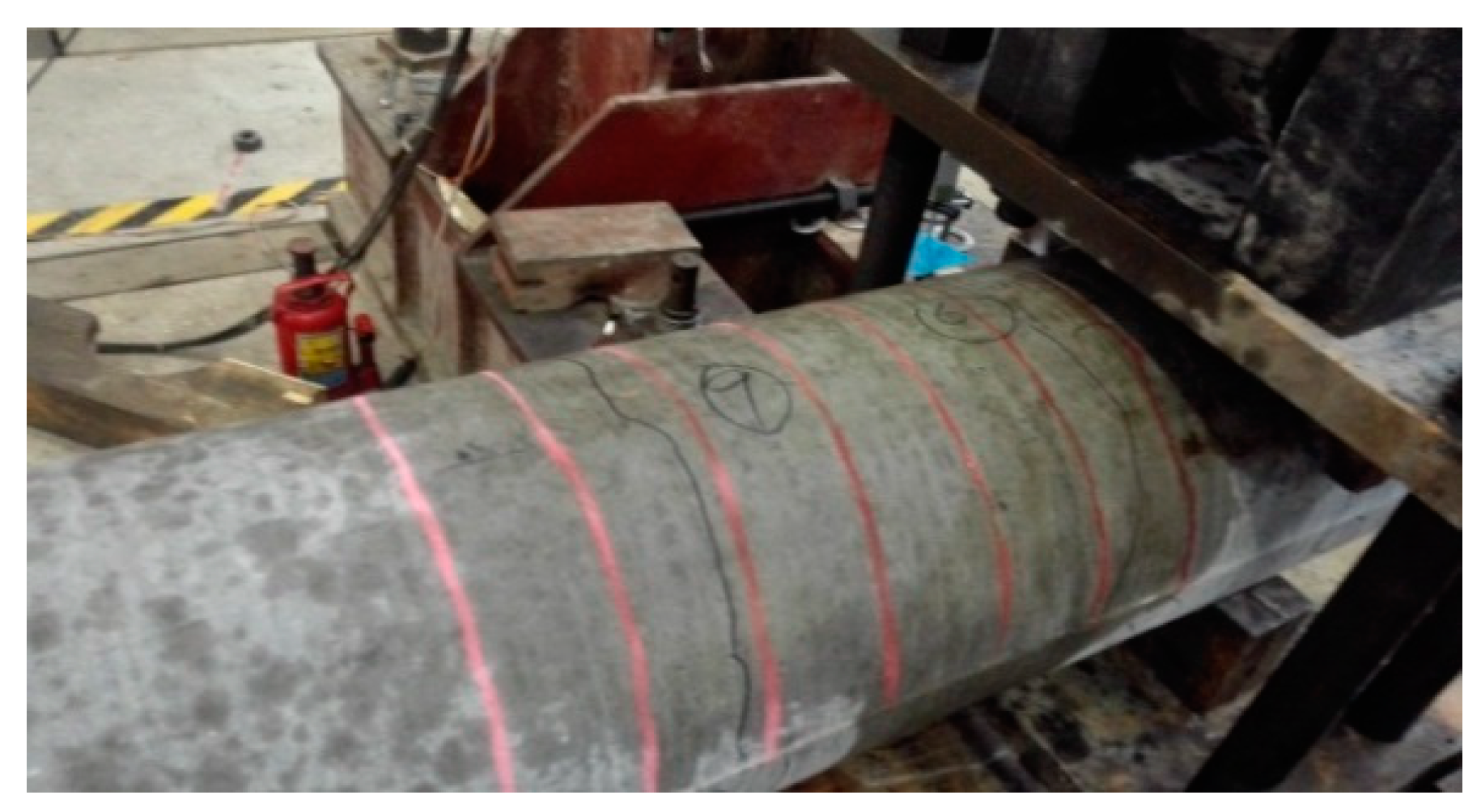
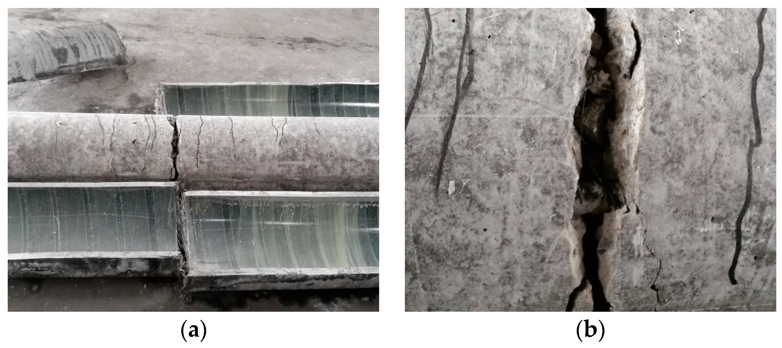
The first comparison is made in terms of the development of column cracks. The number and distribution of cracks on the concrete surface of the PRC tube column specimen are much larger than those of the PHC tube column specimen. The number of cracks appearing on the surface for the PRC tube column specimen was about 27, while about 12 for the PHC tube column specimen. The farthest crack appearing on the surface for the PRC tube column specimen was about 140 cm from the mid-span, while about 70 cm for the PHC tube column specimen. Differently, The BFRPC composite column specimen is difficult to observe the cracks of internal concrete directly due to the wrapping of continuous basalt fiber. The FRP tube needs to be dissected to observe the crack development in the internal concrete of the column specimen, as shown in
Figure 9. The BFRPC composite column specimen formed a crack with the width of 3 cm in the mid-span, and the steel bars were exposed. It indicates that the concrete has completely lost its bearing capacity in the later loading stage. The cracks produced in the BFRPC-combined column specimen show that the FRP tube with the wall thickness of 25 mm can withstand the load even when the steel bar and concrete completely lose their bearing capacity, indicating the excellent mechanical properties of the CBF material.
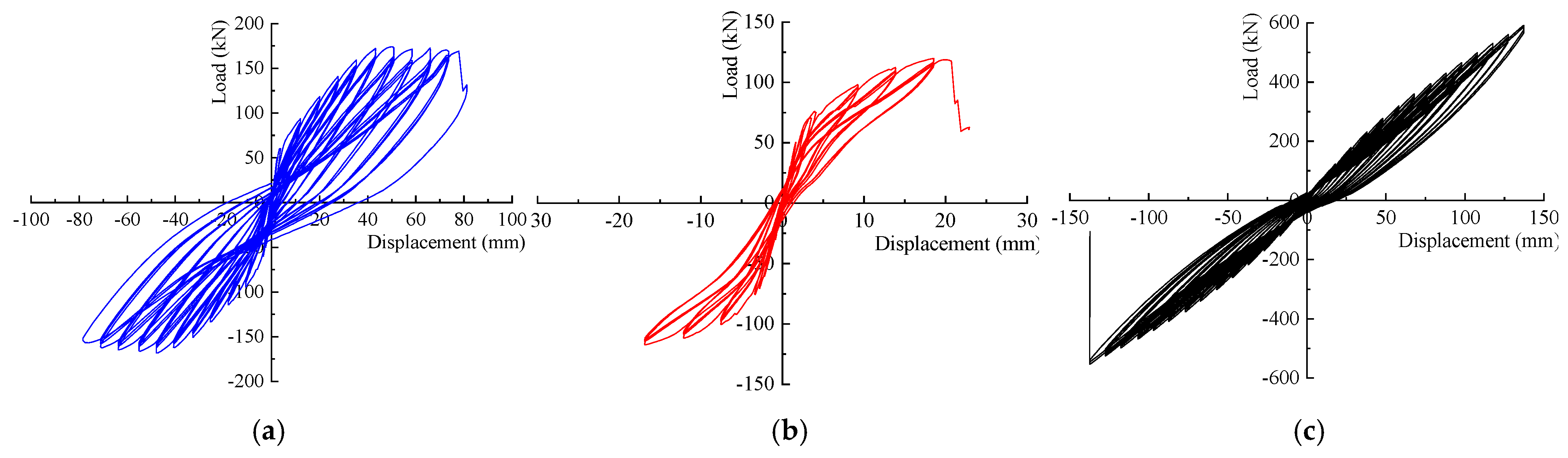
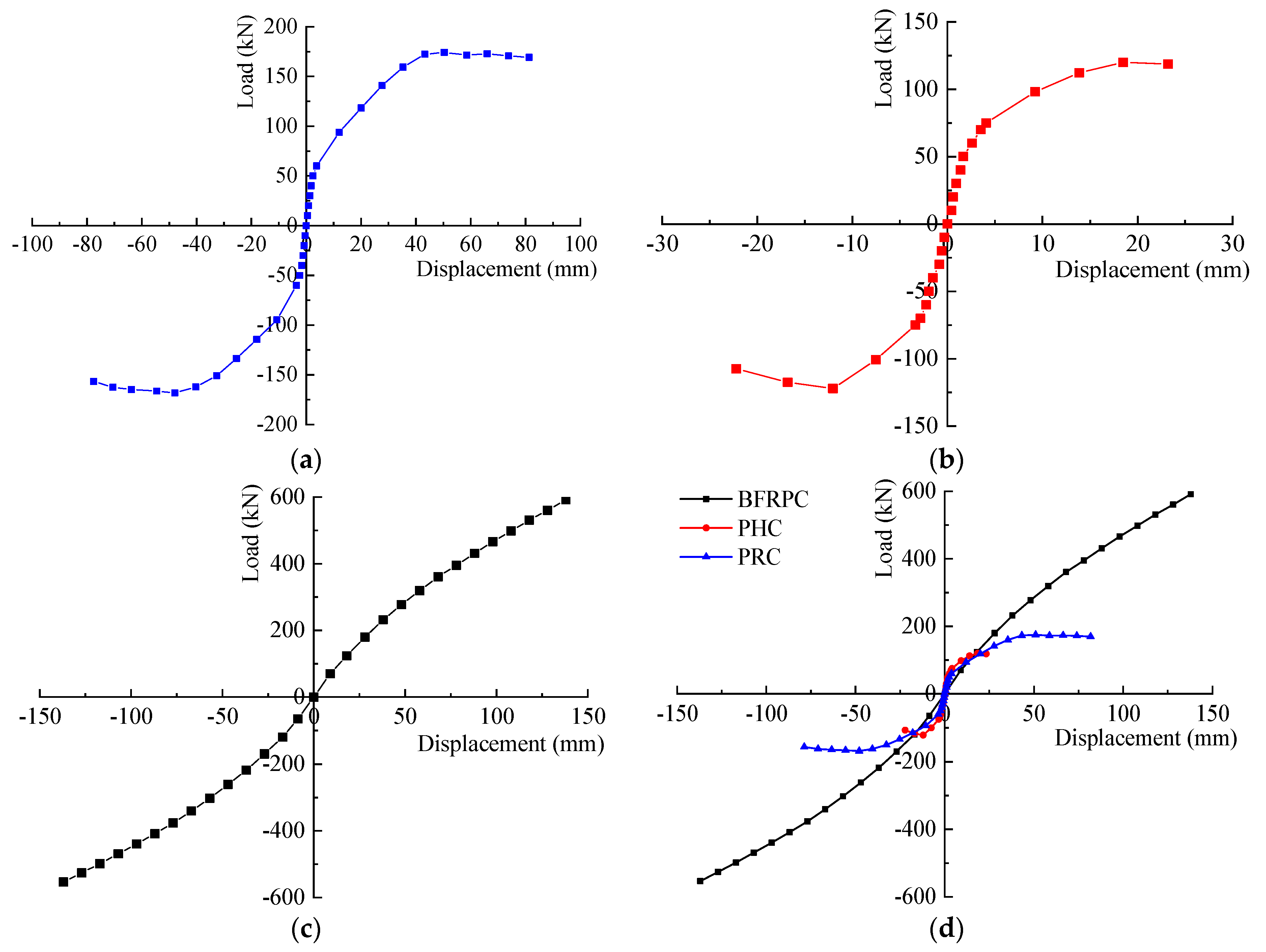
The second comparison is made in terms of the mid-span displacement. The mid-span displacements of PHC and PRC tube column specimens at failure are 23.21 mm and 81.76 mm, respectively, with the bearing capacity of 118.77 kN and 169.59 kN, respectively. The mid-span displacement of the BFRPC composite column specimen at failure is 140 mm, with the bearing capacity of 592.07 kN. It indicates that the configuration of ordinary steel bars can increase the ductility and ultimate bearing capacity of the column to a certain extent, and the employment of the FRP tube will increase that more significantly.
The third comparison is made in terms of the failure mechanism for column specimens. The bearing capacity of the PHC and PRC tube column specimens decreases suddenly due to the fracture of the steel bars. Differently, the bearing capacity of the BFRPC composite column specimen decreases due to the splitting of the FRP tube in the mid-span. In the initial loading stage, the external loads of all specimens are borne by their column concrete, while the internal steel bars are temporarily unstressed. With load increase, the prestressed steel bars in the PHC and PRC tube column specimens begin to bear the load, while the load of the BFRPC composite column specimen is dissipated by both the ordinary steel bars and FRP tube. With the further increase of load, the prestressed steel bars in the PHC tube column specimen reach the ultimate bearing capacity and break, resulting in the destruction of the column specimen. At this time, the ordinary steel bars in the PRC tube column specimen begin to bear the load together with the prestressed steel bars, and the FRP tube in the BFRPC composite column specimen begins to play a major role in bearing the load. At the end of loading, the steel bars in the PRC tube column specimen break, resulting in the specimen to break and lose its bearing capacity. Although the steel bars in the FPRC composite column specimen yield and the concrete crack, the FRP tube can still bear most of the loads until the mid-span CBF material reaches the ultimate bearing capacity and splits, thus causing the specimen to fail.
4. Conclusions
In this work, the load-carrying capacity, deformation characteristic, and ductility performance of the BFRPC composite column under cyclic lateral loading were investigated through comparing with PHC and PRC tube columns. The failure features, hysteretic curve, and skeleton curve for the three columns were compared and analyzed through the load–displacement hysteretic curve. The main conclusions are as follows:
- (1)
The forward/reverse extreme loads are 118.77 kN/107.44 kN for the PHC tube column specimen, 169.59 kN/156.93 kN for the PRC tube column specimen, and 592.07 kN/553.72 kN for the BFRPC composite column specimen. The forward/reverse extreme displacements are 23.21 mm/22.21 mm for the PHC tube column specimen, 81.76 mm/78.74 mm for the PRC tube column specimen, and 140 mm/140 mm for the BFRPC composite column specimen.
- (2)
The BFRPC composite column is about 5 times and 6 times than PHC tube column and is about 3.5 times and 2 times than PRC tube column for the horizontal bearing capacity and extreme displacement, respectively.
- (3)
The failure of the BFRPC composite column belongs to ductile failure without yield point, and its ductility is significantly less than that of PRC tube column. The PHC tube column presents a certain brittle failure behavior.
- (4)
For the BFRPC composite column the installation of FRP tube is equivalent to an increase in the reinforcement ratio of the concrete column, which can significantly improve its ultimate load carrying capacity.
- (5)
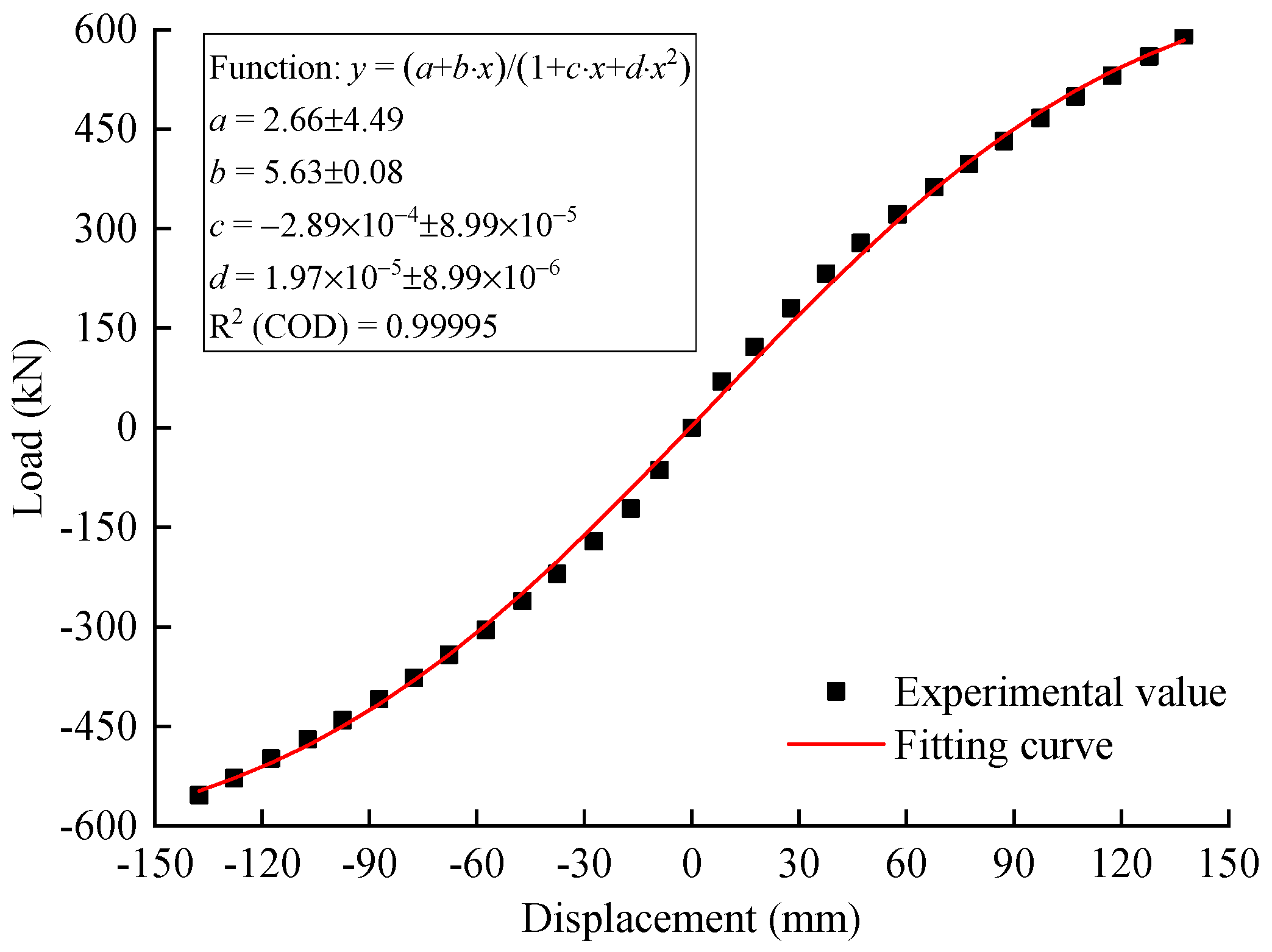
The functional form for the skeleton curve of BFRPC composite column can be approximately represented by the inverse hyperbolic sine function.
The above results are expected to provide a technical support and mathematical basis for the horizontal bearing design of BFRPC composite columns.


