Article

Accurate Inner Profile Measurement of a High Aspect Ratio Aspheric Workpiece Using a Two-Probe Measuring System

The State Key Laboratory of Fluid Power and Mechatronic Systems, Zhejiang University, Hangzhou 310027, China
*
Author to whom correspondence should be addressed.
Appl. Sci. 2022, 12(13), 6628; https://doi.org/10.3390/app12136628
Submission received: 14 April 2022 / Revised: 19 June 2022 / Accepted: 28 June 2022 / Published: 30 June 2022
(This article belongs to the Special Issue Precision Manufacturing and Intelligent Machine Tools)

Abstract

:
This paper presents a novel method for inner profile measurement and geometric parameter evaluation, such as the radius of the bottom, steepness and straightness of the steep sidewall of a high aspect ratio aspheric workpiece, by utilizing a two-probe measuring system, which includes a lateral displacement gauge for the inner steep sidewall profile measurement and an axial displacement gauge for the inner deep underside profile measurement. To qualify the measurement accuracy, the systematic errors associated with the measurement procedure, including the miscalibration, misalignment and the roundness error of the gauge probes, as well as the slide motion error of the four-axis motion platform, are all evaluated and separated from the measurement results. A point cloud registration algorithm is employed to stitch the evaluated inner sidewall profile and the inner underside profile to form an entire inner profile of the workpiece. To verify the performance of the newly proposed method, the inner profile of a high aspect ratio aspheric workpiece, which has a tapered cone shape with a maximum inner radius of 40 mm, a maximum inner depth of 140 mm and a steep sidewall angle approaching 85°, is measured in experiments. The measurement result is compared with that of a coordinate measuring machine (CMM), and the comparison verifies the feasibility of the proposed measurement system.

1. Introduction

High aspect ratio aspheric workpieces are widely used in precision systems in aerospace, nuclear physics and other fields, such as rocket engines and spaceships [1,2]. The dimensional accuracy of the high aspect ratio aspheric workpiece is important since the geometric errors would greatly influence the performance reliability of the systems [3,4]. For example, in the rocket engine nozzles, the surface error and geometric error above the micrometer level will affect the stable flow state of the tail flame, resulting in the degradation of the engine performance [5]. A high aspect ratio aspheric workpiece is mainly produced by grinding or lapping processes [6,7]. Due to its high aspect ratio profile, it is normally a challenge to obtain high accuracy only with the manufacturing process without measurement since the control of multi-motion axes of the machine tool to track a high aspect ratio and large amplitude profile is always suffering from low accuracy compared with that of a smooth profile [8]. Therefore, to ensure the geometric accuracy of the workpiece, it is necessary to accurately evaluate the geometric shape of the high aspect ratio aspheric workpiece [9], especially its inner profile, which is normally difficult to measure, while the outer surface profile can be relatively easily probed by many existing methods.
Many efforts have been carried out to evaluate the geometric profile of aspheric workpieces. Some studies based on the coordinate measuring machine (CMM) have been utilized for dimensional measurement [10,11,12,13]. Although CMM with a long tactile probe or state-of-art technique can perform a profile measurement of the high aspect ratio aspheric surfaces [14,15,16,17], it is a cost of capital to prepare such an instrument for the routine inspection of the high aspect ratio aspheric part. In addition, it is burdensome to reform a CMM for on-machine measurement for high aspect ratio aspheric surfaces with different geometry characteristics. The ultrasonic method is commonly used for thickness measurement [18,19]. Nevertheless, the ultrasonic method cannot measure the inner profile directly and accurately since its measurement resolution is generally on the order of just a few tens of micrometers, which is not suitable for precision measurement, which requires micrometer uncertainty. Laser triangulation sensors and the fringe projection profilometry method are also applied to evaluate the geometric form of the aspheric workpieces [20,21]. It is also noted that the V-block method can be applied to evaluate the roundness and waviness profiles of the cylindrical parts in industrial conditions [22]. These methods are effective for the outer profile measurement but cannot measure the entire inner profile of the high aspect ratio aspheric workpiece because the detectable angle of the optical measuring methods is limited [23].
Motivated by the limitation of capability and efficiency to measure the high aspect ratio aspheric workpiece, a measurement method of utilizing two displacement gauges on a four-axis motion platform to evaluate the entire inner profile of a high aspect ratio aspheric workpiece with a steep sidewall is proposed. Differing from traditional methods that can only measure the upper or the bottom part of the inner profile of the high aspect ratio workpiece, this paper proposed a novel method for measuring the whole inner profile and evaluating the geometric parameters, such as the radius of the bottom spherical shape and the steepness and straightness of the sidewall, with a two-probe measurement setup. The characteristic of the proposed measurement method also enables the ability to evaluate the waviness profile and roundness of the inner and outer surfaces. The key advantage of this method is that the measurement can be performed without significant investment in time and capital to assess the profile of the high aspect ratio workpiece accurately with high compatibility for on-machine measurement.
In this paper, after introducing the measurement system and principle, to qualify the measurement accuracy, the systematic errors associated with the measurement procedure, including the miscalibration, misalignment and the roundness error of the gauge probes, as well as the slide motion error of the four-axis motion platform, are all evaluated and separated from the measurement results. A high aspect ratio aspheric workpiece, which has a tapered cone shape with a maximum inner radius of 40 mm and a maximum inner depth of 140 mm, is evaluated in experiments based on the proposed method. The experimental result is compared with that of a coordinate measuring machine (CMM), and the comparison result proves the feasibility of the proposed measurement system.

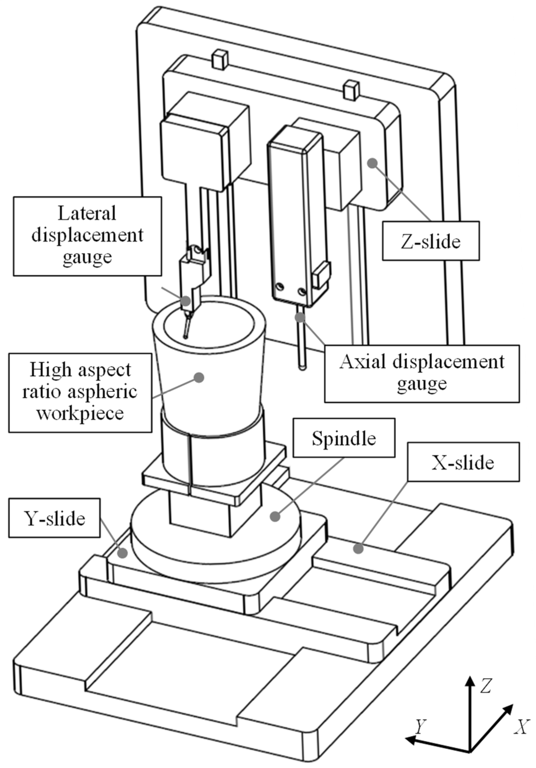
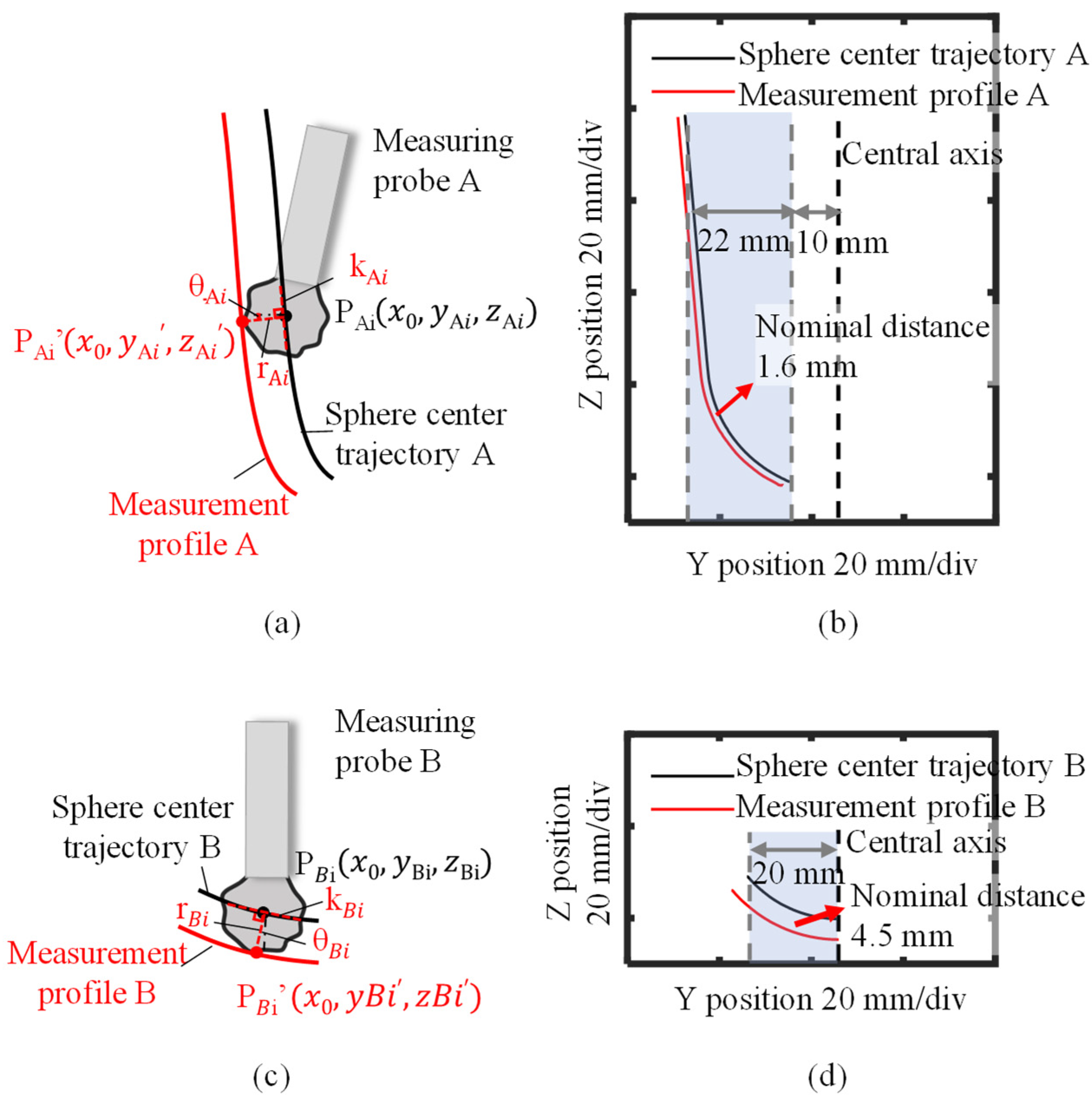
2. Measurement System and Basic Measurement Principle

As shown in Figure 1, the measurement system is established based on a four-axis motion platform with XYZ slides and a spindle. A schematic of the error of the inner profile of the high aspect ratio aspheric workpiece is shown in Figure 2. The right side of the single cross-section can be measured by rotating the spindle and the workpiece by 180° after measuring the left side of the single cross-section with a precision rotation stage. The workpiece has a tapered cone shape with a steep sidewall and a depth much larger than its opening diameter. The measurement target is its entire inner profile, including the steep side part and the shallow bottom part at a deep depth. The high aspect ratio aspheric workpiece is mounted on the spindle, which can be driven by the XY-slide. A lateral displacement gauge (Probe A) for measuring the inner sidewall profile and an axial displacement gauge (Probe B) for measuring the inner underside profile of the high aspect ratio aspheric workpiece are both mounted on the Z-slide of the motion platform. The side part of the inner profile can be measured by Probe A while driving the Z-slide and the Y-slide to keep the probe within its measurement range. The inner underside profile can be measured by Probe B while only driving the Y-slide.
Figure 3 shows the measurement procedure for evaluating the entire inner profile of the high aspect ratio aspheric workpiece. The inner sidewall profile measurement and the inner underside profile measurement are measured by Probe A and Probe B, respectively, and then the measurement results are stitched together by applying a point cloud registration algorithm [24].
Firstly, the inner sidewall profile of the high aspect ratio aspheric workpiece is measured using Probe A. During the measurement procedure, Probe A is employed to scan by starting from the top edge of the high aspect ratio aspheric workpiece and ending at the limited position of its measuring range, which has a horizontal distance dA from the central axis of the high aspect ratio aspheric workpiece. The trajectory of the center of the probing sphere of Probe A can be obtained by:
y b a l l _ A = y s l i d e + Δ y b a l l _ A
z b a l l _ A = z s l i d e + Δ z b a l l _ A
where yball_A and zball_A are the Y coordinate and the Z coordinate of the center of the probing sphere of Probe A, respectively, yslide and zslide are the Y-slide position and Z-slide position obtained from the four-axis motion platform, ∆yball_A is the Y-axis displacement of the probing sphere obtained as the output of Probe A, and ∆zball_A is the undesired Z-axis displacement of the probing sphere of Probe A associated with its Y-axis displacement, which shall be calibrated. This calibration of the undesired Z-axis displacement is explained later. Since the inner sidewall profile of the workpiece has a normal distance, which is the radius rA of the probing sphere of Probe A, from the trajectory of the measuring Probe A, the inner sidewall profile of the workpiece can be evaluated based on the trajectory and the information of the probing sphere radius.
Then, the inner underside profile of the workpiece is measured using Probe B. During the measurement procedure, Probe B is employed to scan starting from the central axis of the workpiece and ending at its limited measuring range position, having a horizontal distance from the central axis of the high aspect ratio aspheric workpiece of dB. The trajectory of the probing sphere of Probe B can be obtained by:
y b a l l _ B = y s l i d e
z b a l l _ B = z s l i d e + Δ z b a l l _ B
where yball_B and zball_B are the Y coordinate and Z coordinate of the probing sphere of Probe B, yslide and zslide are the Y-slide position and Z-slide position obtained from the four-axis motion platform, and ∆zball_B is the Z-displacement of the probing sphere obtained as the output of Probe B. It should be noted that the probing sphere of the axial gauge can only move in the Z-direction, and the displacement in the Y-direction caused by the elastic deformations is neglected. The relative displacement in the Y-direction is not involved in Equation (3). Similar to the measurement of the sidewall profile, the inner underside profile of the workpiece can be evaluated based on the scan trajectory of the probe and the information on the probing sphere radius. Finally, a point cloud registration algorithm is implemented to stitch the inner sidewall profile measured by the lateral displacement gauge and the inner underside profile measured by the axial displacement gauge.
The proposed measurement method makes it possible to evaluate the entire inner profile of the high aspect ratio aspheric workpiece with two displacement gauges on a four-axis motion platform. However, the measurement results contain various errors, including the miscalibration, misalignment and roundness error of the probing sphere of the two probe gauges, as well as the slide motion error of the four-axis motion platform, as shown in Figure 4. To obtain an accurate measurement result, attention should be paid to evaluating, separating and compensating for the errors in the measurement system.

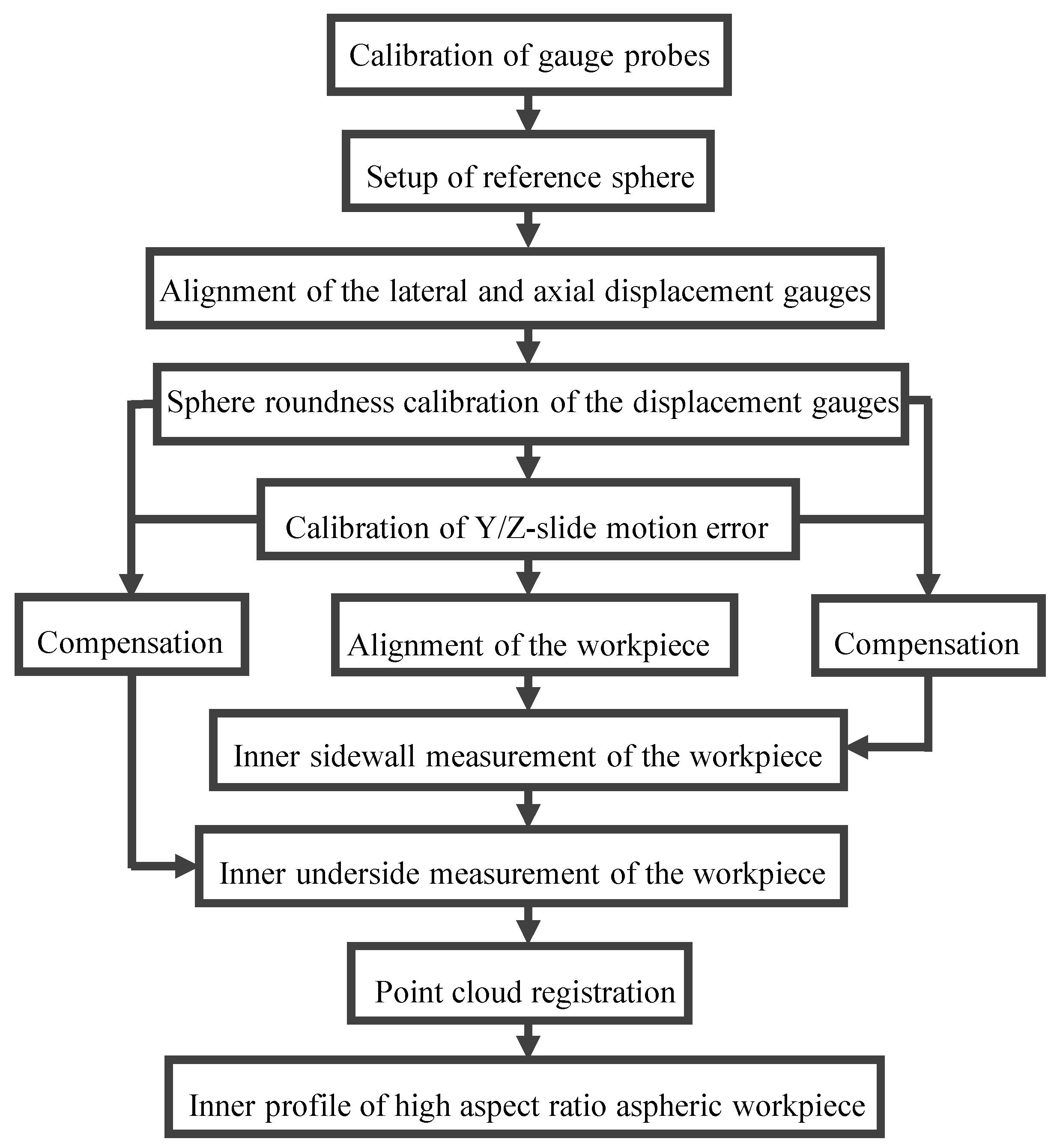
3. Calibration of the Measurement System

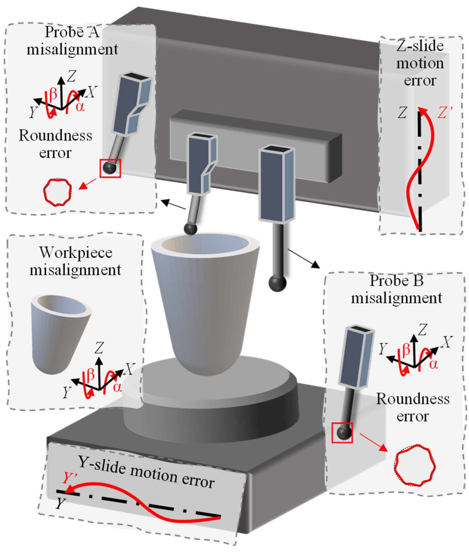
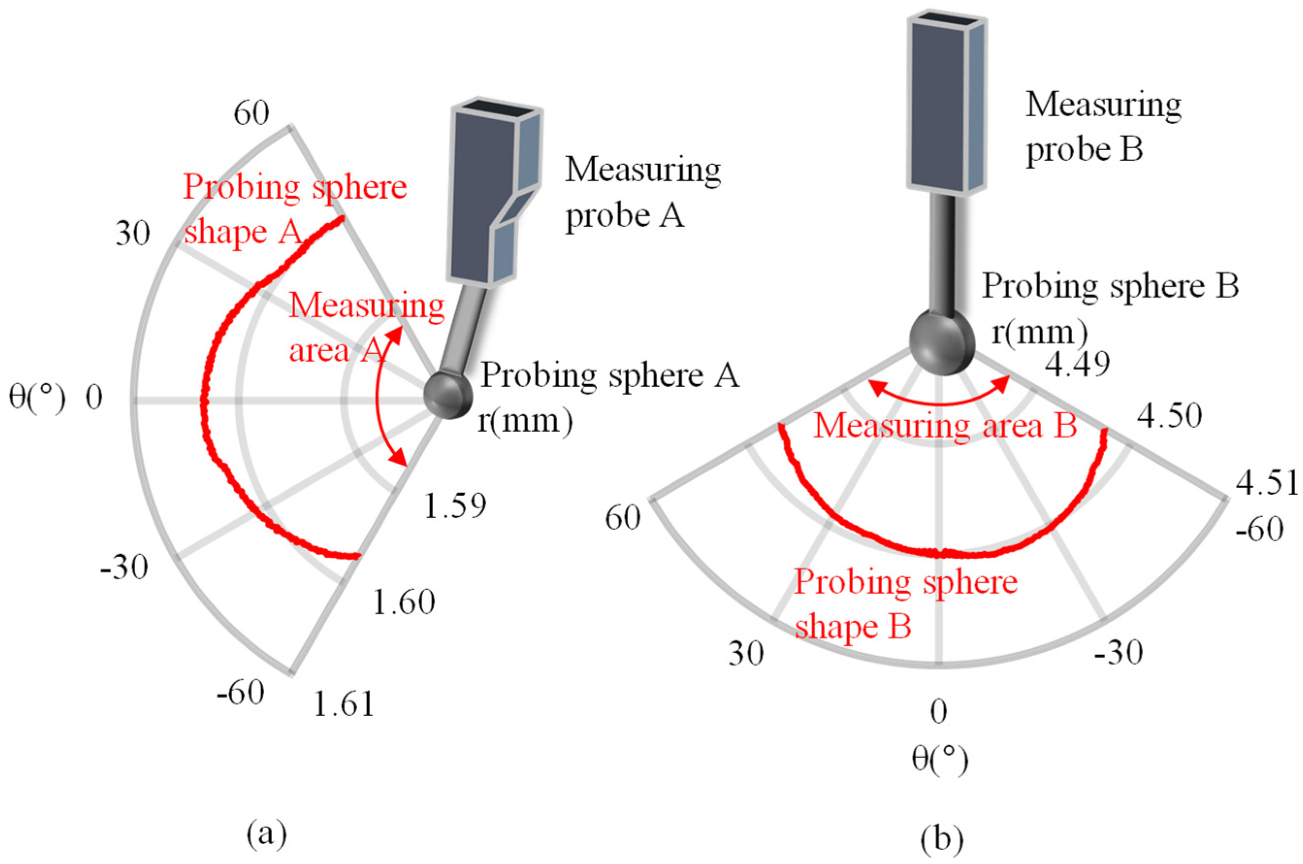
3.1. Calibration of the Measuring Probes

To implement the measurement of the inner profile of the high aspect ratio aspheric workpiece, the lateral displacement gauge and the axial displacement gauge must have high measurement accuracy and good linearity of tens of nanometers, especially for the lateral displacement gauge due to the nonlinearity of its inner structure and its output circuit. The calibration procedure for the lateral displacement gauge is shown in Figure 5.
The lateral displacement gauge is mounted on the Z-slide and a standard gauge block is mounted on the Y-slide for calibration. To calibrate the horizontal measurement of the lateral displacement gauge, as shown in Figure 5a, the measurement output of the lateral displacement gauge varies from Si to Si+1 while the Y-slide moves from Yi to Yi+1, and the measurement error of the lateral displacement gauge can be evaluated as:
e i = ( S i + 1 S i ) ( Y i + 1 Y i )
Taking a series of samples within the measurement range of the lateral displacement gauge, the measurement error of each measurement output can be evaluated. It should be noted that the resolution of the Y-slide is 20 nm, and the repetition error of the Y-slide is ±5 nm. The errors of ±25 nm of the Y-slide are much smaller than the errors of the lateral gauge, which is ±293 nm before calibration, according to results shown in Section 4.2.
Furthermore, the calibration procedure should be carried out several times to achieve a stable calibration accuracy to reduce the effect of the errors of the Y-slide. In addition, the structure of the lateral gauge looks similar to a simple pendulum. During the measurement, there are crosstalk displacements of the probing sphere in the Y-direction and Z-direction with respect to the gauge body. The displacement in Y-direction is measured by the lateral gauge, while the displacement in the Z-direction is ignored. Thus, the crosstalk displacement in the Z-direction should be calibrated. As shown in Figure 5b, the crosstalk output of the lateral displacement gauge with respect to the movement along the Z-slide is calibrated by linking the gauge probe with the Y-slide by a spring. The little spring pushes the probe of the lateral gauge to the right side and keeps the probe in contact with the standard gauge block. When the Z-slide moves down from Zj to Zj+1, the output correspondingly varies from Sj to Sj+1. Thus, the relationship between the lateral gauge output and its vertical movement can be obtained for compensation:
Δ Z j = Z j + 1 Z j S j + 1 S j Δ S j
Moreover, the lateral displacement gauge and the axial displacement gauge should be carefully mounted vertically to reduce the cosine error [25]. To evaluate the misalignment error of the two displacement gauges, a reference sphere with a radius of R is used, as shown in Figure 6. Tilt alignment of the lateral displacement gauge with a roll angle in the YZ-plane of αA is shown in Figure 6a. Firstly, the lateral probe is moved along the X-axis to find the minimum measurement output position and the YZ-plane of this position is the YZ central cross-section plane of the reference sphere.
The lateral displacement gauge, which is moved along the Z direction, is employed to measure the reference sphere from the position ZA0, which has the minimum output of SA0 to the position ZAn, with the output of SAn reaching the limited value of the measurement range. According to Figure 6a, in the right triangle of OAnTAPA, we have the following geometric relationships:
O A n P A = S A n S A 0
O A n T A = O A n P A · cos α A = ( S A n S A 0 ) · cos α A
P A T A = O A n P A · sin α A = ( S A n S A 0 ) · sin α A
In the right triangle of OAQAOAn, we have the following geometric relationships:
O A O A n = R + r A
O A Q A = O A O A 0 Q A O A 0 = O A O A 0 O A n T A = R + r A ( S A n S A 0 ) · cos α A
Q A O A n = T A O A 0 = P A O A 0 P A T A = Z A n Z A 0 ( S A n S A 0 ) · sin α A
| O A O A n | 2 = | O A Q A | 2 + | Q A O A n | 2
2 ( S A n S A 0 ) × ( ( R + r A ) · cos α A + ( Z A n Z A 0 ) · sin α A ) = ( Z A n Z A 0 ) 2 + ( S A n S A 0 ) 2
Then, according to Equation (14), the roll angle αA of the lateral displacement gauge in the YZ-plane can be evaluated. Similarly, the tilt alignment of the axial displacement gauge with a roll angle in the YZ-plane of αB is carried out as shown in Figure 6b, and we can formulate a similar right triangle of OBQBOBn, which follows the relationships:
O B O B n = R + r B
O B Q B = O B O B 0 Q B O B 0 = O B O B 0 O B n T B = R + r B ( S B n S B 0 ) · cos α B
Q B O B n = T B O B 0 = P B O B 0 P B T B = Y B n Y B 0 ( S B n S B 0 ) · sin α B
| O B O B n | 2 = | O B Q B | 2 + | Q B O B n | 2
2 ( S B n S B 0 ) × ( ( R + r B ) · cos α B + ( Y B n Y B 0 ) · sin α B ) = ( Y B n Y B 0 ) 2 + ( S B n S B 0 ) 2
According to Equation (19), the roll angle αB of the axial displacement gauge in the YZ-plane can be evaluated. Similarly, the pitch angle of the measuring probe can be evaluated by changing the scanning direction to the X-axis. The roll and pitch angles can thus be corrected by adjusting the corresponding manual tilt stage, which is mounted behind the probe fixture.
In addition, since the inner profile is the envelope of the trajectory of the center of the probing sphere, the inner profile can be calculated based on the trajectory of the center of the probing sphere and the sphere radius. The probing sphere roundness error of the two gauges would affect the calculation accuracy and reduce the accuracy of the measurement profile. It is necessary to evaluate and compensate for the roundness error of the probing sphere of the gauge probes. The aligned measuring probes are shown in Figure 7, where the lateral gauge measurement is mounted vertically to measure the exact horizontal displacement, and the axial gauge is mounted vertically to measure the exact vertical displacement. To evaluate the probing sphere roundness of the lateral gauge, the lateral gauge is moved along the Z direction, as shown in Figure 7a, which is similar to that of Figure 6a. ZA0 is the start position of the lateral gauge, and ZAi is an intermediate calibration position. At the position of ZAi, in the right triangle of OAQAiOAi, we have the following geometric relationships:
O A O A i = R + r A i
O A Q A i = O A O A 0 Q A i O A 0 = O A O A 0 ( S A i S A 0 ) = R + r A 0 S A i + S A 0
Q A i O A i = Z A i Z A 0
| O A O A i | 2 = | O A Q A i | 2 + | Q A i O A i | 2
r A i 2 + 2 R · r A i = r A 0 2 + ( S A i S A 0 ) 2 + ( Z A i Z A 0 ) 2 + 2 R · r A 0 2 ( R + r A 0 ) · ( S A i S A 0 )
θ A i = arcsin Q A i O A i O A O A i = arcsin Z A i Z A 0 R + r A i
According to Equations (24) and (25), the exact radius rA0 could be measured by a coordinate measurement machine, and the radius rAi of the probing sphere of the lateral gauge at an angular range θAi of −60° ≤ θAi ≤ −60° due to the limitation of its measuring range can be evaluated. Similarly, to evaluate the probing sphere roundness error of the axial gauge, as shown in Figure 7b, in the right triangle of OBQBiOBi, we have the following geometric relationships:
O B O B i = R + r B i
O B Q B i = O B O B 0 Q B i O B 0 = O B O B 0 ( S B i S B 0 ) = R + r B 0 S B i + S B 0
Q B i O B i = Y B i Y B 0
| O B O B i | 2 = | O B Q B i | 2 + | Q B i O B i | 2
r B i 2 + 2 R · r B i = r B 0 2 + ( S B i S B 0 ) 2 + ( Y B i Y B 0 ) 2 + 2 R · r B 0 2 ( R + r B 0 ) · ( S B i S B 0 )
θ B i = arcsin Q B i O B i O B O B i = arcsin Y B i Y B 0 R + r B i
According to Equations (30) and (31), the exact radius rB0 could be measured by a coordinate measurement machine, and the radius rBi of the probing sphere of the axial gauge at an angular range θBi of −60° ≤ θBi ≤ −60° can be evaluated. The evaluated sphere roundness error of the lateral gauge and the axial gauge can then be compensated in the evaluation of the inner profile of the workpiece based on the trajectory of the measuring sphere of the gauges.

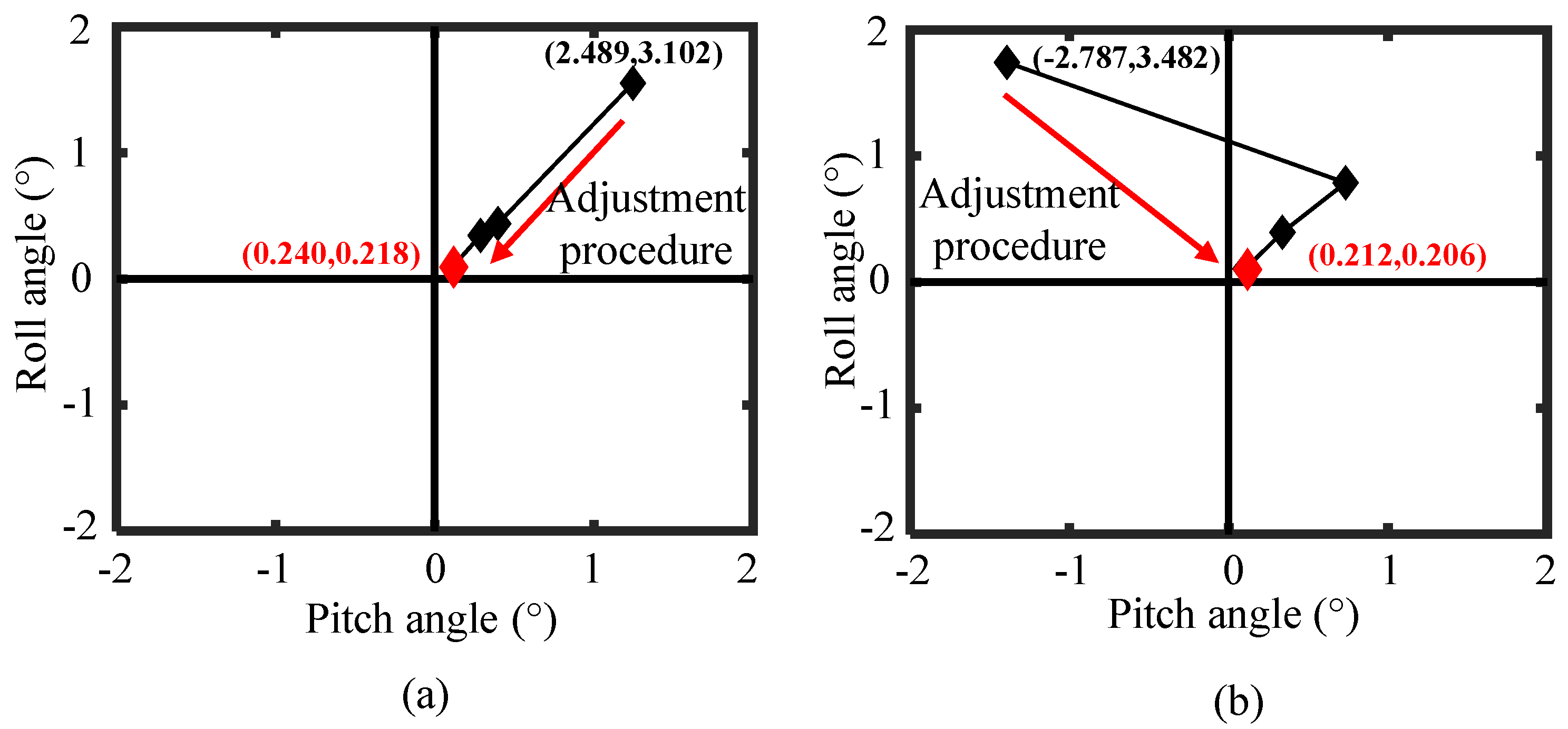
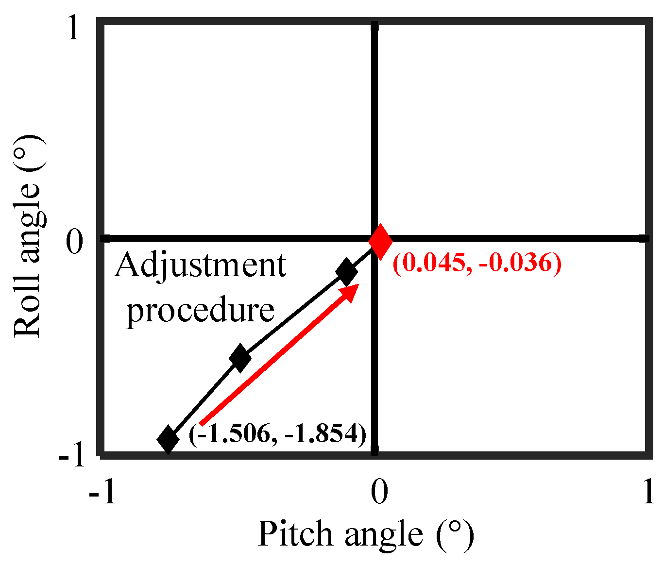
3.2. Alignment of the High Aspect Ratio Aspheric Workpiece

For the alignment of the high aspect ratio aspheric workpiece, there are tilt misalignment errors with a roll angle θβ about the X-axis and a pitch angle θα about the Y-axis. The lateral gauge mounted on the Z-slide is applied to measure the sidewall of the inner profile to calibrate the misalignment error of the workpiece, as shown in Figure 8. The basic concept is to identify the point with the largest distance from the central point of the workpiece at two different heights of z1 and z2, respectively. As shown in Figure 8a, the lateral gauge is moved from X0 along the negative X-axis to identify the largest distance point from the central point of the workpiece when the output of the lateral gauge reaches the maximum. To evaluate the pitch angle θα of the workpiece, the first step is to mark the point P1′(x1′, y1′, z1′) with the largest distance from the central point of the workpiece at the height of z1′ while moving the lateral gauge along X-axis. Then the point P2′(x2′, y2′, z2′) with the largest distance from the central point of the workpiece at the height of z2′ can also be identified based on a similar procedure. According to the geometric relationship shown in Figure 8b, the pitch angle θα of the high aspect ratio aspheric workpiece can be evaluated through the following equation:
θ α = arctan x 1 x 2 z 2 z 1
In the same way, the roll angle θβ of the high aspect ratio aspheric workpiece can be obtained by:
θ β = arctan y 3 y 4 z 4 z 3
where P3′(x3′, y3′, z3′) is the largest distance point from the center of the workpiece at the height of z3′, and P4′(x4′, y4′, z4′) is the largest distance point from the center of the workpiece at the height of z4′ while moving the lateral gauge along the Y-axis. The pitch and roll angle can thus be corrected by adjusting the corresponding manual tilt stage, which is mounted under the high aspect ratio aspheric workpiece fixture. It should be noted that the alignment should be carried out several times at different heights to reduce the effect of the roundness errors of the workpiece to achieve a stable alignment accuracy.

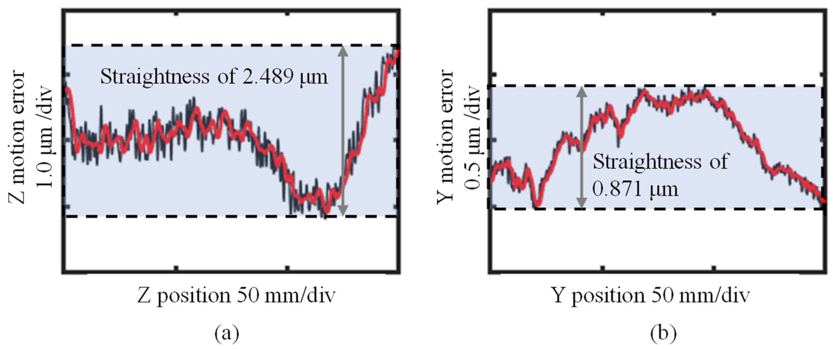
3.3. Identification of the Slide Error Motion

During the measurement procedure, the Z-slide of the motion platform is used to drive the measuring gauge to move along the Z-axis, while the Y-slide of the motion platform is used to drive the high aspect ratio aspheric workpiece to move along the Y-axis to keep the measuring gauge in contact with the inner profile of the workpiece. Thus, the motion errors of the Z-slide and the Y-slide would influence the measurement accuracy [13]. To ensure measurement accuracy, it is necessary to evaluate and compensate for the motion errors of the Z-slide and the Y-slide.
The identification procedure of the slide motion errors is expressed in Figure 9. For evaluating the motion error of the Z-slide, as expressed in Figure 9a,b, the lateral gauge mounted on the Z-slide and a standard gauge block mounted on the Y-slide are applied. Firstly, the lateral gauge is moved to perform a circular motion on the right side of the standard gauge block and the peak-to-valley output of the lateral gauge is evaluated. The tilt stage mounted under the standard gauge block is then adjusted to keep the peak-to-valley output within 100 nm to make sure that the right side of the standard gauge block is parallel to the XZ-plane of the motion platform. After that, the lateral gauge is moved along the Z-axis to measure the right side of the standard gauge block. During this measurement procedure, only the Z-slide moves and the variation of the lateral gauge output represents the motion error of the Z-slide of the motion platform. Similarly, by applying the axial gauge mounted on the Z-slide and the standard gauge block mounted on the Y-slide, the axial gauge is controlled to perform a circular motion on the upper side of the standard gauge block to make sure that the upper side of the gauge block is parallel to the XY-plane of the motion platform. Then, only the Y-slide moves and the axial gauge probe is moved along the Y-axis on the upper side of the standard gauge block to evaluate the motion error of the Y-slide of the platform. The motion errors of the Z-slide and the Y-slide can then be compensated by the measurement of the workpiece inner profile to improve measurement accuracy. It should be noted that the surface flatness of the gauge block is nominally on the order of 30 nm, which is good enough for being used in this method to identify the motion error of the slides that is in the order of 1 micrometer.

4. Measurement Experiments

4.1. Experimental Setup

A photograph of the experimental setup is shown in Figure 10. A lateral displacement gauge (Keyence AT2-52) and an axial displacement gauge (Heidenhain CT6001) were applied as Probe A and Probe B, respectively. Both gauges are contact type, and the measurement principle is based on photoelectric scanning. The two probes were mounted on the Z-slide of the four-axis motion platform fixed by a designed gauge fixture. The lateral displacement gauge has a resolution of 73 nm and linearity of about 0.5% over a measurement range of 1.2 mm, according to its specification sheet. The probing sphere of the gauge has a nominal radius of 1.6 mm. The axial displacement gauge has a resolution of 100 nm over a measurement range of 60 mm. The probing sphere of the gauge has a nominal radius of 4.5 mm. The measuring points obtained from the gauges were collected by using the NI PCIe-6353 capture card with a developed computer program based on the Qt platform. To adjust the tilt of both the displacement gauges, an XZ-tilt adjustment stage, which has a resolution of 0.01° with an adjustment range of ±10°, was fixed between the measuring gauge and the Z-slide of the motion platform. To calibrate the tilt errors of the measuring gauges, a reference sphere (Zeiss, A-1034-0002) with a nominal radius of 12.5 mm and a nominal roundness of 25 nm was applied. The spindle of the scanning stage on which the workpiece was mounted has a resolution of 0.5 arc-second and a maximum rotation speed of 200 rpm. The spindle was directly driven by using the PC connected to the scanning stage. The air bearing technique is integrated with the scanning stage to reduce the influence of the vibration. As the measurement target, a high aspect ratio aspheric workpiece, which is a cone-shaped structure with a thickness of 10 mm, was employed. The sidewall of the inner profile of the workpiece is part of a conical surface with a maximum radius of 40 mm and steepness of 84.89°. The bottom part of the workpiece is part of a spherical surface with a radius of 30 mm. The total depth of the inner profile of the workpiece is 140 mm. Since the machining process of the workpiece is rotationally symmetrical, one side of a cross-section of the workpiece could represent the geometric shape of the workpiece.
The experiment target is to measure one side of a cross-section of the workpiece to verify this measurement method. Taking into consideration the machining accuracy is desired to be about 10 μm, the expected measurement accuracy is 1 μm. It should be noted that the minimum measurable radius of the workpiece is 33.3 mm when the depth of the workpiece is larger than 83 mm, due to the limitation of the body size of the axial gauge of Heidenhain CT6001, and is 4.5 mm when the depth of the workpiece is less than 83 mm. An XY-tilt stage and an XY-linear stage were fixed under the workpiece fixture for tilt adjustment of the workpiece. To identify the motion errors of the Y-slide and the Z-slide, a standard gauge block with a flatness of 30 nm was applied. The travel range of the XYZ-slides is 200 mm along with the three directions with a resolution of 20 nm on each axis.

4.2. Experimental Results

The inner profile of the high aspect ratio aspheric workpiece was evaluated according to the measurement procedure described in Section 2 using the lateral displacement gauge and the axial displacement gauge. Figure 11 shows a schematic of a flowchart of the entire measurement procedure. As the first step, the nonlinearity of the lateral gauge was evaluated and calibrated according to the approach shown in Figure 5. As shown in Figure 12, through nonlinear fitting by the polynomial, the nonlinearity of the horizontal measurement before and after compensation was about ±293 and ±84 nm, respectively. It should be noted that only a third-order polynomial fit method is used to represent the real trend of the nonlinearity of the lateral gauge to prevent overfitting. In addition, with compensation, the crosstalk output of the lateral gauge is about ±215 nm, corresponding to the Z-axial movement of 0.2 mm. Then, with the assistance of the reference sphere, tilt adjustments of the two gauges were carried out to reduce the cosine error. The results are presented in Figure 13 and the pitch angle and the roll angle of the gauges were reduced from 3° to about 0.2°. The repeatability of the tilt adjustment method was about 0.1°. The repeatability was caused by the motion errors of the slides, the roundness of the reference sphere, the errors of the gauges, and the roundness of the probing spheres. The roundness of 10 μm of the probing sphere, according to Figure 4, led to a deviation of about 0.08° for the tilt angle and had little effect on the accuracy of the tilt adjustment method. After that, the roundness of the probing spheres of the lateral gauge and the axial gauge were evaluated according to the method shown in Figure 7. Figure 14a was the evaluated result of the left part of the probing sphere of the lateral gauge, and Figure 14b was that of the bottom part of the probing sphere of the axial gauge. The evaluating angle was about ±60°, which can fully meet the requirement of the measurement, and the repeatability of the evaluation method of the roundness of the probing spheres was about 80 nm.
As the next step, motion errors of the Y-slide and Z-slide of the motion platform were evaluated according to the approach shown in Figure 9. Figure 15 shows the identification results of the slide motion errors. The straightness motion error of the Z-slide and the Y-slide were evaluated to be 2.489 and 0.871 m, respectively. The evaluated results are used to compensate for the measurement results. It should also be noted that the repeatability of the Z-slide and the Y-slide was 0.0835 and 0.1920 m, respectively. The repeatability was caused by the flatness of the standard gauge block and the errors of the gauges.
As the final step of error calibration, the tilt of the high aspect ratio aspheric workpiece was adjusted. Figure 16 shows the results of the adjustment procedure. According to the method shown in Figure 8, the pitch angle of the workpiece was reduced from 1.506° to be 0.045°, and the roll angle was reduced from 1.854° to 0.036° by the alignment as shown in Figure 16. The repeatability of the tilt adjustment method was about 0.02°. The repeatability was caused by the motion errors of the slides, the errors of the gauges, and the roundness of the probing spheres.
After that, measurement of the inner profile of the high aspect ratio aspheric workpiece was carried out. First, the lateral gauge was applied to measure the sidewall of the inner profile by simultaneously moving the Z-slide along the negative Z-axis and the Y-slide along the Y-axis. The measurement of the lateral gauge started from the top edge to the bottom of the workpiece. The moving distance of the Y-slide and the Z-slide was 30.00 and 138.28 mm, respectively. The moving speed of the Y-slide and the Z-slide was set to be 0.05 and 0.23 mm/s, respectively. During the measurement procedure, the position of the Y-slide, the position of the Z-slide and the lateral gauge measurement were recorded in real-time. Then, the axial gauge was used to measure the bottom part of the inner profile of the workpiece by only moving the Y-slide along the Y-axis for about 20 mm. The measurement of the axial gauge started from the central axis of the workpiece, and the moving speed was about 0.07 mm/s. During the measurement procedure, the position of the Y-slide and the output of the axial gauge were recorded in real-time. The whole measurement time was about 15 min. The data of the measurement were analyzed and shown in the next section.

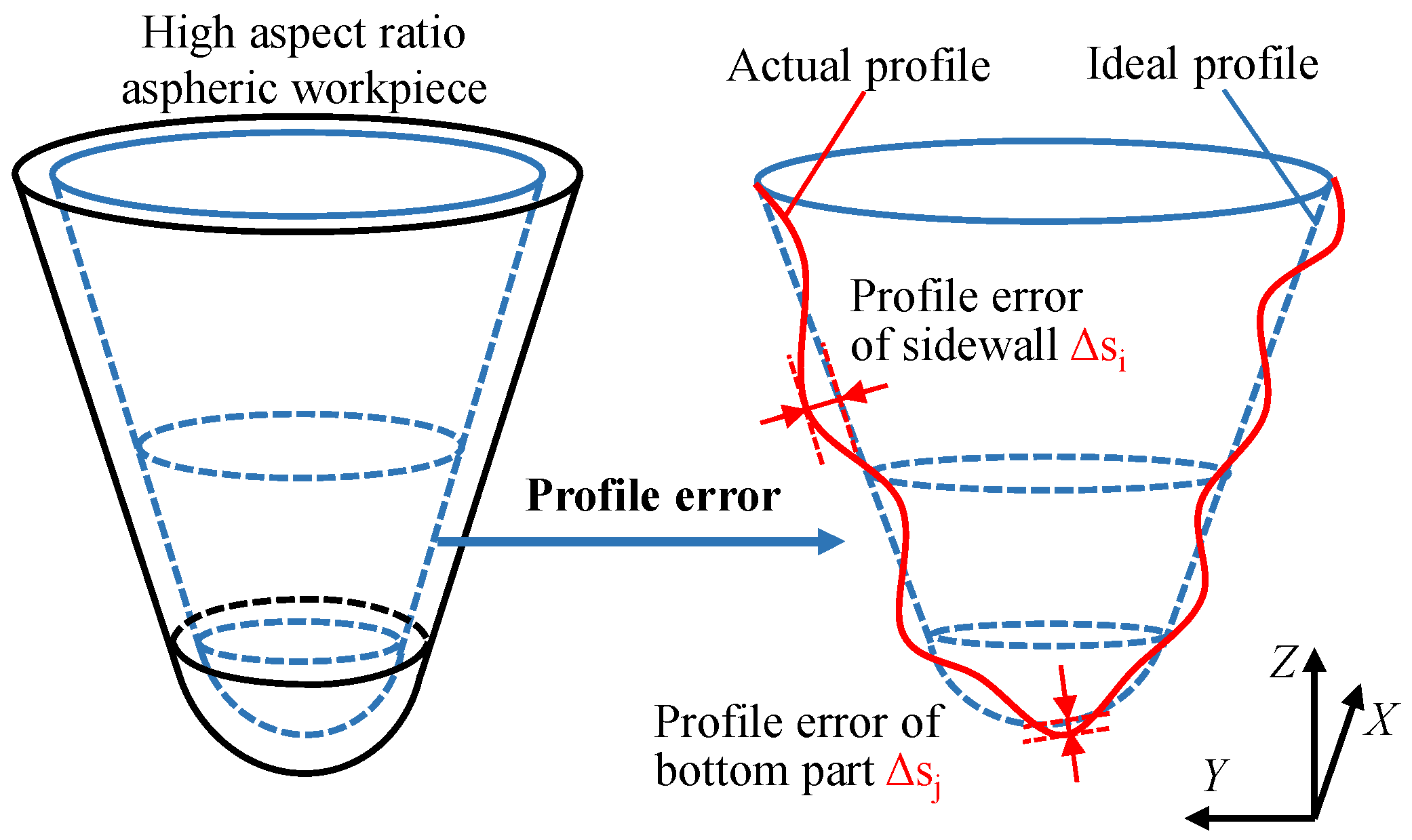
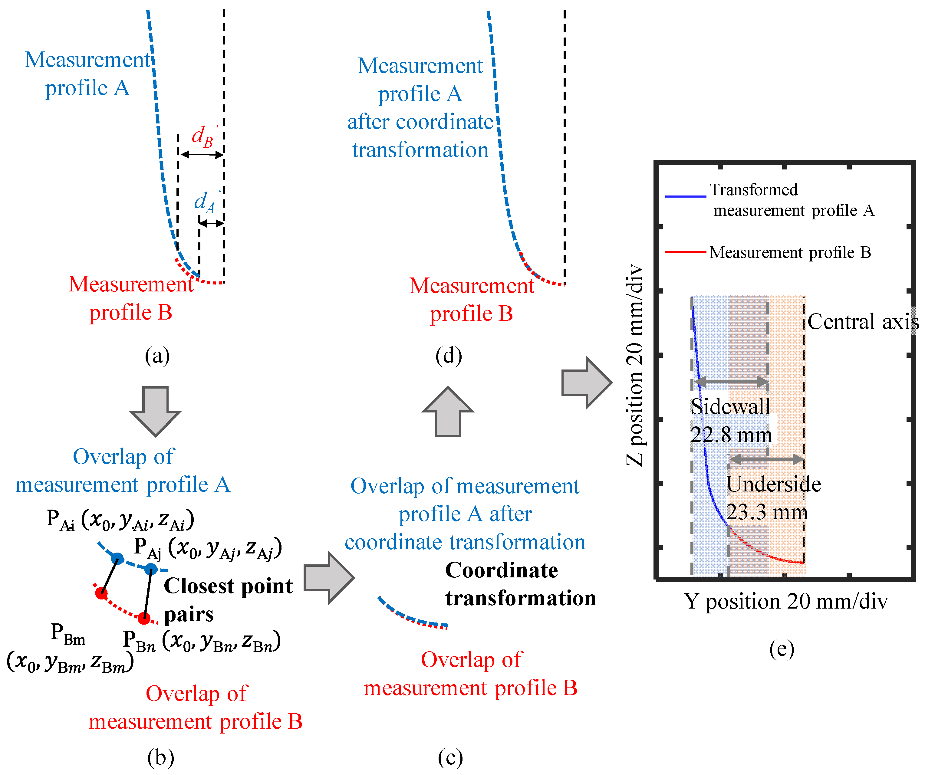
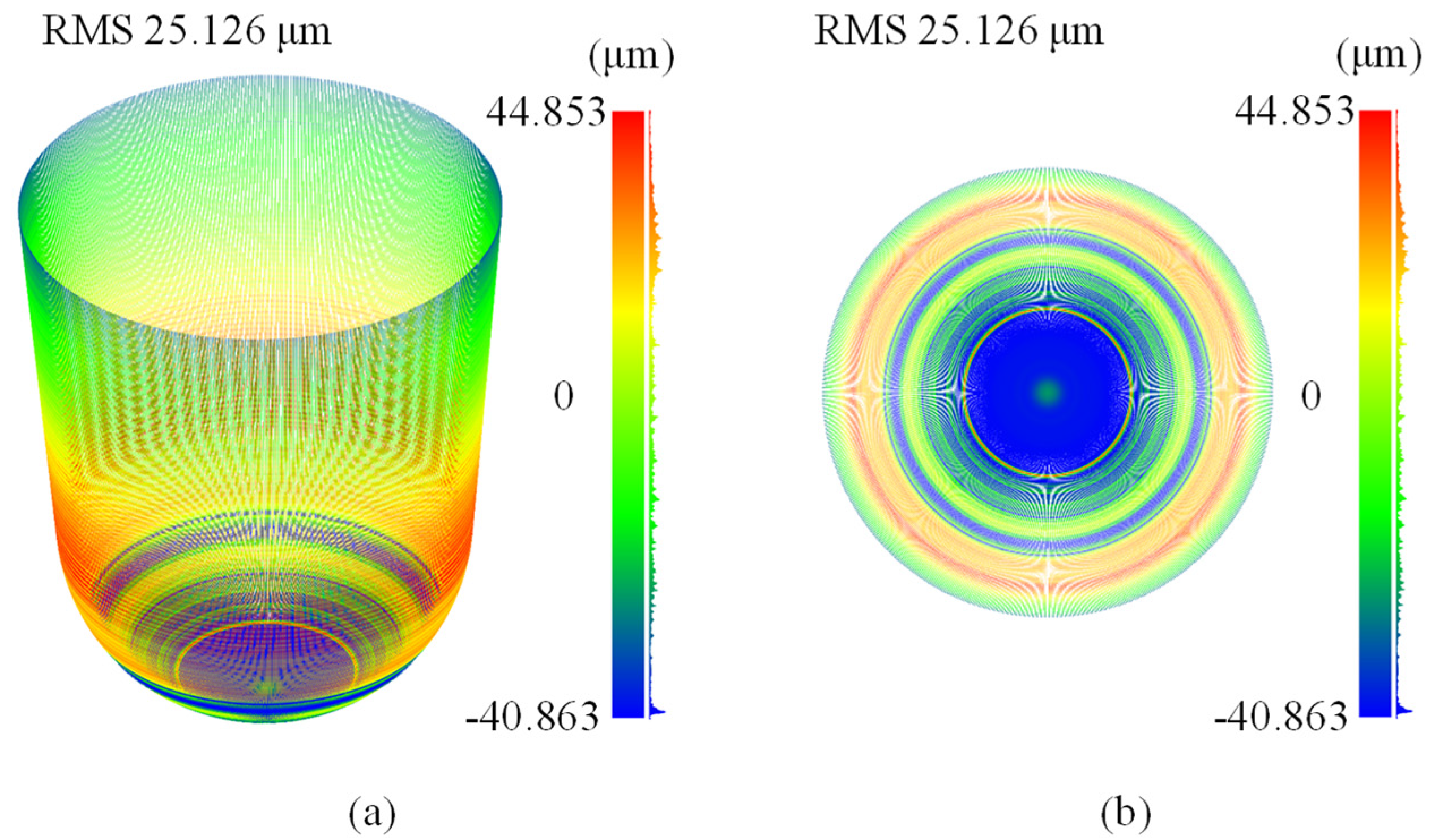
4.3. Data Processing and Analysis

First of all, using the interpolation algorithm, the motion errors of the Z-slide and the Y-slide were applied to compensate for the measurement results. As described in Section 3.1, the measurement of the lateral gauge could not represent the inner profile because of the influence of the shape of the probing sphere of the gauge probe. The trajectory of the center of the probing sphere of the lateral gauge could be obtained by the following equations:
y b a l l i = y s l i d e i + S l a t e r a l i
z b a l l i = z s l i d e i + h l a t e r a l i
h l a t e r a l i = f ( S l a t e r a l i )
where yballi and zballi are the y position and the z position of the center of the lateral gauge, respectively, yslideli and zslideli are the position of the Y-slide and the position of the Z-slide, respectively, Slaterali is the output of the lateral gauge and hlaterali is the corresponding vertical displacement of the probing sphere obtained according to Figure 5b. Then, an algorithm was applied to evaluate the real sidewall of the inner profile of the workpiece by removing the influence of the probing sphere shape. The evaluation results are shown in Figure 17a. According to the geometric relationship, we could obtain the coordinates of the sidewall profile of the inner part of the workpiece from the trajectory of the center of the probing sphere:
y A i = y A i r A i · cos ( θ A i )
z A i = z A i r A i · sin ( θ A i )
θ A i = arctan ( k A i )
where yAi′ and zAi′ are the y and z coordinates of the side of the inner profile, respectively, yAi and zAi are the y and z coordinates of the center of the probing sphere of the lateral gauge, respectively, rAi is the radius of the probing sphere of the gauge, kAi is the slope of the trajectory of the center of the probing sphere at the measuring point, and θAi is the inclination of the slope of the trajectory of the probing sphere. The results of the compensation algorithm of the sidewall of the inner profile are presented in Figure 17b. Similarly, the trajectory of the probing sphere of the axial gauge could be obtained from the coordinates of the slides and the output of the axial gauge. Then, the underside part of the inner profile was calculated using a similar compensation algorithm based on the trajectory of the probing sphere of the axial gauge and the roundness error obtained from Figure 14b. The results of the compensation algorithm of the underside of the inner profile are presented in Figure 17d. Finally, we applied a point cloud registration algorithm [24] to stitch the sidewall measured by the lateral gauge and the bottom part measured by the axial gauge to form an entire inner profile of the high aspect ratio aspheric workpiece, as shown in Figure 18. The overlap of the profiles measured by the lateral gauge and the axial gauge was determined through the moving range of the Y-slide, as shown in Figure 18a. Then the algorithm was applied to find the closest point pairs between the two overlap areas, and a transformation matrix was calculated based on the coordinates of the closest point pairs. The overlap area measured by the lateral gauge was then transformed through the calculated transformation matrix, and the average distance of the transformed closest point pairs was obtained. The procedure was repeated several times until the average distance was within a threshold of 100 nm, and the final transformation matrix was marked. Finally, the profile measured by the lateral gauge was transformed through the marked transformation matrix, and the entire inner profile was stitched. The stitched inner profile is presented in Figure 18e, and the mean stitching error was evaluated to be 87 nm according to the final average distance of the closest point pairs, meeting the requirement of micrometer measurement accuracy. For a clearer view of the measured inner profile, a three-dimensional inner profile error is represented by rotating the stitching profile around the central axis of the high aspect ratio aspheric workpiece, as shown in Figure 19a,b. The machining error has an RMS (root-mean-square) value of 25.126 μm. The error distribution is mainly considered to be caused by the manufacturing error of the machine tool. The machining error of the upper part is relatively small while it becomes larger when the machine tool processes the bottom part, which might be influenced by the stiffness of the machine tool. The radius of the bottom sphere is evaluated as 29.5923 mm, and the roundness is evaluated as 0.4808 mm. The steepness of the sidewall is evaluated as 84.9671°, and the straightness is evaluated as 0.2794 mm. It should be noted that the above results are calculated based on the overall inner profile after stitching.
Furthermore, the results obtained by the measurement system were verified by comparing with the measurement results obtained by using a coordinate measurement machine (CMM) (Hexagon Bridge-explorer 060806), which has a qualified accuracy of 2.9 μm with a standard test. Since the employed CMM could not measure the bottom part of the inner profile of the workpiece due to its relatively large probe, only the result of the upper part of the inner profile was compared. The difference between the profile measured by the proposed measurement system and that of CMM is presented in Figure 20b. The peak-to-valley value of the difference was evaluated to be about ±1.350 μm. The comparison result confirms the reliability of the proposed method for the evaluation of the inner profile of the high aspect ratio aspheric workpiece.

5. Conclusions

In summary, an accurate inner profile measurement and geometric parameters evaluation method for a high aspect ratio aspheric workpiece using two measuring probes is proposed. The geometric parameters such as the radius of the bottom spherical shape as well as the steepness and straightness of the steep sidewall can be successfully evaluated. A lateral displacement gauge is used to measure the steep sidewall of the inner profile, and an axial displacement gauge is used to measure the deep underside of the inner profile of the workpiece. To qualify the measurement accuracy, the systematic errors associated with the measurement procedure, including the miscalibration, misalignment and the roundness error of the gauge probes, as well as the slide motion error of the four-axis motion platform, are all evaluated and separated from the measurement results. The measured profile is evaluated after making an accurate alignment of the probes and workpiece as well as compensation of the slide motion error and probing sphere roundness error. To obtain the entire inner profile of the workpiece, a point cloud registration algorithm was applied to stitch the inner sidewall profile measured by the lateral gauge and the inner underside profile measured by the axial gauge.
To verify the performance of the proposed measurement system and the methods, the inner profile error of a high aspect ratio aspheric workpiece with a maximum inner radius of 40 mm, a maximum inner depth of 140 mm and a steep sidewall angle approaching 85°(conicity of 5.11°) was evaluated in experiments. The radius of the bottom sphere was evaluated as 29.5923 mm, and the roundness was evaluated as 0.4808 mm. The steepness of the sidewall was evaluated as 84.9671°, and the straightness was evaluated as 0.2794 mm. Some of the experimental results are compared with that of a coordinate measuring machine (CMM). The comparison result, which has a difference of about ±1.350 μm, has verified the feasibility of the proposed measurement system. In addition, it is also noted that the measurement can be performed by integrating the two-probe measuring system to a commonly used multi-axis motion stage instead of using the state-of-art CMM, which is thus potential for on-machine measurement of the high aspect ratio aspheric part. The advantage of the proposed method is that the inner and outer surfaces of the high aspect ratio aspheric workpiece can be assessed accurately with high compatibility for on-machine measurement. The integration of the on-machine measurement and the generalization of the measurement for other parts with different forms will be considered for potential improvements. Future works include comprehensive uncertainty analysis of the results such as the repeatability error and the misalignment error of the two probes, compensation of the machined surface using the evaluation results, measuring other high aspect ratio parts by using the developed two-probe system, as well as automation of the measurement system to reduce the uncertainties in alignment and measurement procedure.

Author Contributions

Conceptualization, Y.-L.C., B.-F.J. and X.X.; methodology, Y.-L.C. and P.H.; software, P.H.; validation, P.H.; formal analysis, P.H.; investigation, P.H. and W.-H.Z.; resources, P.H. and W.-H.Z.; data curation, P.H.; writing—original draft preparation, Y.-L.C. and P.H.; writing—review and editing, Y.-L.C. and X.X.; visualization, Y.-L.C. and X.X.; supervision, Y.-L.C.; project administration, Y.-L.C. and B.-F.J.; funding acquisition, Y.-L.C. and B.-F.J. All authors have read and agreed to the published version of the manuscript.

Funding

This research is supported by the National Key R&D Program of China (Grant No. 2020YFB2007600), the National Natural Science Foundation of China (Grant No. 51975522), and the Ministry of Industry and Information Technology’s Manufacturing High-quality Development Project TC200H02J. B.-F.J. appreciates the support from the National Natural Science Foundation of China (Grant Nos. 52035013 and U1709206), the Science Fund for Creative Research Groups of National Natural Science Foundation of China (No. 51821093), and the Zhejiang Provincial Key R&D Program of China (No. 2018C01065).

Institutional Review Board Statement

Not applicable.

Informed Consent Statement

Not applicable.

Data Availability Statement

Not applicable.

Conflicts of Interest

The authors declare no conflict of interest.

References

  1. Keaveney, S.; Connolly, P.; Ahearne, E.; Byrne, G. Investigation of a multi-cone variant of the standard cone frustum test for 5-axis machine tools. Procedia CIRP 2014, 14, 317–322. [Google Scholar] [CrossRef] [Green Version]
  2. Chen, B.; Li, S.; Deng, Z.; Guo, B.; Zhao, Q. Grinding marks on ultra-precision grinding spherical and aspheric surfaces. Int. J. Precis. Eng. Manuf.-Green Technol. 2017, 4, 419–429. [Google Scholar] [CrossRef]
  3. Kang, Y.; Li, H.; Diao, X.; Zhang, H. The interferometric method for measuring the generatrix straightness of high precision cone. AOPC 2015 Opt. Test Meas. Equip. 2015, 9677, 967720. [Google Scholar]
  4. Lu, J.P.; Tang, S.Y.; Yan, Y.; Zhang, F.P.; Butt, S.I. Research on assembly quality evaluation based on Markov chain. In Proceedings of the 2009 IEEE International Conference on Industrial Engineering and Engineering Management, Hong Kong, China, 8–11 December 2009; Volume 2, pp. 1366–1370. [Google Scholar]
  5. Zhang, Q.; Wang, K.; Dong, R.; Fan, W.; Lu, W.; Wang, Y. Experimental research on propulsive performance of the pulse detonation rocket engine with a fluidic nozzle. Energy 2019, 166, 1267–1275. [Google Scholar] [CrossRef]
  6. Zhang, L.; Huang, Z.; Zhao, J.; Zhang, S.; Zhou, M. Research on motion generation for machining axisymmetric aspheric concave surface. Appl. Mech. Mater. 2012, 120, 129–133. [Google Scholar] [CrossRef]
  7. Usuki, K.; Kitayama, T.; Matsumura, H.; Kojima, T.; Uchikoshi, J.; Higashi, Y.; Endo, K. Profile measurement of concave spherical mirror and a flat mirror using a high-speed nanoprofiler. Nanoscale Res. Lett. 2013, 8, 231. [Google Scholar] [CrossRef] [PubMed] [Green Version]
  8. Chen, Y.L.; Chen, F.; Li, Z.; Zhang, Y.; Ju, B.; Lin, H. Three-axial cutting force measurement in micro/nano-cutting by utilizing a fast tool servo with a smart tool holder. CIRP Ann. 2021, 70, 33–36. [Google Scholar] [CrossRef]
  9. Gao, W.; Haitjema, H.; Fang, F.Z.; Leach, R.K.; Cheung, C.F.; Savio, E.; Linares, J.M. On-machine and in-process surface metrology for precision manufacturing. CIRP Ann. 2019, 68, 843–866. [Google Scholar] [CrossRef] [Green Version]
  10. Fan, K.C.; Li, R.J.; Xu, P. Design and Verification of Micro/Nano-Probes for Coordinate Measuring Machines. Nanomanuf. Metrol. 2019, 2, 1–15. [Google Scholar] [CrossRef]
  11. Osawa, S.; Busch, K.; Franke, M.; Schwenke, H. Multiple orientation technique for the calibration of cylindrical workpieces on CMMs. Precis. Eng. 2005, 29, 56–64. [Google Scholar] [CrossRef]
  12. Demir, A.G. Micro laser metal wire deposition for additive manufacturing of thin-walled structures. Opt. Lasers Eng. 2018, 100, 9–17. [Google Scholar] [CrossRef]
  13. Chen, Y.L.; Machida, Y.; Shimizu, Y.; Matsukuma, H.; Gao, W. A stitching linear-scan method for roundness measurement of small cylinders. CIRP Ann. 2018, 67, 535–538. [Google Scholar] [CrossRef]
  14. Weckenmann, A.; Peggs, G.; Hoffmann, J. Probing systems for dimensional micro- and nano-metrology. Meas. Sci. Technol. 2006, 17, 504–509. [Google Scholar] [CrossRef]
  15. Fang, F.Z.; Zhang, X.D.; Weckenmann, A.; Zhang, G.X.; Evans, C. Manufacturing and measurement of freeform optics. CIRP Ann. Manuf. Technol. 2013, 62, 823–846. [Google Scholar] [CrossRef]
  16. Claverley, J.D.; Leach, R.K. A vibrating micro-scale CMM probe for measuring high aspect ratio structures. Microsyst. Technol. 2009, 16, 1507–1512. [Google Scholar] [CrossRef]
  17. Manske, E.; Jäger, G.; Hausotte, T.; Fül, R. Recent developments and challenges of nanopositioning and nanomeasuring technology. Meas. Sci. Technol. 2012, 23, 074001. [Google Scholar] [CrossRef]
  18. Stoebener, D.; Dijkman, M. An Ultrasound In-Process-Measuring System to Ensure a Minimum Roundness Deviation for Rings During Turning. CIRP Ann. Manuf. Technol. 2007, 56, 513–516. [Google Scholar] [CrossRef]
  19. Lian, M.; Liu, H.; Zhang, T.; Bo, Q.; Li, T.; Wang, Y. Ultrasonic on-machine scanning for thickness measurement of thin-walled parts: Modeling and experiments. Int. J. Adv. Manuf. Technol. 2019, 104, 2061–2072. [Google Scholar] [CrossRef]
  20. Jin, L.; Miyatsu, N.; Kondoh, E.; Gelloz, B.; Kanazawa, N.; Yoshizawa, T. Measurement of diameter of cylindrical openings using a disk beam probe. Opt. Rev. 2018, 25, 656–662. [Google Scholar] [CrossRef]
  21. de Jesús Ortiz-González, A.; Martínez-García, A.; Pascual-Francisco, J.B.; Rayas-Álvarez, J.A.; de Jesús Flores-García, A. 3D shape and strain measurement of a thin-walled elastic cylinder using fringe projection profilometry. Appl. Opt. 2021, 60, 1349. [Google Scholar] [CrossRef]
  22. Adamczak, S.; Zmarzły, P.; Janecki, D. Theoretical and practical investigations of V-block waviness measurement of cylindrical parts. Metrol. Meas. Syst. 2015, 22, 181–192. [Google Scholar] [CrossRef]
  23. Hansen, H.N.; Carneiro, K.; Haitjema, H.; De Chiffre, L. Dimensional micro and nano metrology. CIRP Ann. Manuf. Technol. 2006, 55, 721–743. [Google Scholar] [CrossRef]
  24. Yang, J.; Li, H.; Campbell, D.; Jia, Y. Go-ICP: A Globally Optimal Solution to 3D ICP Point-Set Registration. IEEE Trans. Pattern Anal. Mach. Intell. 2016, 38, 2241–2254. [Google Scholar] [CrossRef] [PubMed] [Green Version]
  25. Lee, J.C.; Shimizu, Y.; Gao, W.; Oh, J.; Park, C.H. Precision evaluation of surface form error of a large-scale roll workpiece on a drum roll lathe. Precis. Eng. 2014, 38, 839–848. [Google Scholar] [CrossRef]
Figure 1. Schematic of the constructed two-probe measurement system.
Applsci 12 06628 g001
Figure 2. Schematic of error of inner profile of the high aspect ratio aspheric workpiece.
Applsci 12 06628 g002
Figure 3. Measurement procedure with the two measuring probes and profile stitching.
Applsci 12 06628 g003
Figure 4. Schematic of the misalignment, roundness errors and motion errors associated with the measurement system.
Applsci 12 06628 g004
Figure 5. Schematic of calibration for the measurement of the lateral displacement gauge. (a) Horizontal calibration for the lateral probe; (b) vertical calibration for the lateral probe.
Applsci 12 06628 g005
Figure 6. Schematic of tilt alignment of the measuring probes. (a) Schematic of the lateral probe (probe A) tilt alignment; (b) schematic of the axial probe (probe B) tilt alignment.
Applsci 12 06628 g006
Figure 7. Schematic of sphere roundness calibration of the measuring probes. (a) Schematic of measuring sphere roundness calibration for lateral probe (probe A); (b) schematic of measuring sphere roundness calibration for axial probe (probe B).
Applsci 12 06628 g007
Figure 8. Schematic of tilt alignment of the high aspect ratio aspheric workpiece. (a) Schematic of marking the farthest point; (b) tilt alignment of the high aspect ratio aspheric workpiece.
Applsci 12 06628 g008
Figure 9. Schematic of slide motion error calibration. (a) Preparation for Z-slide motion error calibration; (b) Z-slide motion error calibration; (c) preparation for Y-slide motion error calibration; (d) Y-slide motion error calibration.
Applsci 12 06628 g009
Figure 10. Photograph of the experimental setup.
Applsci 12 06628 g010
Figure 11. Schematic of the measurement procedure for inner profile surface of the high aspect ratio aspheric workpiece.
Applsci 12 06628 g011
Figure 12. Experimental results of calibration of the lateral displacement gauge (probe A). (a) Horizontal calibration of the lateral displacement gauge (probe A); (b) vertical calibration of the lateral displacement gauge (probe A).
Applsci 12 06628 g012
Figure 13. Experimental results of the tilt alignments of the lateral and axial displacement gauges. (a) Tilt alignment of the lateral displacement gauge (probe A); (b) tilt alignment of the axial displacement gauge (probe B).
Applsci 12 06628 g013
Figure 14. Experimental results of probing sphere roundness calibration for the lateral and axial displacement gauges. (a) Sphere roundness calibration of the lateral displacement gauge (probe A); (b) sphere roundness calibration of the axial displacement gauge (probe B).
Applsci 12 06628 g014
Figure 15. Experimental results of the calibration of the Y/Z-slide motion error. (a) Calibration of the Z-slide motion error; (b) calibration of the Y-slide motion error.
Applsci 12 06628 g015
Figure 16. Experimental results of the tilt alignments of the high aspect ratio aspheric workpiece.
Applsci 12 06628 g016
Figure 17. Schematic and experimental results of evaluating the inner profile of the high aspect ratio aspheric workpiece. (a) Schematic of evaluating the inner sidewall profile; (b) experimental results of evaluating the inner sidewall profile; (c) schematic of evaluating the inner underside profile; (d) experimental results of evaluating the inner underside profile.
Applsci 12 06628 g017
Figure 18. Schematic and experimental results of the point cloud registration algorithm for inner profile stitching. (a) Schematic of obtaining an overlap measurement profile of probe A and probe B; (b) schematic of finding the closest point pairs of the point cloud registration algorithm; (c) schematic of coordinate transformation of the point cloud registration algorithm; (d) schematic of coordinate transformation for Measurement profile A; (e) experimental results of the point cloud registration algorithm for inner profile stitching.
Applsci 12 06628 g018
Figure 19. Three-dimensional machining error of the inner profile of the high aspect ratio aspheric workpiece. (a) Three-dimensional machining error of the high aspect ratio aspheric workpiece compared with the theory profile; (b) top view of three-dimensional machining error of the high aspect ratio aspheric workpiece.
Applsci 12 06628 g019
Figure 20. Measurement results of the inner profile of the high aspect ratio aspheric workpiece. (a) Comparison between theory profile and measurement profile; (b) measurement error of the high aspect ratio aspheric workpiece compared with the CMM measurement.
Applsci 12 06628 g020
Publisher’s Note: MDPI stays neutral with regard to jurisdictional claims in published maps and institutional affiliations.

