Article

Intelligent Air Cutting Monitoring System for Milling Process

1
Department of Mechanical Engineering, National Chung Hsing University, Taichung 40227, Taiwan
2
Department of Mechanical Engineering, Chung Yuan Christian University, Taoyuan 320314, Taiwan
3
R & D Center for Smart Manufacturing, Chung Yuan Christian University, Taoyuan 320314, Taiwan
*
Author to whom correspondence should be addressed.
Appl. Sci. 2022, 12(9), 4137; https://doi.org/10.3390/app12094137
Submission received: 22 March 2022 / Revised: 15 April 2022 / Accepted: 18 April 2022 / Published: 20 April 2022
(This article belongs to the Special Issue Precision Manufacturing and Intelligent Machine Tools)

Abstract

:
This research proposes a method for auto-monitoring the air cutting condition of a machining process, so the air cutting time can be further improved to enhance the machining efficiency. A two-way data communication module with a CNC controller was established to achieve real-time monitoring and control function via TCP/IP protocol. The module enables the identification of the executing NC block and the cutting time during machining. The spindle load current and cutting vibration signals were used to on-line diagnose the cutting state (effective cutting or air cutting), and their associated NC codes were identified and recorded at the same time, based on the executing NC block in the CNC controller. An algorithm adopting this state change information to determine effective cutting time and air cutting time was developed and used to build an intelligent air cutting monitoring system, with a friendly human–machine interface. The system can detect air cutting time, effective cutting time, machine idle time, as well as the total machining time to improve the air cutting time to enhance the machining efficiency. Verification experiments were conducted, and the results showed the proposed method can accurately detect the air cutting occurrence and its associated NC blocks in the NC program.

1. Introduction

The evolution of manufacturing toward intelligent manufacturing, such as Industry 4.0, creates new challenges to high-quality and efficient manufacturing. Machining accuracy, machining efficiency, and tool life are the key factors for optimization in manufacturing. The machining parameters have a direct effect on the tool life, machining accuracy, and machining efficiency. Therefore, the design of cutting parameters and cutting paths are very important. Meanwhile, the NC (Numeric Control) machining process, as the main part of producing the product, requires a high-efficiency and intelligence level in NC machining process planning. Recently, the commercial CAM (Computer-Aided Manufacturing) software has come into wide use, but the process analysis and decision making still depend on the knowledge and experience of designers. Numerous problems, such as inefficient process planning and time-consuming preparation, occur as a consequence. Currently, reuse technology is utilized for the NC machining process, including group technology and machining process template. Jong et al. [1] developed an automatic process planning method that integrates feature recognition and group technology. Huang et al. [2] studied the NC process reuse method by using 3D CAD (Computer-Aided Design) model and CAM model data mining. This approach explores the NC process-parameter-driven characteristics of similar features through the analysis and mining of existing process data. However, it is difficult to make the micro process and macro process compatible, and requires many considerable adjustments due to the reusable NC process characteristics of multiple parts, manufacturing heterogeneity, machining parameter variability, and subpart level, thereby compromising the effectiveness of NC process reuse. The optimization approach of the NC machining process has been studied by Xu et al. [3], where an annealing algorithm was proposed and simulated to obtain the shortest tool path. Similarly, Zhang et al. [4] optimized the cutting sequence in NC machining by developing a mathematical model for the shortest tool path. This method is limited for the machining of independent features and, therefore, limited in improving the efficiency of the overall machining. When the features in a subpart come together and feature recognition technology is used to create machining parameters, many air cutting paths may occur. The different technique for reducing the time of the NC program was investigated in previous studies [5,6]. Nishida et al. [7] proposed a method to generate a tool path based on the 3D CAD model and eliminate the air cutting by modifying the tool path. As seen, the NC machining process created by CAM software is not optimal, many air cutting paths may be produced, and it is difficult to improve machining efficiency by modifying the cutting path due to the reliability considerations.
Non-effective cutting will occur during the machining process. This is perhaps because the distance between tool position and workpiece is too far or due to groove occurrence during the machining processes. Besides, ballscrew error, backlash error or position error, etc., will also increase the non-effective cutting motion distance. The error caused by the machine itself leads to excess or insufficient moving distance, so creates an inconsistent product or non-standard size. If the product is overcut then it will be scrapped, resulting in not only a financial loss but also a waste of time. When the problem is discovered after mass production, it causes huge losses. Since the cutting fluid is often used in the machining process, it is impossible to observe overcutting or undercutting during processing. Meanwhile, if the air cutting of each section during the machining process can be known, it can help to know whether there is machining abnormality or air cutting, and also the abnormality can be modified and optimized. Therefore, the abnormality can be detected to reduce losses and improve the machining efficiency.
The monitoring of the machining process is required to investigate the air cutting in the machining process. Several works related to machining process monitoring have been reported. Dimla [8] reviewed several device-monitoring methods for observing tool wear. This showed that tool wear could be monitored by using acoustic emission (AE), cutting force, and vibration signals. Duspara et al. [9] described a mathematical model of fast Fourier transformation, and used it for tool wear monitoring based on acoustic emission signal. Mohanraj et al. [10] reviewed different methods of tool condition monitoring systems, including the use of acoustic emission, vibration, cutting force, and thermal. Jemielniak et al. [11] used acoustic emission and cutting force signal for tool condition monitoring in micro-milling. It showed that AE signal was strong and had very short reaction time to the tool–workpiece contact, which makes it a very good method for detecting the contact and monitoring the integrity of the cutting process. Liang et al. [12] collected the power data during dynamic machining processes to diagnose and detect anomalies. Xu et al. [13] used indirect data from CNC machines, such as spindle power, to automatically monitor tool breakage. The spindle power data were analyzed according to the relationship between the spindle power and NC block number to effectively and accurately detect tool breakage. Shrivastava et al. [14] used vibration signal to monitor the chatter signal, then combined it with response surface methodology for predicting the tool chatter. Drouillet et al. [15] predicted the tool life by using machine spindle power and a neural network technique. Experiments with different spindle speeds and spindle power were recorded, then the neural network curve fitting with different training functions was applied to the root mean square power values to predict the tool life. Patra et al. [16] proposed an Artificial Neural Network method with input parameters of spindle motor current, drill diameter, spindle speed, and feed rate to predict drill flank wear. The experiment results showed that the accuracy prediction using a neural network was better than that using a regression model. Emec et al. [17] proposed a method that used electrical power for online fault monitoring in machine tools. The major advantage was the measurement did not interrupt or delay the machining processes. Wang et al. [18] approached a hybrid optimization method to find optimal cutting parameters, which resulted in shorter machining time and lower power consumption for the milling process. The experimental results showed that the proposed method can effectively improve the efficiency and reduce machining time and electrical power consumption. Similarly, Chen et al. [19] considered electrical energy for machining efficiency. Song [20] used the cutting process and the corresponding time series model to measure the vibration signal. It can predict real-time processing status through theoretical analysis and experiment methods. Cus et al. [21] proposed intelligent online monitoring and a General Algorithm optimization system. The data were collected via sensor and Labview, then the experiment was carried out to verify the effectiveness of this method.
In the previous study, the researchers investigated the air cutting path using a CAD model and the micro and macro process to generate NC machining; however, the air cutting path may occur, and also the air cutting occurrence during machining processes cannot be detected in the beginning. In this study, an intelligent air cutting monitoring system is proposed to improve the machining efficiency. The spindle current load, cutting vibration, and NC processing during the machining processes are measured and monitored in real time. Furthermore, an algorithm adopting these change states to determine effective cutting or air cutting was developed. An intelligent air cutting monitoring system with human–machine interface was built using C# language program. The system can detect air cutting time, effective cutting time, machine idle time, as well as calculate total machining time. The experiments and verification were conducted to verify the proposed method. The result can be used as a basis for optimizing the machining path and minimizing air cutting time.
The structure of this paper is as follows: In Section 2, the characteristics of spindle load current and cutting vibration are analyzed to explore the potential air cutting occurrence in the machining process, and the air cutting monitoring system is elucidated. In Section 3, we explain the design and feature function of the air cutting monitoring human machine interface (HMI). In Section 4, the detailed experiment design, cutting parameters, and condition are described. In Section 5, we explain and discuss the results of the experiment and verification. Finally, the conclusions of this study are presented in Section 6.

2. Monitoring Method

Understanding the air cutting of NC machining can help users reduce unnecessary time used air cutting during the machining, and improve the machining efficiency and machine utilization rate. In this research, the G code in the NC program is analyzed, and the change of machine spindle load current and the cutting vibration signal are measured to develop an intelligent air cutting monitoring module. The architecture of the air cutting monitoring system is shown in Figure 1. The Fanuc Open CNC (Computer Numeric Control) API was used to establish a two-way real-time information communication system with a CNC controller. The monitoring system was connected to the Fanuc controller via Ethernet and servbox to capture real-time processing information, such as machining status, spindle load, and current execution NC program for auxiliary diagnosis. To measure the cutting vibration, three single-axis vibration accelerometer sensors made by PCB Piezotronics (model 353B15 and data acquisition (DAQ) NI USB-4431) made by National Instruments Corp. were used. The vibration sensors were mounted on the vise with magnetic mount method to measure X-, Y-, and Z-axis vibration. The sampling rate of 10,240 Hz was set for experiment, and the 1024 data were collected every 0.1 s, then we calculated its root mean square (RMS). By using spindle load and vibration signal, the cutting state and no-cutting state are clear and easy to differentiate, so these two signals are used as the judgment basis. The spindle load and vibration of the machine idle condition are measured and used as the diagnosis threshold.
Generally, the G code command for the cutting process is G01, G02, and G03. Another G00 code is mainly used for rapid moving position, and the time for this movement is called air cutting time. To better differentiate air cutting under individual cutting commands, the NC code is identified by using the regular expression method. When the machining condition is under one of three cutting NC codes, the judgment is performed to determine the entry of the cutting status and the current time of the computer is recorded.
The spindle load is displayed on the control panel with the letter “L 0%”, which represents the spindle load is 0%. For example, the spindle load current when idle is 0%, and this value is used as the initial value of the spindle load. When the spindle load current is greater than 0% during the machining process, it indicates that the cutting state and the current time are recorded. On the other hand, when the spindle load current changes back from the state of greater than 0% to 0%, it indicates the no-cutting state, and the current time is recorded for the subsequent processing time calculation usage.
Since the original vibration signal fluctuates between positive and negative, it is difficult to see the characteristics directly. Therefore, the root mean square (rms) of the vibration signal is calculated and used to monitor the cutting vibration signals, so the cutting state can be differentiated clearly. After the rms processing, the machine idle rms vibration value is multiplied by the magnification and becomes greater than the maximum machine idle original vibration value to avoid system misjudgment. For example, if the machine idle original vibration value is in the range of 0.01 g to 0.02 g, the recommended magnification value is 2 or more. The air cutting diagnosis and time recording are as follows:
  • Identification of G00, G01, G02, and G03. The real-time information acquisition module collects the current execution NC code block from the CNC controller. Then, Regular Expression method is used to identify the NC code and search the matching G code. For example, “G01.{1,}” means “G01” to identify G01, “.” to identify a character, and “{1,}” to identify the number. Table 1 shows the regular expression characteristics used in this research.
2.
Machining time calculation. The machining time of each NC machining section is obtained according to the time length of G code change. For example, when the executing block is G01, the current time is recorded as T1. When the executing block changes to another G code (no matter G00, G02, or G03), the current time is recorded as T2. Thereby, this section G01 machining time is T2–T1. Similarly, this is the section machining time calculation method for G00, G02, and G03.
3.
Effective cutting time and air cutting time calculation. Take vibration signal judgment as an example. When the executing block is G01, the system will evaluate the vibration signal. Once the vibration value is greater than the initial vibration value, it will be judged as actual cutting, and the current time is recorded as L1. When the vibration value drops back from the cutting vibration value to the initial vibration value, it will be judged as no cutting, and the current time is recorded as L2. Thereby, the effective cutting time of this G01 section is L2–L1. The air cutting time of the G01 section can be obtained by subtracting the effective cutting time (L2–L1) from the total machining time (T2–T1), as shown in Figure 2. The calculation method of cutting time and air cutting time of the G02 and G03 machining sections is the same as that of G01. Because the G00 is the G code for rapid moving and non-effective cutting, the machining time is counted as air cutting time.

3. Air Cutting Monitoring System

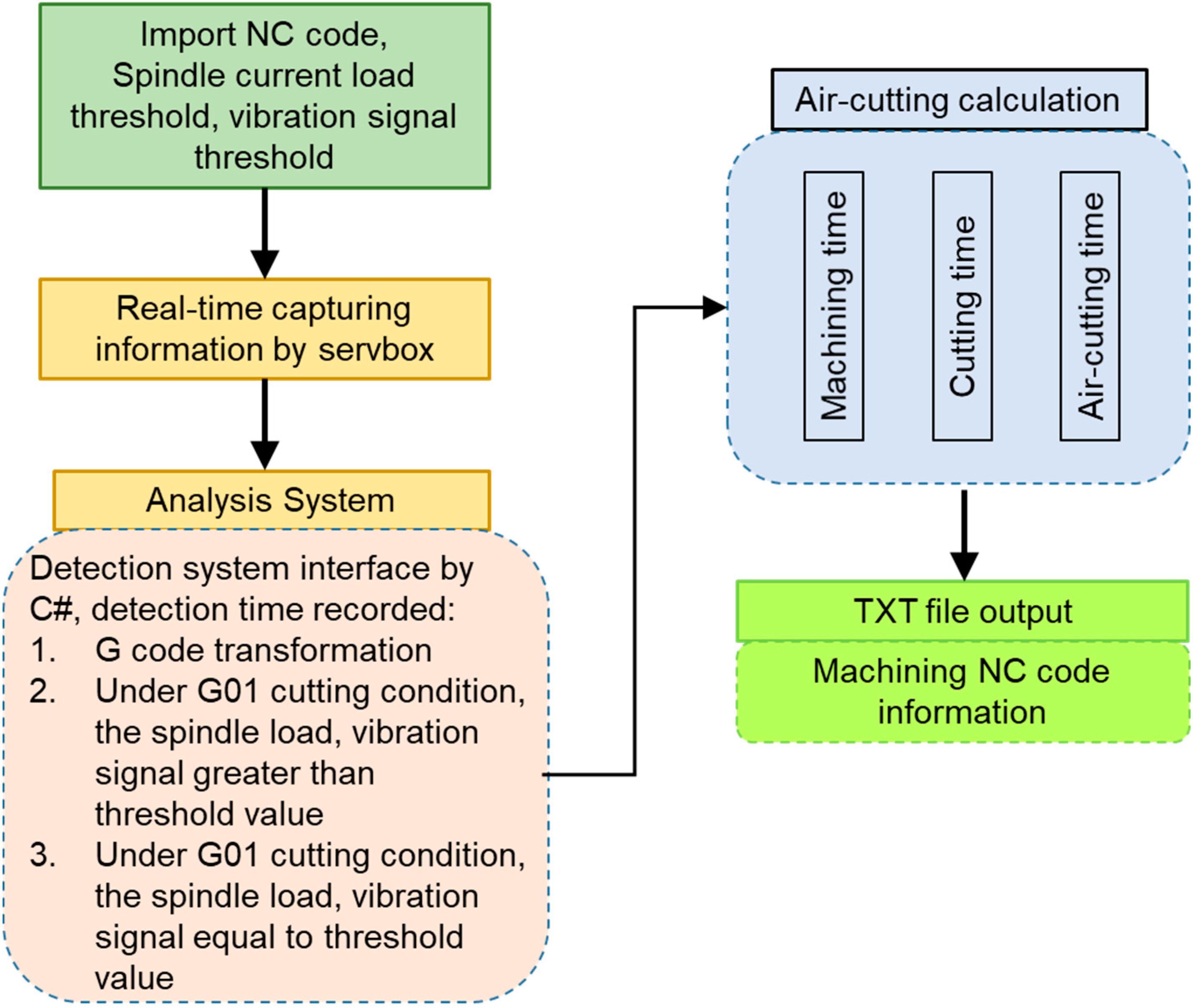
The Human Machine Interface (HMI) is designed and becomes the air cutting monitoring system. The system can detect real-time machining status (cutting/no-cutting) and calculate effective cutting time, air cutting time, and total machining time, as shown in Figure 3. The user needs to input spindle load, vibration threshold, and import NC machining program, then the system will capture the real-time spindle load, vibration signals, and NC machining. Subsequently, the signal and data are analyzed, then combined with the algorithms to perform cutting/no-cutting judgment. When the spindle load current value and vibration signal value are greater than the threshold value, and the current executing NC block is G01/G02/G03, then the system will judge as a cutting state. Meanwhile, the system will record the current time and the “Cutting” indicator in the HMI will change to a green color that indicates the machining status. On the other hand, when the spindle load current value and vibration signal value decrease from the cutting load value to the threshold value, where the vibration signal value is equal to the vibration threshold value, and the current executing NC block is G01/G02/G03, then the system will judge as a no-cutting state. Meanwhile, the system will record the current time and the “No Cutting” indicator in the HMI will change to green color. When the executing NC block is M30, which means that the machining is completed, the system will calculate all the recorded cutting time, air cutting time, and machining time, as shown in Figure 3. At the same time, the system exports the detailed information in txt file format, as shown in Figure 4.
The quality of measurement is important for the precision machining. However, there may be uncertainty in the measurement. The main uncertainty contributors are machine repeatability, accelerometer sensor repeatability, sampling strategy, DAQ, fitting and evaluation algorithm. The CNC vertical machining center TMV-720A with machine repeatability of ±7 μm was used in this study. The accelerometer sensor 353B15-PCB that was used in the experiment has non-linearity ≤1%. Besides, the NI DAQ USB-4431 internal frequency timebase accuracy is ±100 ppm.

4. Verification Experiments

4.1. Experiment Design

Experiments were designed to establish the monitoring threshold values by understanding the variation characteristics of the spindle load and cutting vibration during effective and ineffective cutting. With the function of NC code auto-identification and time calculation, the cutting state (effective cutting and air cutting) and its associated time can be monitored and recorded.
There are two diagnosis methods for air cutting monitoring: (1) use spindle load current as the judgment basis, (2) use the cutting vibration value as the judgment basis. Due to different cutting conditions, the cutting amount will affect the clarity of the change in the judgment signal. Generally, with the appropriate vibration accelerometer, the cutting vibration signal can better show the presence or absence of micro-cutting. Therefore, two different monitoring methods are proposed in the study.
The cutting parameter for the experiment based on spindle load judgment is shown in Table 2. An aluminum workpiece material with a dimension of 100 × 80 × 70 mm was used in this experiment. The Endmill tool with a diameter of 10 mm, three flutes, and tungsten carbide material was used. The straight-line cutting path along the Y-axis with 10 repetitions was carried out. The same cutting path (120 mm of moving along the Y-axis, cutting length is 100 mm) and same feed rate (1000 mm/min) were used to test the reproducibility and accuracy of the machining time monitoring result under the same cutting condition. Besides, it can be used to verify whether there is a problem in the real-time judgment and operation.
The cutting parameters for the experiment, based on vibration value judgment, are shown in Table 2. The workpiece material to be cut is medium carbon steel, with a dimension of 100 × 80 × 70 mm. The Endmill tool with a diameter of 10 mm, three flutes, and tungsten carbide material was used. The straight-line cutting path along the X-axis with three repetitions was carried out. In this experiment, a width of cut of 0.1 mm was chosen to test whether the proposed monitoring system can correctly monitor the air cutting during micro-cutting. The same cutting path (200 mm of moving along the X-axis, cutting length is 100 mm) and same feed rate (600 mm/min) was used to test the reproducibility and accuracy of the machining time monitoring result under the same cutting condition, and also to verify the correctness and reliability of the real-time judgment of the monitoring system.

4.2. Instrument and Data Acquisition

A CNC vertical machining center Dongtai TMV-720A with X, Y, Z-axis stroke 720 × 480 × 530 mm, spindle maximum speed 10,000 rpm, equipped with Fanuc controller was used in this experiment. The accelerometers 353B15-PCB piezotronics with a frequency range of 1–10 kHz and sensitivity of 10 mV/g were mounted on the vise, and the data acquisition (DAQ) NI USB-4431 with 102.4 kS/s simultaneous sampling rate was used to acquire and convert the vibration signals. Ethernet cable was used to connect the CNC controller and computer, then the NC machining and spindle load were captured via Servebox and stored in the computer.

5. Results and Discussion

5.1. Spindle Load Diagnosis Method

In the experiment, the cutting was performed 10 times in the same cutting path with 120 mm of Y-axis movement and a cutting length of 100 mm. The cutting feed rate was 1000 mm/min. This experiment used the spindle load current as monitoring information. The cutting parameters are shown in Table 2. Figure 5 and Figure 6 show the results after the air cutting monitoring is completed. As seen, the air cutting time of G00 (Figure 5) and machining time of G01 (Figure 6) results for 10 repetitions of the experiments are very reproducible. The mean and standard deviation were calculated to estimate the uncertainty of measurement. It showed that the mean, standard deviation, and uncertainty for G00 air cutting time were 2.39 s, 0.15 s, and 1.2%, respectively. Meanwhile, for G01 air cutting time, the mean, standard deviation, and uncertainty were 3.46 s, 0.23, and 1.2%. The mean, standard deviation, and uncertainty for G01 cutting time and machining time were 5.96 s, 0.16 s, 0.5% and 9.43 s, 0.17 s, 0.3%, respectively. Further, the deviation range of the measurement result is within one second. The main reason for this error is the delay in real-time judgment; however, the overall monitoring data are still very stable. Since the cutting feed rate is 1000 mm/min and the actual cutting length is 100 mm, the theoretical cutting time is 6 s, which is consistent with the data monitored by the system.

5.2. Vibration Signal Diagnosis Method

For the monitoring experiment, based on cutting vibration signals as the judgment basis, the experiment parameters are shown in Table 2. The accelerometer is installed on the vise, and the cutting path is the same as in the previous experiment. The experiment result data are shown in Table 3. It can be seen that the monitoring results of the three cuttings are similar. The mean, standard deviation, and uncertainty of cutting time, air cutting time, and machining time were 10.443 s, 0.048 s, 0.27%; 11.941 s, 0.046 s, 0.22%; 22.384 s, 0.016 s, 0.04%, respectively. The total machining time is about 22.4 s, and the cutting time is about 10.4 s. Since the feed rate is 600 mm/min and the cutting length is 100 mm, the theoretical cutting time should be 10 s. The difference of 0.4 s is perhaps because of signal processing time and judgment calculation time; however, this deviation value is still in the acceptable range.
The original vibration signal during machining is shown in Figure 7. The change in vibration amplitude among air cutting, cutting, and table movement can be seen. The 1024 data is collected every 0.1 s, then its root mean square (rms) is calculated, as shown in Figure 8. As seen, there is a significant difference in vibration value for cutting and no cutting. When there is no cutting and the machine is idle, the vibration is around 0.02 g. Meanwhile, the vibration is 0.05 g when the table moves. The vibration value during actual cutting is about 0.2 g, which is nearly ten-times the value of the non-cutting vibration. Therefore, this method is suitable for monitoring purposes.

5.3. Verification

For verification of the proposed system, the experiment uses spindle load current and cutting vibration signal as the judgment basis, which are then carried out. Since the parameters that affect the effective cutting time and air cutting time are only the cutting feed rate and cutting path, the experimental verification is divided into two scenarios: (1) the same cutting feed rate, and (2) different cutting feed rate, to monitor and record the air cutting time.
Two kinds of machining experiments are designed for monitoring based on spindle load judgment. The first uses the same cutting path, same length of cutting, and different machining feed rate of G01, to observe whether the cutting time obtained by the monitoring system is true and decreases proportionally. The second uses the same cutting path, different lengths of cutting, and fixes the machining feed rate of G01, to observe whether the air cutting time obtained by the monitoring system is the same as the actual air cutting time to verify the accuracy of the air cutting monitoring system, judged by the spindle load current.
Regarding the monitoring based on cutting vibration signals, two experimental methods are approached. The first, to perform the monitoring system based on cutting vibration judgment that uses the same parameters as on the spindle load experiment to verify the accuracy of the monitoring system based on cutting vibration judgment. For the second, prepare a workpiece with a pre-cut of different empty groove lengths on each side, then perform a square cutting path to verify the accuracy of the air cutting monitoring system for complex machining.
The following experimental verification 1 and 2 use the spindle load current as the judgment basis, and experimental verification 3 and 4 use the cutting vibration signal as the judgment basis.

5.3.1. Experiment Verification 1

The cutting path of experiment 1 is a straight cutting path, with 120 mm Y-axis movement, and its effective cutting length is 100 mm. The feed rate starts with 750 mm/min up to 1750 mm/min, with an increased step of 250 mm/min. Three cuts with the same cutting path were performed for each experiment. The cutting parameters are shown in Table 4.
The experimental results, including the machining time, cutting time, and air cutting time, are shown in Figure 9. The deviation in the results of the three experiments is about 0.5 s. There is no proportional relationship between the air cutting times with different feed rates. The reason is that the air cutting time under G01 has two parts: down path (at Z = −3 mm) and cutting path (at Y = −120 mm). The system combined the two air cutting times into the total machining time. Since the feed rate of the down path does not change during the experiment, the air cutting time does not change. The feed rate change only affects the air cutting time for the cutting path at Y = −120 mm. For example, when the feed rate is 1500 mm/min, the cutting time is 3.936 s, and it becomes 7.6 s when the feed rate is reduced to 750 mm/min. The ratio of the two cutting times is 1.92 (almost 2 times).

5.3.2. Experiment Verification 2

The cutting path of experiment 2 is the same as experiment 1, but the cutting length is 100 mm and 61 mm, respectively. The experiment is repeated five times, with a constant feed rate of 1200 mm/min. The cutting parameters are shown in Table 4. The results of the experiment are shown in Figure 10. It is seen that the average cutting time for 100 mm length is 5.087 s. The theoretical calculation using equation Tm = L × 60/F, where Tm is machining time (s), L is cutting length (mm), F is Feed rate (mm/min) for cutting length 100 mm, and feed rate 1200 mm/min, is 5 s, and there is about 0.1 s deviation with the monitoring system. However, the overall monitoring data are still very stable. When the cutting length is 61 mm, the monitoring system shows that the average cutting time is about 3.155 s, which is similar to the theoretical cutting time of 3.05 s. The cutting time difference for two cutting lengths (100 mm and 61 mm) is about 1.932 s. The theoretical calculation of air cutting time for this cutting length difference (39 mm) is 1.95 s, which has a deviation of 0.02 from the monitoring system. The results indicate that the air cutting monitoring system based on spindle load current is stable.

5.3.3. Experiment Verification 3

The purpose of this experimental verification is to test the effectiveness of the monitoring system based on cutting vibration signals. The experimental verification method uses the same cutting parameters for the cutting, and the result of using spindle load and vibration signal is compared. The linear cutting path, 200 mm along the X-axis and 100 mm cutting length, is used. Three experiment repetitions, with a constant cutting feed rate of 600 mm/min, are conducted. The detailed cutting parameters are shown in Table 5. The experiment results using spindle load judgment and cutting vibration judgment are shown in Table 6. The uncertainty while using spindle load current judgment for cutting time, air cutting time, and machining time were 0.67%, 1.99%, and 0.44%, respectively. Meanwhile, the uncertainty when using vibration signal judgment for cutting time, air cutting time, and machining time were 1.49%, 1.29%, and 0.04%, respectively. The result shows that the data measured by the two judgment methods are similar, which is about 10 s. The theoretical calculation for cutting length 100 mm and feed rate 600 mm/min is also 10 s. As seen, the cutting time judged by the cutting vibration value is 0.4 s longer than that judged by the spindle load current. The reason is that the monitoring system judged by cutting vibration needs time to process the original vibration signal. On the contrary, the monitoring system judged by spindle load does not need signal processing time, hence, the monitored time is closer to the correct time. The previous two verification experiments confirmed that the monitoring system based on spindle load can accurately calculate the machining time. This experiment confirms that the monitoring system based on cutting vibration judgment is also feasible for machining time monitoring.

5.3.4. Experiment Verification 4

A tungsten carbide end mill cutting tool, with a diameter of 10 mm and four flutes, is used in this experiment. The workpiece experiment is square medium carbon steel, with a length of 100 mm, and the cutting parameters are shown in Table 7. In this experiment, the cutting vibration signal judgment is used. The experiment method is divided into two: (1) use a solid workpiece and a straight line cutting path to surround the workpiece, as shown in Figure 11, (2) use a workpiece with a pre-cut of different empty groove lengths on three sides, using the same cutting path, as shown in Figure 12.
The experiment results for the two kinds of methods are shown in Table 8 and Table 9. The workpiece with grooves has a groove length of 22 mm, 32 mm, and 52 mm on side 2, 3, and 4, respectively, as shown in Figure 12. This means that the theoretical air cutting on these three sides should be 2.2 s, 3.2 s, and 5.2 s longer, respectively. From the comparison of the experimental results, it can be seen that the cutting time result is close due to there being no empty groove on the first side in both experiments. The second side has two empty grooves of 9 mm and 13 mm, and a total 22 mm groove length, so the air cutting time is 2.57 s (8.65–6.08 s). Compared to the theoretical air cutting time (should be 2.2 s), the deviation is 0.37 s. This may be because there are two empty grooves on the side, so the system needs to spend more calculation time on judgment and calculation. On the third side, there is a 32 mm empty groove, and the air cutting time is 3.35 s (9.55–6.2 s). Compared to the theoretical air cutting time of 3.2 s, the deviation is 0.15 s, for which the deviation value is smaller than that of the second side. On the fourth side, there is an empty groove length of 52 mm, and the air cutting time is 5 s (11.44–6.44 s). The air cutting deviation is 0.2 s, when compared to the theoretical air cutting time of 5.2 s. The uncertainty of the measurement without empty groove (Table 8) for cutting time, air cutting time, and machining time were 0.48%, 3.21%, and 1%, respectively. Meanwhile, the uncertainty of the measurement with empty groove (Table 9) for cutting time, air cutting time, and machining time were 0.46%, 3.21%, and 1.01%, respectively. According to the air cutting monitoring result, with/without empty groove on three sides, the proposed air cutting monitoring system is adequate, accurate and stable.
From the four experiment verifications, the judgment using spindle load current can judge the machining state faster than that using vibration signal. This is because the spindle load current can directly be used, without any conversion or further signal processing, while the vibration signal from the accelerometer needs further signal processing, such as RMS calculation. However, when the cutting load was very small, the spindle load current from the CNC controller was always displayed between “L0” and “L1” during the cutting process, and did not stably maintain “L1”, which would indicate cutting. When the spindle load current displayed “L0”, the system judged that there was no cutting, so it could not correctly judge the machining state. The reason for this problem is the resolution of the spindle load current of the CNC controller is not enough, so it displays no change for small cutting loads. On the other hand, with the use of a proper vibration accelerometer (high sensitivity), it can provide more clear cutting vibration signal for small cutting loads (micro-cutting), so the cutting or non-cutting state can be better indicated.
This developed intelligent air cutting monitoring system can be implemented in engineering practice because the process information and spindle load current can be acquired from the CNC controller through a two-way communication module via Ethernet, and there is no need for other sensors for electric monitoring. Furthermore, the vibration accelerometer sensor can easily be mounted using a magnetic mount. With this fusion of spindle load current and vibration signal, the developed air cutting monitoring system can accurately monitor the cutting/air cutting for different cutting parameters, and provide a txt file containing the processing information of each section for user reference, as the basis for improving the machining efficiency and machine utilization rate in the future.

6. Conclusions

In this paper, an intelligent air cutting monitoring system was established. The spindle load current, vibration signal, and information from controller were collected in real time, then combined with the algorithm, which is used to determine whether the cutting is effective or non-effective (air cutting). The currently executed NC program is taken to assist judgment, so the system can more accurately judge the occurrence of cutting and record each time point to calculate the processing information of each section, including processing time, cutting time and air cutting time. Additionally, the system will automatically export a txt file containing the processing information of each section for user reference. An intelligent air cutting monitoring system, with a friendly human machine interface, was built using C# language program. The experiment results showed that both judgment from the spindle load current and vibration signal methods can accurately monitor the air cutting. The monitoring system judged by the spindle load current can judge the machining status faster and more accurately, and there will be no misjudgment caused by the moment when the worktable starts or stops. However, when the cutting load is too small, so there is no change of spindle load current in the controller, the monitoring system judged by the spindle load current cannot correctly judge the machining state, while the monitoring system judged by the cutting vibration signal can still judge the machining state. Moreover, the results of verification experiments showed that the proposed system can accurately monitor the air cutting time, cutting time, machining time, and the error range is within 1 s. This air cutting information can be used as the basis for improving the machining efficiency and machine utilization rate. Compared to the other method, with the fusion of spindle load current and vibration signal, the developed air cutting monitoring system can accurately monitor the cutting/air cutting for different cutting parameters.

Author Contributions

Conceptualization, S.-M.W. and C.-Y.L.; methodology, S.-M.W. and C.-Y.L.; software, C.-Y.L.; validation, C.-Y.L. and H.G.; formal analysis, S.-M.W., C.-Y.L. and H.G.; investigation, S.-M.W. and C.-Y.L.; resources, S.-M.W. and C.-Y.L.; data curation, C.-Y.L., R.-Q.T. and H.G.; writing—original draft preparation, S.-M.W. and H.G.; writing—review and editing, S.-M.W. and H.G.; visualization, C.-Y.L., R.-Q.T. and H.G.; supervision, S.-M.W. All authors have read and agreed to the published version of the manuscript.

Funding

This research was funded by the Ministry of Science and Technology, grant number MOST 110-2221-E-005-063 and MOST 110-2218-E-005-018.

Institutional Review Board Statement

Not applicable.

Informed Consent Statement

Not applicable.

Conflicts of Interest

The authors declare no conflict of interest.

References

  1. Jong, W.R.; Lai, P.J.; Chen, Y.W.; Ting, Y.H. Automatic process planning of mold components with integration of feature recognition and group technology. Int. J. Adv. Manuf. Technol. 2015, 78, 807–824. [Google Scholar] [CrossRef]
  2. Huang, R.; Zhang, S.; Xu, C.; Zhang, X.; Zhang, C. A fexible and effective NC machining process reuse approach for similar subparts. Comput. Aided Des. 2015, 62, 64–77. [Google Scholar] [CrossRef]
  3. Xu, J.; Zheng, G.; Du, B.; Chu, H.; Wu, F. Mathematical model and algorithm of toolpath optimisation on aircraft structural parts. Int. J. Prod. Res. 2014, 52, 1142–1149. [Google Scholar] [CrossRef]
  4. Zhang, C.; Han, F.; Zhang, W. A cutting sequence optimization method based on tabu search algorithm for complex parts machining. Proc. Inst. Mech. Eng. Part B 2019, 233, 745–755. [Google Scholar] [CrossRef]
  5. Shirase, K.; Nakamoto, K. Direct machining operation performed by autonomous NC machine tool controlled by digital copy milling concept. Trans. Jpn. Soc. Mech. Eng. C 2008, 74, 1901–1906. [Google Scholar] [CrossRef] [Green Version]
  6. Shirase, K.; Nakamoto, K. Simulation technologies for the development of an autonomous and intelligent machine tool. Int. J. Autom. Technol. 2013, 7, 6–15. [Google Scholar] [CrossRef]
  7. Nishida, I.; Shirase, K. Machining time reduction by tool path modification to eliminate air cutting motion for end milling operation. Int. J. Autom. Technol. 2020, 14, 459–466. [Google Scholar] [CrossRef]
  8. Snr, D.E.D. Sensor signals for tool-wear monitoring in metal cutting operations—A review of methods. Int. J. Mach. Tools Manuf. 2003, 40, 1073–1098. [Google Scholar]
  9. Duspara, M.; Sabo, K.; Stoic, A. Acoustic Emission as tool wear monitoring. Tech. Gazzete 2014, 21, 1097–1101. [Google Scholar]
  10. Mohanraj, T.; Shankar, S.; Rajasekar, R.; Sakthivel, N.R.; Pramanik, A. Tool condition monitoring techniques in milling process—A review. J. Mater. Res. Technol. 2020, 9, 1032–1042. [Google Scholar] [CrossRef]
  11. Jemielniak, K.; Arrazola, P.J. Application of AE and cutting force signals in tool condition monitoring in micro-milling. CIRP J. Manuf. Sci. Technol. 2008, 1, 97–102. [Google Scholar] [CrossRef]
  12. Liang, Y.C.; Wang, S.; Li, W.D.; Lu, X. Data-driven anomaly diagnosis for machining process. Eng. J. 2019, 5, 646–652. [Google Scholar]
  13. Xu, G.; Chen, J.; Zhou, H. A tool breakage monitoring method for end milling based on the indirect electric data of CNC system. Int. J. Adv. Manuf. 2019, 101, 419–434. [Google Scholar] [CrossRef]
  14. Shrivastava, Y.; Singh, B. Tool chatter prediction based on empirical mode decomposition and response surface methodology. Measurement 2021, 173, 108585. [Google Scholar] [CrossRef]
  15. Drouillet, C.; Karandikar, J.; Nath, C.; Journeaux, A.C.; Mansori, M.; Kurfess, T. Tool life predictions in milling using spindle power with the neural network technique. J. Manuf. Process. 2016, 22, 161–168. [Google Scholar] [CrossRef]
  16. Patra, K.; Pal, S.K.; Bhattacharyya, K. Artificial neural network based prediction of drill flank wear from motor current signals. Appl. Soft Comput. 2007, 7, 929–935. [Google Scholar] [CrossRef]
  17. Emec, S.; Kruger, J.; Seliger, G. Online fault-monitoring in machine tools based on energy consumption analysis and non-invasive data acquisition for improved resource-efficiency. Procedia CIRP 2016, 40, 236–243. [Google Scholar] [CrossRef] [Green Version]
  18. Wang, S.M.; Lee, C.Y.; Gunawan, H.; Yeh, C.C. An accuracy-efficiency-power consumption hybrid optimization method for CNC milling process. Appl. Sci. 2019, 9, 1495. [Google Scholar] [CrossRef] [Green Version]
  19. Chen, X.; Li, C.; Jin, Y.; Li, L. Optimization of cutting parameters with a suitable consideration of electrical energy and embodied energy of materials. Int. J. Adv. Manuf. Technol. 2018, 96, 775–788. [Google Scholar] [CrossRef] [Green Version]
  20. Song, D.; Otani, N.; Aoki, T.; Kamakoshi, Y.; Ohara, Y.; Tamaki, H. A new approach to cutting state monitoring in end-mill machining. Int. J. Mach. Tools Manuf. 2005, 45, 909–921. [Google Scholar] [CrossRef]
  21. Cus, F.; Milfelner, M.; Balic, J. An intelligent system for monitoring and optimization of ball-end milling process. J. Mater. Process. Technol. 2006, 175, 90–97. [Google Scholar] [CrossRef]
Figure 1. The architecture of the air cutting monitoring system.
Applsci 12 04137 g001
Figure 2. Cutting/no-cutting vibration signal.
Applsci 12 04137 g002
Figure 3. Air cutting monitoring human machine interface (HMI).
Applsci 12 04137 g003
Figure 4. Output txt file of the air cutting monitoring system.
Applsci 12 04137 g004
Figure 5. Monitoring result of G00 air cutting time.
Applsci 12 04137 g005
Figure 6. G01 cutting time and machining time monitoring result.
Applsci 12 04137 g006
Figure 7. Original vibration signal in time domain.
Applsci 12 04137 g007
Figure 8. RMS vibration value.
Applsci 12 04137 g008
Figure 9. Results of verification experiment 1.
Applsci 12 04137 g009
Figure 10. Results of verification experiment 2.
Applsci 12 04137 g010
Figure 11. The sequence of cutting path for experiment 4 without empty groove.
Applsci 12 04137 g011
Figure 12. The sequence of cutting path for experiment 4 with empty groove.
Applsci 12 04137 g012
Table 1. Regular Expression characteristics.
Target Identified NC CodeRegular Expression Characteristic
G00, G01, G02, G03, G04/G00.{1,}/, /G01.{1,}/, /G02.{1,}/, /G03.{1,}/, /G04.{1,}/
Spindle speed S/S\d{1,}/
Feed rate F/F\d{1,}/
x-axis X/X\d{1,})/
y-axis Y/Y\d{1,})/
z-axis Z/Z\d{1,})/
Table 2. Cutting parameters.
For Spindle LoadFor Cutting Vibration
Spindle speed (rpm)50004000
Feedrate (mm/min)1000600
Width of Cut (mm)0.30.1
Depth of Cut (mm)33
Table 3. Monitoring result based on vibration judgment.
Feed Rate (mm/min)Machining Time (s)Cutting Time (s)Air Cutting Time (s)
G01-60022.410.43211.968
G01-60022.36810.411.968
G01-60022.38410.49611.888
G00-6250--7.904
Table 4. Cutting parameters for experiments 1 and 2.
Experiment 1Experiment 2
Spindle speed (rpm)50005000
Feedrate (mm/min)750~17501200
Width of Cut (mm)0.30.5
Depth of Cut (mm)33
Table 5. Cutting parameters for experiment 3.
Value
Spindle speed (rpm)4000
Feedrate (mm/min)600
Width of Cut (mm)0.3
Depth of Cut (mm)3
Table 6. Experiment results based on spindle load and vibration signal judgment.
Feed Rate (mm/min)Machining Time (s)Cutting Time (s)Air Cutting Time (s)
Spindle LoadVibration SignalSpindle LoadVibration SignalSpindle LoadVibration Signal
G01-60022.38422.36810.3210.36812.06412
G01-60022.30422.33610.20810.86412.90611.472
G01-60022.41622.36810.0810.6412.33611.728
G00-6250----7.9848
Table 7. Cutting parameters for experiment 4.
Value
Spindle speed (rpm)4000
Feedrate (mm/min)600
Width of Cut (mm)0.3
Depth of Cut (mm)1
Workpiece materialCarbon steel
Tool diameter (mm)10
Table 8. Results of experiment 4 without empty grooves.
Cutting Order
(Cutting Length)
Machining Time (s)Cutting Time (s)Air Cutting Time (s)
1 (100 mm)17.3410.327.02
2 (100 mm)16.5510.476.08
3 (100 mm)16.7510.536.22
4 (100 mm)16.9810.546.44
Table 9. Results of experiment 4 with empty grooves.
Cutting Order
(Cutting Length)
Machining Time (s)Cutting Time (s)Air Cutting Time (s)
1 (100 mm)17.4610.337.13
2 (78 mm)16.798.148.65
3 (68 mm)16.727.179.55
4 (48 mm)16.885.4411.44
Publisher’s Note: MDPI stays neutral with regard to jurisdictional claims in published maps and institutional affiliations.

