Abstract
For the problem of the system state variable taking a long time to reach the sliding mode surface and the chattering frequency being high in the sliding mode surface, a sliding mode control method based on the adaptive reaching law is proposed, the system state variable is introduced based on the subreaching law, and an improved variable-speed reaching law is added with reference to the characteristics of the hyperbolic tangent function. The sliding mode control method is divided into two stages, namely, the initial state to the critical value s = ±1 and the system state variable reaching the equilibrium point of the sliding mode surface, and the total time obtained is less than the sum of these two stages. Secondly, this method is adopted in the electro-hydraulic position servo system, and a sliding mode controller is established. Through an AMESim/Simulink co-simulation, it is compared with the sliding mode controller based on the traditional exponential reaching law. The results show that this method can effectively reduce the jitter of the system, reduce the time for the system to reach the sliding surface, and improve the robustness of the system.
1. Introduction
Electro-hydraulic servo systems have been widely used in excavators [1], hydraulic load simulators [2,3], and industrial robots [4] due to their advantages of a high output power, high control precision, and fast response speed. However, the electro-hydraulic servo system itself has the characteristics of nonlinearity and parameter uncertainty and is affected by friction leakage and external disturbance during the movement of the hydraulic actuator, which is not conducive to the accurate control of the position of the servo system. Sliding mode control (SMC) has a strong antidisturbance ability and is widely used in electro-hydraulic servo systems. The basic idea of SMC is to drive the system states to an internally stable reduced-order system within finite time [5,6,7,8], which means that the motion of the controlled system is divided into two stages: one is “reaching” and the other is “sliding” [9]. However, there are still some problems in SMC, especially the chattering problem [10].
Many scholars have conducted extensive research on the problem of sliding mode chattering. The methods to solve this problem include quasi-sliding mode method [11,12,13], high-order sliding mode method [14], adaptive fuzzy integral sliding mode velocity control [15], boundary layer method [16], and dynamic sliding mode method [17]. Xue et al. [18] designed a new sliding mode controller, which could make the position error converge to zero in a certain period of time without external disturbances, but the controller output parameters still had chattering. Pandey et al. [19] proposed an adaptive reaching-law controller that reached the sliding surface at the fastest speed, thereby ignoring chattering. Most of the methods mentioned above combine the exponential reaching law and the constant velocity reaching law to weaken the chattering. Although the exponential reaching law can improve the dynamic characteristics of the system and reduce the chattering by adjusting the parameters of the reaching law, it cannot completely eliminate the chattering of the system. Ma et al. [20] proposed a variable structure control with a neural network and an optimized fractional-order selection policy, which could suppress the combined error in the boundedness of approximating double Euler difference errors. Liu et al. [21] proposed a new exponential reaching law method, which could speed up the convergence while adding power function terms. Yu et al. [22] proposed a method combining the exponential reaching law and power reaching law, which could effectively solve the problem of the arrival time of the power reaching law being too long. Zong et al. [23] proposed an exponential reaching law method, which combined with the mismatched uncertain system to weaken the buffeting of the system, and the stability of the system was ensured. Pan et al. [24] combined the isokinetic reaching law with the bipower reaching law to accelerate the global convergence of the sliding mode variable structure. Dong et al. [25] proposed a class of globally nonsingular SMC laws, called logarithmic sliding mode control, which led to a higher tracking precision and a faster local convergence rate than those of some classical SMCs. To attenuate the effect of parameter uncertainties and uncertain nonlinearities in the hydraulic system, other nonlinear control schemes have been proposed, such as the disturbance observer [26,27,28,29,30], state observer [31,32,33], and adaptive control [34,35,36,37].
According to the characteristics of SMC, this paper proposes an improved adaptive reaching law SMC algorithm to control the position of the valve-controlled asymmetric cylinder system, so that it can quickly track the desired trajectory, reduce the system response time, and improve the robustness of the system. An AMESim/Simulink co-simulation was carried out to compare between the SMC controller based on the exponential reaching law and the SMC controller based on the adaptive reaching law to verify the rationality of the proposed algorithm.
The rest of the paper is organized as follows. The second section describes the problem formulation and dynamic models. The third section presents the proposed SMC controller based on the adaptive reaching law. The fourth section presents the simulation analyses. The final section draws conclusions.
2. Problem Formulation and Dynamic Models
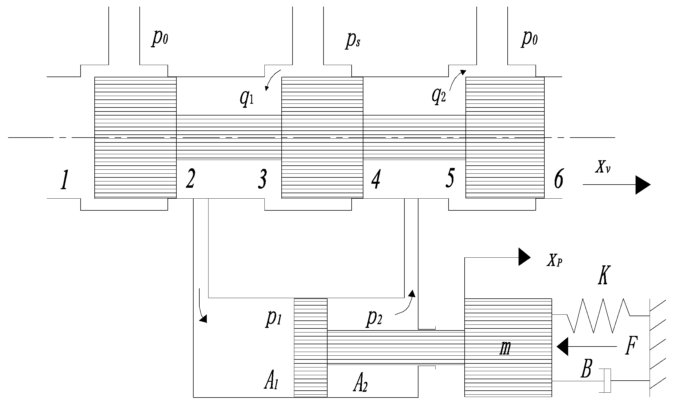
In the electro-hydraulic servo system, compared with the symmetrical hydraulic cylinder, the asymmetrical cylinder has the advantages of occupying a small space, being a simple structure and having a low cost, so it is widely used. In this paper, a four-way three-position (4/3) valve-controlled asymmetric hydraulic cylinder was used as the power mechanism of the electro-hydraulic servo system; the structure diagram of the valve-controlled asymmetric hydraulic cylinder is shown in Figure 1.
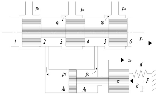
Figure 1.
Structure diagram of valve-controlled asymmetric hydraulic cylinder.
Let the positive direction of the displacement of the spool of the servo valve be the direction shown by the arrow in Figure 1, at time . Let the ratio of the effective area of the bore area to the rod area of the asymmetric cylinder be , where is the effective area of the bore, is the effective area of the rod.
When , the spool moves to the right, the piston rod extends, and the load pressure is
and the load flow is:
When, , the spool moves to the left, the piston rod retracts, the load pressure is
and the load flow is:
The flow continuity equation of the piston chamber of the valve-controlled asymmetric hydraulic cylinder is:
The flow continuity equation of the rod chamber of the valve-controlled asymmetric hydraulic cylinder is:
where is the effective volume of the piston-side chamber; is the effective volume of the rod-side chamber; is the effective bulk modulus of the hydraulic oil; is the internal leakage coefficient of the cylinder; is the external leakage coefficient of the cylinder; is the displacement of the piston; is the pressure of the piston-side chamber; and is the pressure of the rod-side chamber.
The positive direction of piston displacement is defined as the direction shown by the arrow in Figure 1, when the piston extends. Taking > 0 as an example, the flow equation of the four-way three-position (4/3) valve is established as
where is the flow coefficient of the valve; is the area gradient of the valve; and is the oil density. The flow rate of the piston-side chamber can be expressed by the product of the velocity of the piston and the effective area of the bore area. Similarly, the flow rate of the rod-side chamber can be expressed by the product of the velocity of the piston and the effective area of the rod area. Therefore, the relationship between the flow rate of the piston-side chamber and the flow rate of the rod-side chamber is
where is the velocity of the piston.
The pressure of the piston-side chamber can be expressed as
The pressure of the rod-side chamber can be expressed as
where is the system pressure.
Equations (1), (2) and (7)–(10) can be combined into the load flow equation:
where is a constant.
Linearizing Equation (7), we obtain
where is the flow gain of the valve and is the flow-pressure coefficient of the valve.
From Equations (1), (2), (5) and (6), the load flow is obtained as
where is the equivalent leakage coefficient of the cylinder; is the incidental leakage coefficient of the cylinder; and is the equivalent volume of the cylinder.
The resulting force equation between the hydraulic cylinder and the load is
where m is the equivalent load mass; B is the equivalent load damping; K is the equivalent load stiffness; and F is the equivalent load force.
Equations (5), (12) and (14) are the three basic equations and the displacement equation of the valve-controlled asymmetric hydraulic cylinder, Laplace transformed, can be obtained as
where is the total flow-pressure coefficient; is obtained by the Laplace transform of ; is the change in load flow caused only by the displacement of the spool; and is the Laplace transform of the supply pressure .
Supposing the spring stiffness is , the damping coefficient is usually much larger than , so that . Under Equation (15), it reduces to
where is the hydraulic natural frequency and is the damping ratio.
When , the same formula as Formula (16) can be deduced in the same way.
3. Design of Sliding Mode Controller Based on Adaptive Reaching Law
3.1. Design of Sliding Surface
The nonlinear effect of the servo valve is not considered in the electro-hydraulic servo system, and it is simplified as a proportional link, through the mathematical model of the electro-hydraulic servo system, the transfer function of the control voltage of the servo valve to the piston displacement of the hydraulic cylinder is obtained as
where is the system’s open-loop gain obtained by simplifying it into a proportional link without considering the nonlinear influence of the servo valve. Then, the state equation of the electro-hydraulic position servo system is as follows
In Equations (19)–(21), the controlled object is the third-order system, and is the system’s state variable. is the piston displacement of the cylinder; is the piston velocity of the cylinder; is the piston acceleration of the cylinder; is the system’s control input; and is the system’s output.
The state equation of the system model can be expressed as
The displacement tracking error of the system is
where is the desired motion trajectory.
The error vector of the system is defined as
The error state equation can be written according to Equations (22) and (23):
The designed sliding mode switching function is
The state equation of the sliding mode motion is
For satisfying , simplifying the state Equation (28) of the sliding mode motion yields
Equation (29) determines the dynamic quality of the sliding mode, and and are obtained by the pole configuration method.
3.2. Controller Design
Step 1: Designing a suitable controller can make the sliding points outside the sliding mode switching surface reach the sliding mode switching surface within a certain period of time, that is to say, the following conditional expression is satisfied
The equivalent control part can be derived from Equation (27) to obtain
From conditional Equation (30), the equivalent
control can be obtained as
Step 2: Design of the reaching law. For the traditional exponential reaching law which is commonly used,
where
Combining (31) and (33) we get
Substituting into (31) we get
The exponential reaching law SMC control law is designed as:
If is too small, the approach velocity will be very slow, and the adjustment process will be too slow; on the contrary, if is too large, the system velocity will be large, and the jitter will be large when the system reaches the switching surface.
A better adaptive reaching law for reducing system jitter is adopted below. The constructed adaptive reaching law is
Combining Equations (31) and (38), we obtain
Substituting into Equation (31) yields:
The SMC actual control law is designed as
where and are the adaptive reaching law parameters, and .
3.3. Characteristic Analysis of SMC Controller Based on Adaptive Reaching Law
When the system state variable is far away from the sliding mode surface, is the largest, , plays a major role in the controller output, and
ensuring that the rate of approaching the sliding mode surface is large enough.
When the system state variable moves in the direction close to the sliding mode surface, decreases, approaches zero, and plays a major role in the output of the controller:
where converges to near the origin and the approach velocity decreases with the decrease of .
Next, the characteristics of the SMC controller using the adaptive reaching law are analyzed and proved. Only when the reaching law meets the arrival condition can the existence of the sliding mode state be guaranteed, that is, it satisfies .
Theorem 1.
The adaptive reaching law has reachability.
Proof of Theorem 1.
Suppose a Lyapunov function , and derivate this function to obtain . From the adaptive approach rate parameter , we obtain , it can be seen that the system satisfies the arrival condition, that is, the adaptive reaching law satisfies the arrival condition. □
Theorem 2.
For the adaptive reaching law, the reaching law can make the system reach the sliding mode surface in a certain time, that is, the system converges toin a certain time.
Proof of Theorem 2.
Assuming the initial position , the proof of the arrival time of the system is divided into two stages. □
- Approach from the initial postion . At this stage , ignoring the term influence, that is , by integrating it, we obtainand as
- From , approach . At this stage , ignoring the shadowing of , that is, , by integrating it, we obtainand as
It can be obtained that the total time for the system state trajectory to reach the sliding surface is
Assuming that the second-stage system state lies between and , and the above derivation ignores secondary factors, then .
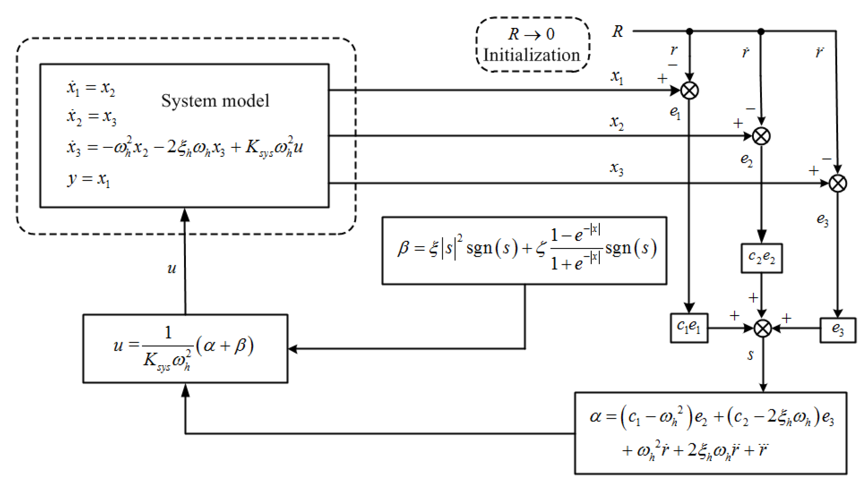
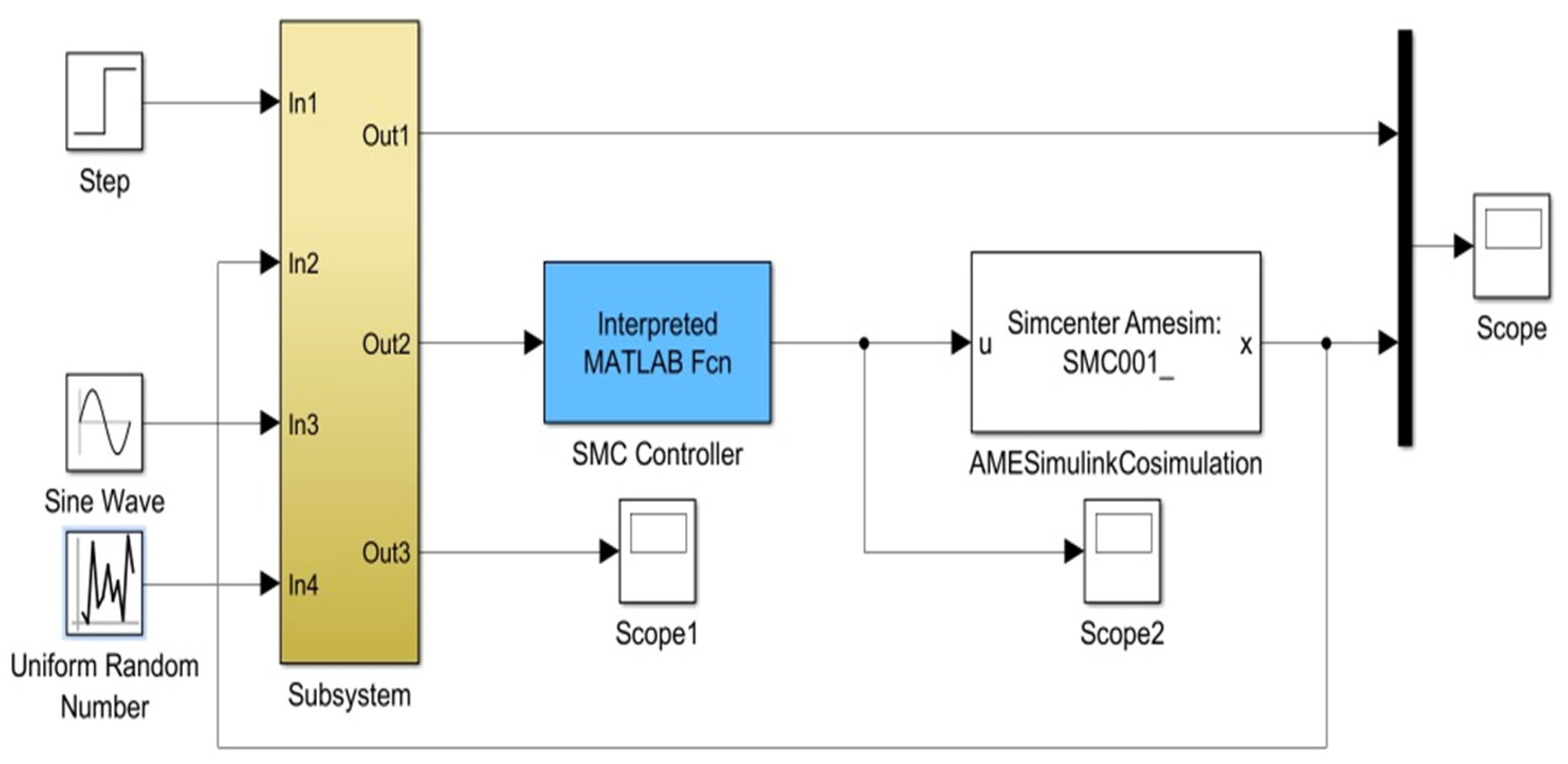
It can be seen that the electro-hydraulic position servo system designed in this paper can reach the sliding surface in a limited time. The schematic diagram of the SMC system based on the adaptive reaching law is shown in Figure 2. The AMESim/Simulink co-simulation block diagram is shown in Figure 3.
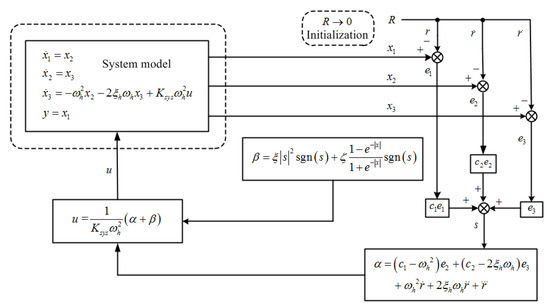
Figure 2.
Schematic diagram of SMC system based on adaptive reaching law.
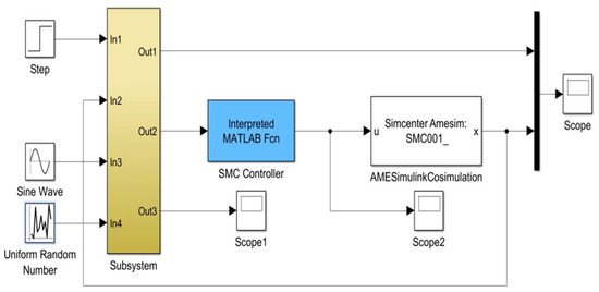
Figure 3.
AMESim/Simulink co-simulation block diagram.
4. Simulation Analyses
Some parameters of the electro-hydraulic position servo system studied in this paper are shown in Table 1, the parameters of the adaptive reaching law SMC algorithm are shown in Table 2, and the parameters of the exponential reaching law SMC algorithm are shown in Table 3. The nonlinear electro-hydraulic position servo system model was used with AMESim in the AMESim/Simulink co-simulation. The sampling time in the simulation was 0.001 s.

Table 1.
Parameters of electro-hydraulic position servo system.
Table 2.
Parameters of adaptive reaching law SMC algorithm.
Table 3.
Parameters of exponential reaching law SMC algorithm.
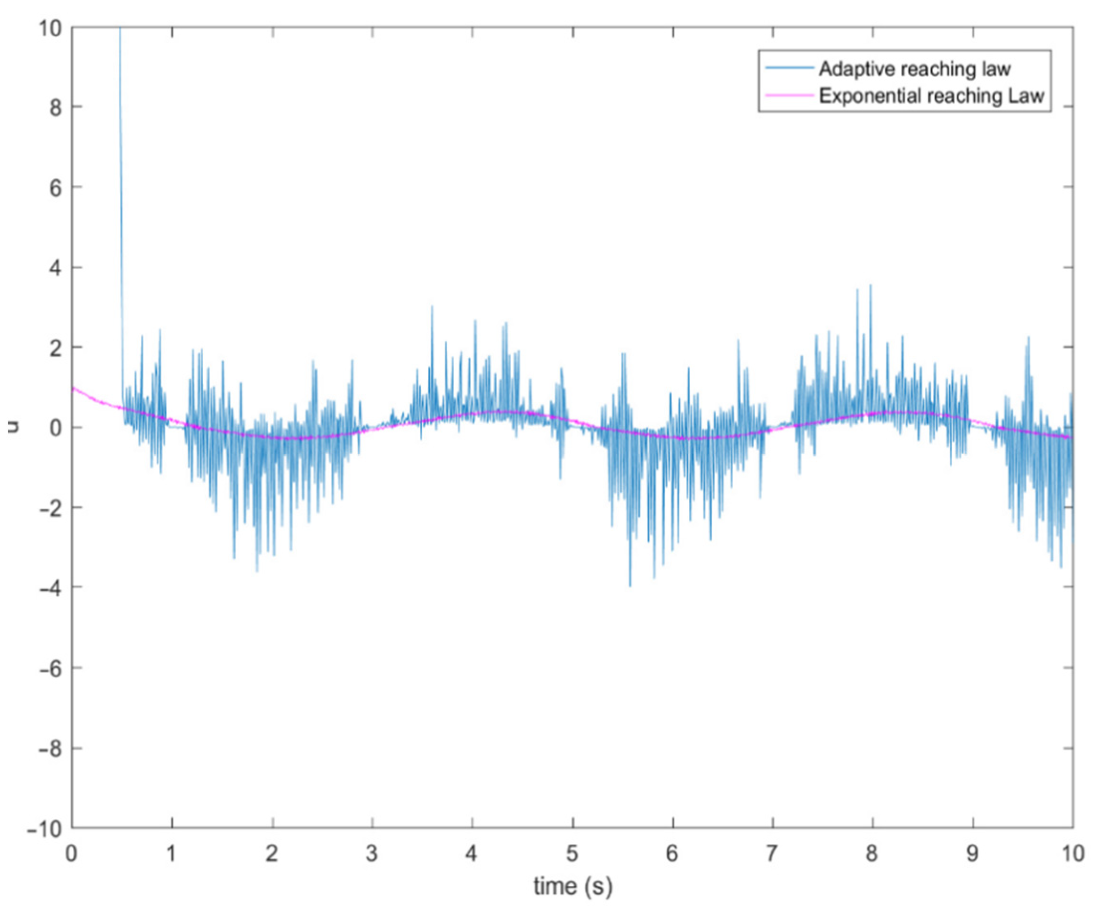
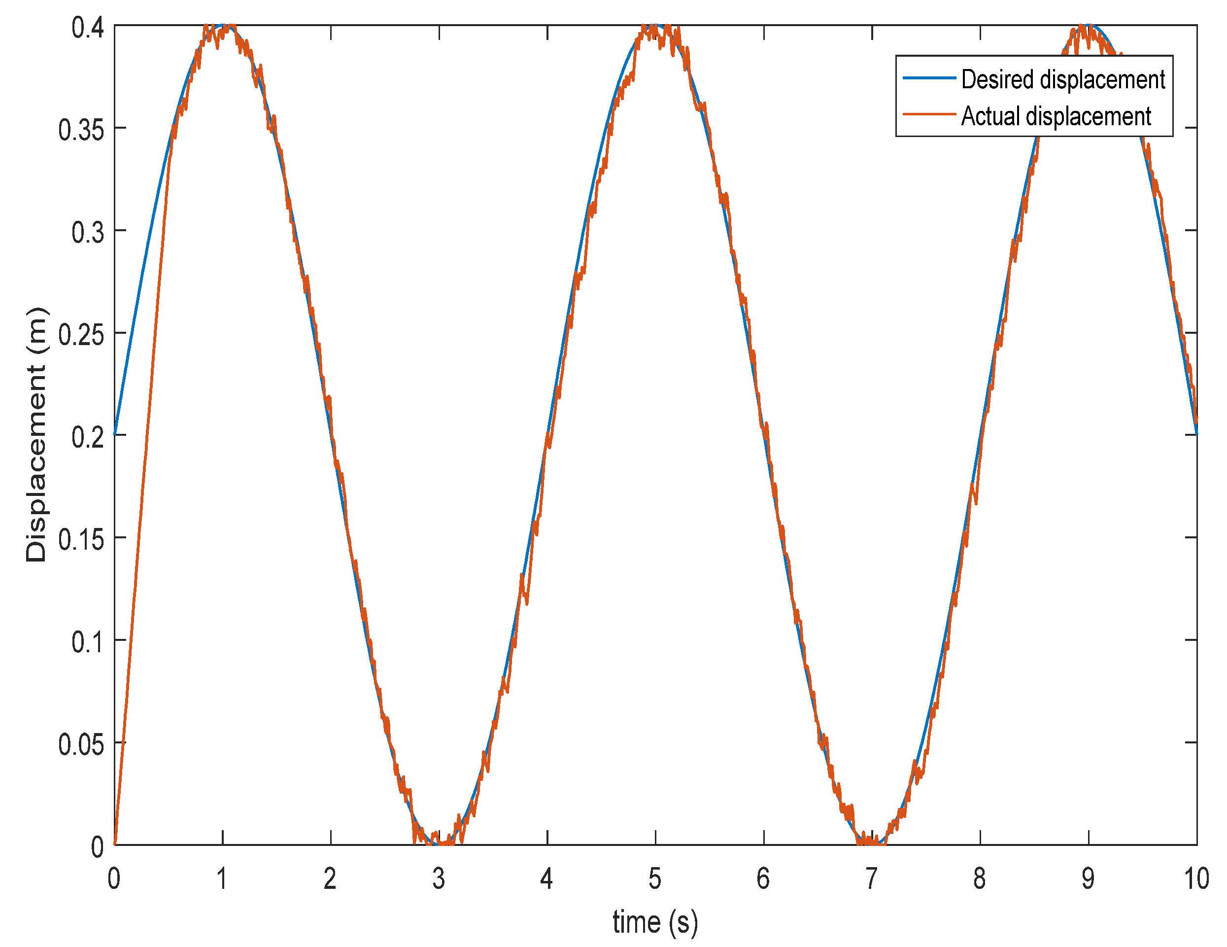
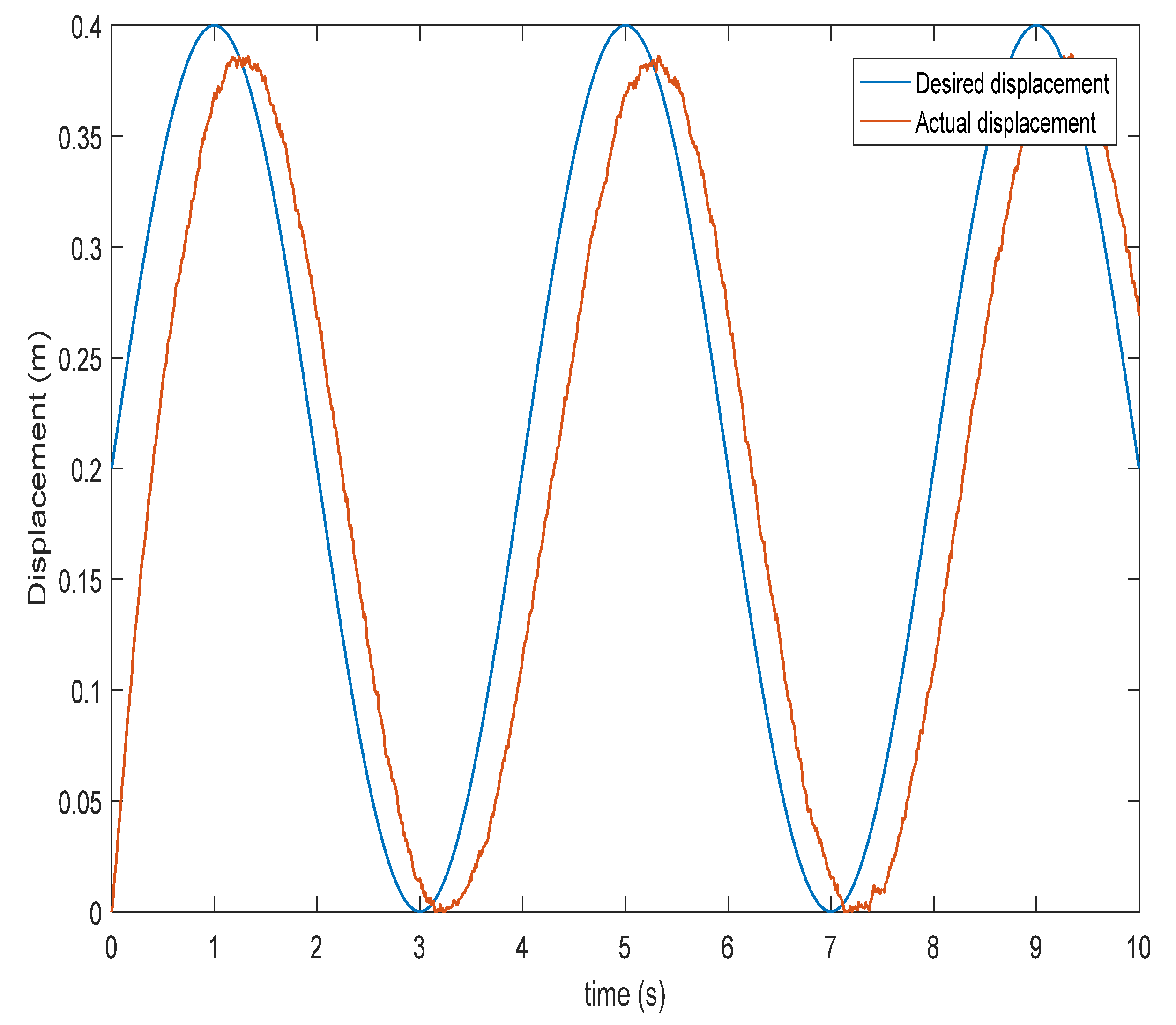
The paper uses the co-simulation function of AMESim and Simulink to simulate the system. Giving a sinusoidal signal, the SMC algorithm based on the exponential reaching law and the SMC algorithm based on the adaptive reaching law were used for the simulation and the obtained curves were compared and analyzed. Figure 4 is the tracking characteristic curve of the SMC system based on the exponential reaching law, and Figure 5 is the tracking characteristic curve of the SMC system based on the adaptive reaching law. Compared with the SMC algorithm based on the traditional exponential reaching law, the SMC algorithm of the adaptive reaching law has a great improvement in the control accuracy, and the following effect is obviously better than that of the SMC system using the traditional exponential reaching law algorithm. As shown in Figure 6, compared with the exponential reaching law SMC algorithm, the adaptive reaching law SMC algorithm can adaptively adjust the system control variables, so that the final displacement tracking effect is better.
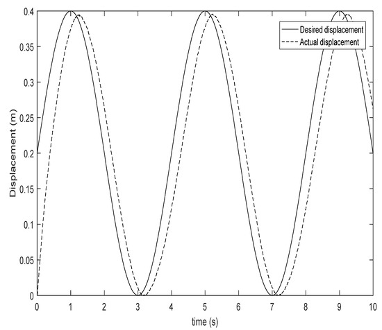
Figure 4.
Displacement tracking trajectory of SMC algorithm using exponential reaching law.
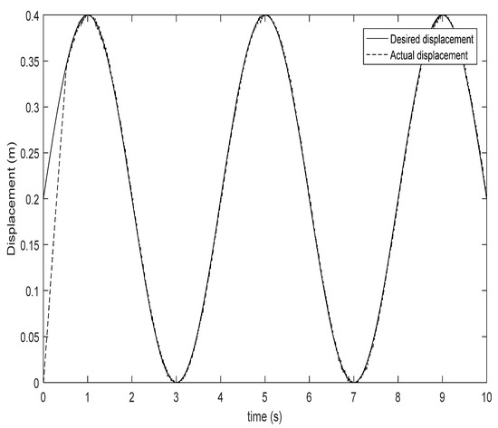
Figure 5.
Displacement tracking trajectory of SMC algorithm using adaptive reaching law.

Figure 6.
Curves of control variables under different reaching laws.
A bounded white noise interference signal was added to the given sinusoidal signal, and the exponential reaching law and the adaptive reaching law SMC controllers were used for the simulation, respectively. It can be seen from Figure 7 and Figure 8 that the displacement tracking effect of the adaptive reaching law SMC algorithm is obviously better than that of the exponential reaching law SMC algorithm, after being disturbed. The proposed adaptive reaching law SMC controller improves the robustness of the system.
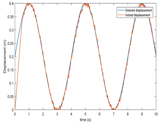
Figure 7.
Displacement tracking curve of adaptive reaching law SMC algorithm after disturbed signal.
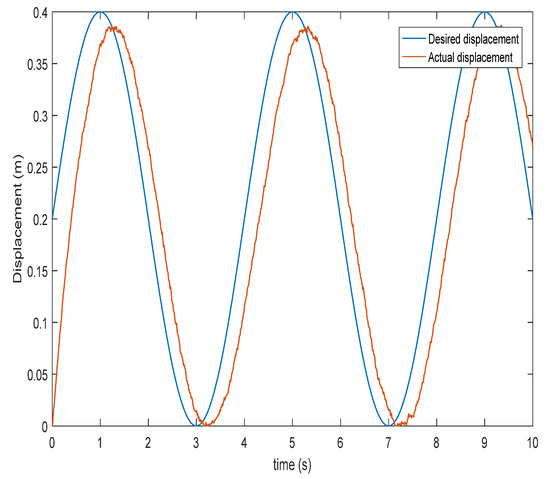
Figure 8.
Displacement tracking curve of exponential reaching law SMC algorithm after disturbed signal.
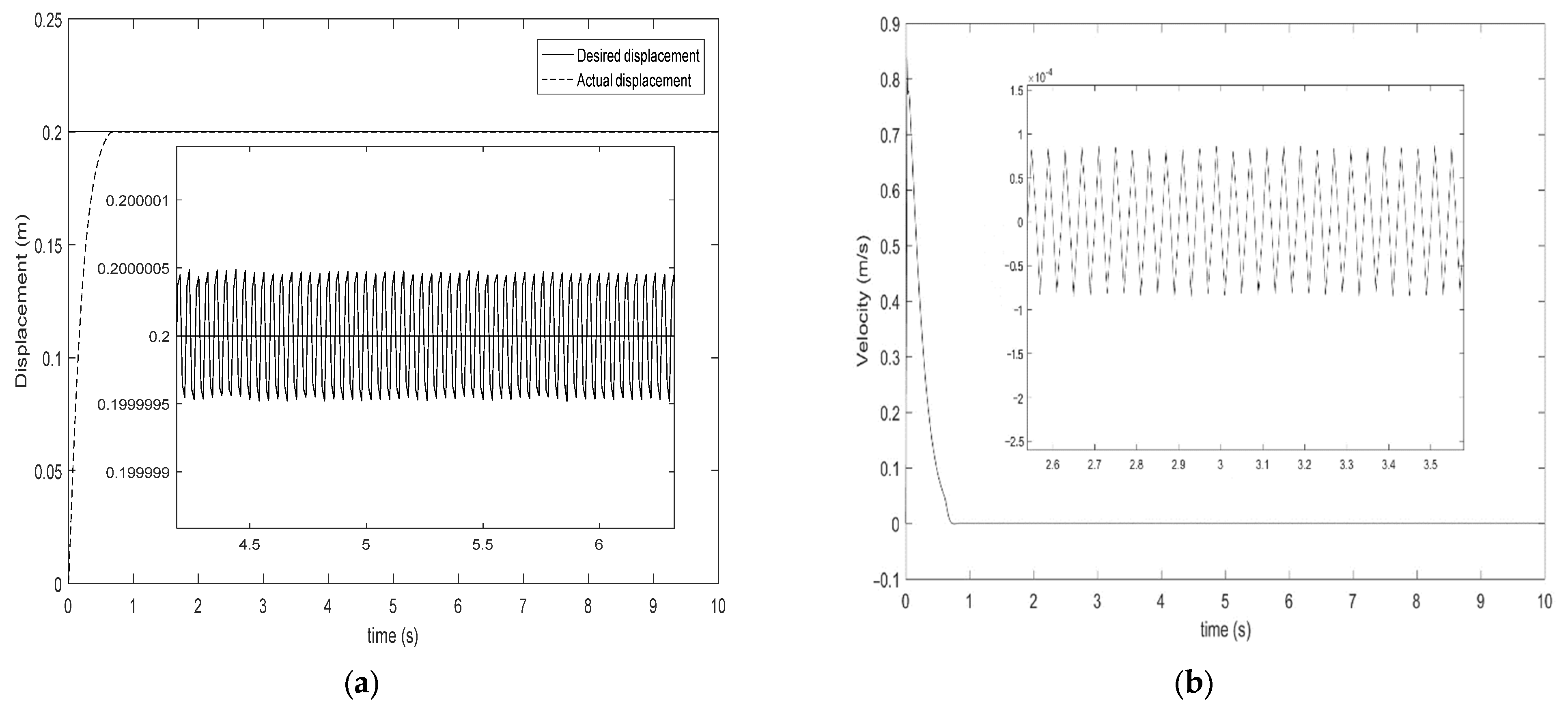
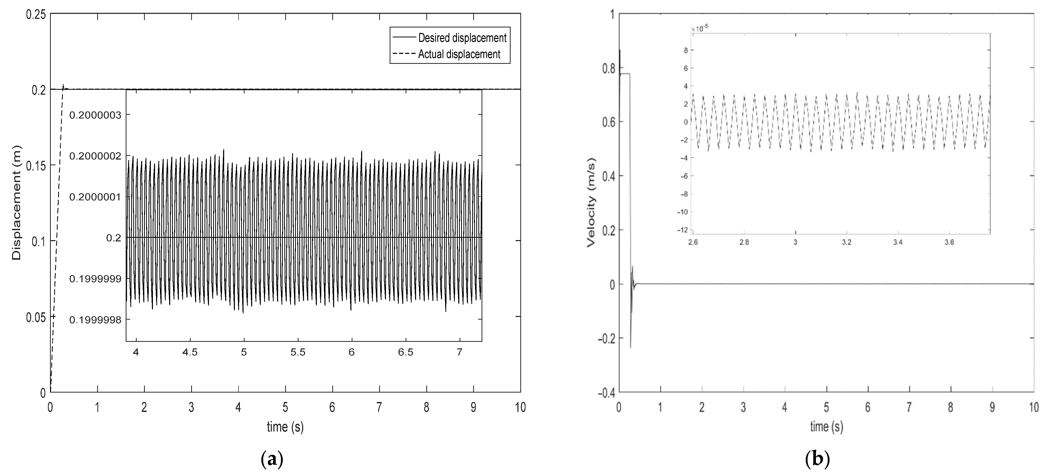
Giving a step signal, we used the SMC algorithm based on the exponential reaching law and the SMC algorithm based on the adaptive reaching law to simulate the piston displacement trajectory and piston velocity trajectory. It can be seen from Figure 9 that the SMC algorithm based on the exponential reaching law can make the piston reach a given position, but there is buffeting, the piston displacement buffeting range is ±0.0005 mm, and the piston velocity buffeting is ±0.0001 m/s. It can be seen from Figure 10 that the chattering range generated by the SMC algorithm based on the adaptive reaching law makes the piston reach the given position at ±0.0002 mm, compared with the SMC algorithm based on the exponential reaching law, where the chattering is only two-fifths of that when using the exponential reaching law, and the piston velocity buffeting is ±0.00003 m/s, only three-tenths of the velocity buffeting in Figure 9. The convergence velocity of the adaptive reaching law is faster than that of the traditional exponential reaching law. In addition, when the piston reaches the sliding mode surface, the buffeting of the system can be adaptively adjusted according to the system state variables, and finally converges to the equilibrium point of the electro-hydraulic position servo system. It can be seen that the SMC algorithm using the adaptive reaching law can obviously weaken the chattering problem caused by the SMC algorithm using the traditional exponential reaching law, the chattering of the piston displacement and velocity is obviously reduced, and the system still has a good tracking.
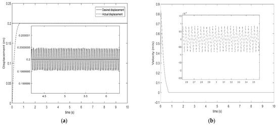
Figure 9.
Tracking trajectory of SMC algorithm using exponential reaching law. (a) Displacement buffeting curve and (b) velocity buffeting curve.

Figure 10.
Tracking trajectory of SMC algorithm using adaptive reaching law. (a) Displacement buffeting curve and (b) velocity buffeting curve.
5. Conclusions
In this paper, the dynamic models of the valve-controlled asymmetrical hydraulic cylinder were studied, and a simplified mathematical model of the electro-hydraulic position servo system was given by ignoring the nonlinear factors of the servo valve. The SMC method was studied in this paper. The SMC method based on the exponential reaching law is frequently used to control the displacement and velocity of the piston. However, this method leads to a large sliding mode chattering. Therefore, a novel SMC method based on the adaptive reaching law was designed in the paper. At the same time, a comparative analysis was conducted on the SMC controller using the traditional exponential reaching law and the adaptive reaching law. The simulation results showed that the method could effectively suppress the sliding mode chattering of the electro-hydraulic position servo system.
Author Contributions
Conceptualization, X.D.; Methodology, C.S.; Writing—original draft, C.S. and X.D.; Writing—review & editing, M.W. and J.L. All authors have read and agreed to the published version of the manuscript.
Funding
This work was supported by the Introduced Talents Foundation of Kunming University of Science and Technology (no. KKSY201901014).
Institutional Review Board Statement
Not applicable.
Informed Consent Statement
Not applicable.
Data Availability Statement
Applicable on request.
Conflicts of Interest
The authors declare that there is no potential conflict of interest.
References
- Li, Y.; He, L. Counterbalancing Speed Control for Hydrostatic Drive Heavy Vehicle Under Long Down-Slope. IEEE/ASME Trans. Mechatron. 2015, 20, 1533–1542. [Google Scholar] [CrossRef]
- Wang, C.; Jiao, Z.; Wu, S.; Shang, Y. Nonlinear adaptive torque control of electro-hydraulic load system with external active motion disturbance. Mechatronics 2014, 24, 32–40. [Google Scholar] [CrossRef]
- Wang, C.; Jiao, Z.; Quan, L. Nonlinear robust dual-loop control for electro-hydraulic load simulator. ISA Trans. 2015, 59, 280–289. [Google Scholar] [CrossRef] [PubMed]
- Pi, Y.; Wang, X. Trajectory tracking control of a 6-DOF hydraulic parallel robot manipulator with uncertain load disturbances. Control Eng. Pract. 2010, 19, 185–193. [Google Scholar] [CrossRef]
- Ma, Y.; Li, D.; Li, Y.; Yang, L. A Novel Discrete Compound Integral Terminal Sliding Mode Control with Disturbance Compensation for PMSM Speed System. IEEE/ASME Trans. Mechatron. 2022, 27, 549–560. [Google Scholar] [CrossRef]
- Ma, H.; Xiong, Z.; Li, Y.; Liu, Z. Sliding Mode Control for Uncertain Discrete-Time Systems Using an Adaptive Reaching Law. IEEE Trans. Circuits Syst. II Express Briefs 2021, 68, 722–726. [Google Scholar] [CrossRef]
- Ma, H.; Li, Y. A Novel Dead Zone Reaching Law of Discrete-Time Sliding Mode Control with Disturbance Compensation. IEEE Trans. Ind. Electron. 2020, 67, 4815–4825. [Google Scholar] [CrossRef]
- Ma, Z.; Liu, Z.; Huang, P. Fractional-Order Control for Uncertain Teleoperated Cyber-Physical System with Actuator Fault. IEEE/ASME Trans. Mechatron. 2021, 26, 2472–2482. [Google Scholar] [CrossRef]
- Utkin, V.I. Sliding Modes in Control and Optimization; Springer Science & Business Media: Berlin, Germany, 2013. [Google Scholar]
- Knohl, T. Sliding Mode Control in Electromechanical Systems. Utkin, J. Guldner, J. Shi, Taylor & Francis, London, 1999. Control Eng. Pract. 2000, 8, 1417–1418. [Google Scholar]
- Slotine, J.-J.E.; Li, W. Applied Nonlinear Control; Prentice Hall: Englewood Cliffs, NJ, USA, 1991; Volume 199. [Google Scholar]
- Levant, A. Universal single-input-single-output (SISO) sliding-mode controllers with finite-time convergence. IEEE Trans. Autom. Control 2001, 46, 1447–1451. [Google Scholar] [CrossRef] [Green Version]
- Laghrouche, S.; Plestan, F.; Glumineau, A. Higher order sliding mode control based on integral sliding mode. Automatica 2007, 43, 531–537. [Google Scholar] [CrossRef]
- Defoort, M.; Floquet, T.; Kokosy, A.; Perruquetti, W. A novel higher order sliding mode control scheme. Syst. Control Lett. 2009, 58, 102–108. [Google Scholar] [CrossRef] [Green Version]
- Tian, Q.-y.; Wei, J.-h.; Fang, J.-h.; Guo, K. Adaptive fuzzy integral sliding mode velocity control for the cutting system of a trench cutter. Front. Inf. Technol. Electron. Eng. 2016, 17, 55–66. [Google Scholar] [CrossRef]
- Lian, R. Adaptive Self-Organizing Fuzzy Sliding-Mode Radial Basis-Function Neural-Network Controller for Robotic Systems. IEEE Trans. Ind. Electron. 2014, 61, 1493–1503. [Google Scholar] [CrossRef]
- Sira-Ramirez, H. On the dynamical sliding mode control of nonlinear systems. Int. J. Control 1993, 57, 1039–1061. [Google Scholar] [CrossRef]
- Xue, L.; Zhiyong, G. Adaptive Sliding Mode Tracking Control for Nonholonomic Wheeled Mobile Robots with Finite Time Convergence. In Proceedings of the 36th China Control Conference, Dalian, China, 26–28 July 2017; pp. 721–726. [Google Scholar]
- Pandey, A.; Agrawal, R.; Mandloi, R.S.; Sarkar, B. Sliding mode control of dynamic voltage restorer by using a new adaptive reaching law. J. Inst. Eng. India Ser. B 2017, 98, 579–589. [Google Scholar] [CrossRef]
- Ma, Z.; Liu, Z.; Huang, P.; Kuang, Z. Adaptive Fractional-Order Sliding Mode Control for Admittance-Based Telerobotic System with Optimized Order and Force Estimation. IEEE Trans. Ind. Electron. 2022, 69, 5165–5174. [Google Scholar] [CrossRef]
- Liu, Y.; Wang, Z.; Xiong, L.; Wang, J.; Jiang, X.; Bai, G.; Li, R.; Liu, S. DFIG wind turbine sliding mode control with exponential reaching law under variable wind speed. Int. J. Electr. Power Energy Syst. 2018, 96, 253–260. [Google Scholar] [CrossRef]
- Yu, S.; Yu, X.; Shirinzadeh, B.; Man, Z. Continuous finite-time control for robotic manipulators with terminal sliding mode. Automatica 2005, 41, 1957–1964. [Google Scholar] [CrossRef]
- Zong, Q.; Zhao, Z.; Dou, L.; Sun, L. Integral sliding mode control for a class of nonlinear mismatched uncertain systems. In Proceedings of the 2008 2nd International Symposium on Systems and Control in Aerospace and Astronautics, Shenzhen, China, 10–12 December 2008; pp. 1–4. [Google Scholar]
- Pan, J.; Li, W.; Zhang, H. Control algorithms of magnetic suspension systems based on the improved double exponential reaching law of sliding mode control. Int. J. Control Autom. Syst. 2018, 16, 2878–2887. [Google Scholar] [CrossRef]
- Dong, H.; Yang, X.; Basin, M.V. Practical Tracking of Permanent Magnet Linear Motor Via Logarithmic Sliding Mode Control. IEEE/ASME Trans. Mechatron. 2022, 1–10. [Google Scholar] [CrossRef]
- Guo, K.; Wei, J.; Fang, J.; Feng, R.; Wang, X. Position tracking control of electro-hydraulic single-rod actuator based on an extended disturbance observer. Mechatronics 2015, 27, 47–56. [Google Scholar] [CrossRef]
- Wei, J.; Zhang, Q.; Li, M.; Shi, W. High-performance motion control of the hydraulic press based on an extended fuzzy disturbance observer. Proc. Inst. Mech. Eng. Part I J. Syst. Control Eng. 2016, 230, 1044–1061. [Google Scholar] [CrossRef]
- Li, M.; Shi, W.; Wei, J.; Fang, J.; Guo, K.; Zhang, Q. Parallel Velocity Control of an Electro-Hydraulic Actuator with Dual Disturbance Observers. IEEE Access 2019, 7, 56631–56641. [Google Scholar] [CrossRef]
- Guo, Q.; Yin, J.-m.; Yu, T.; Jiang, D. Coupled-disturbance-observer-based position tracking control for a cascade electro-hydraulic system. ISA Trans. 2017, 68, 367–380. [Google Scholar] [CrossRef] [PubMed]
- Won, D.; Kim, W.H.; Shin, D.; Chung, C.C. High-Gain Disturbance Observer-Based Backstepping Control with Output Tracking Error Constraint for Electro-Hydraulic Systems. IEEE Trans. Control Syst. Technol. 2015, 23, 787–795. [Google Scholar] [CrossRef]
- Wenzhuo, S.; Jianhua, W.; Jinhui, F. Desired Compensation Nonlinear Cascade Control of High-Response Proportional Solenoid Valve Based on Reduced-Order Extended State Observer. IEEE Access 2018, 6, 64503–64514. [Google Scholar]
- Yao, J.; Jiao, Z.; Ma, D. Extended-State-Observer-Based Output Feedback Nonlinear Robust Control of Hydraulic Systems with Backstepping. IEEE Trans. Ind. Electron. 2014, 61, 6285–6293. [Google Scholar] [CrossRef]
- Wenxiang, D.; Jianyong, Y. Extended-State-Observer-Based Adaptive Control of Electro-Hydraulic Servomechanisms without Velocity Measurement. IEEE/ASME Trans. Mechatron. 2019, 25, 1151–1161. [Google Scholar]
- Guo, K.; Wei, J.; Tian, Q. Nonlinear adaptive position tracking of an electro-hydraulic actuator. Proc. Inst. Mech. Eng. Part C J. Mech. Eng. Sci. 2015, 229, 3252–3265. [Google Scholar] [CrossRef]
- Jianyong, Y.; Wenxiang, D. Active Disturbance Rejection Adaptive Control of Hydraulic Servo Systems. IEEE Trans. Ind. Electron. 2017, 64, 8023–8032. [Google Scholar]
- Yao, Z.; Yao, J.; Yao, F.; Xu, Q.; Xu, M.; Deng, W. Model reference adaptive tracking control for hydraulic servo systems with nonlinear neural-networks. ISA Trans. 2020, 100, 396–404. [Google Scholar] [CrossRef] [PubMed]
- Helian, B.; Chen, Z.; Yao, B.; Lyu, L.; Li, C. Accurate Motion Control of a Direct-Drive Hydraulic System with an Adaptive Nonlinear Pump Flow Compensation. IEEE/ASME Trans. Mechatron. 2021, 26, 2593–2603. [Google Scholar] [CrossRef]


Publisher’s Note: MDPI stays neutral with regard to jurisdictional claims in published maps and institutional affiliations. |
© 2022 by the authors. Licensee MDPI, Basel, Switzerland. This article is an open access article distributed under the terms and conditions of the Creative Commons Attribution (CC BY) license (https://creativecommons.org/licenses/by/4.0/).