Article

Steady State and Transient Vibration Analysis of an Exponentially Graded Rotor Bearing System Having a Slant Crack

1
Department of Mechanical Engineering, Bennett University, Greater Noida 201310, India
2
Rolls-Royce Plc, Derby DE24 8BJ, UK
3
Department of Industrial Engineering, University of Salerno, 84084 Fisciano, SA, Italy
*
Author to whom correspondence should be addressed.
Appl. Sci. 2022, 12(14), 6900; https://doi.org/10.3390/app12146900
Submission received: 20 May 2022 / Revised: 23 June 2022 / Accepted: 5 July 2022 / Published: 7 July 2022

Abstract

:
The dynamic behaviour of a slant-cracked exponentially graded (EG) rotor-bearing system has been investigated using the finite element method for flexural vibrations. A two nodded EG rotor element has been developed based on the Timoshenko beam theory. Local flexibility coefficients (LFCs) of a slant-cracked EG shaft element have been derived using fracture mechanics concepts to develop the stiffness matrix of a cracked EG element. The steady-state and transient vibration responses of cracked and uncracked rotor systems have been simulated using the Houbolt time marching method. When a crack is present in the shaft, the subharmonic frequency peaks are centred on operating speed in the steady-state frequency responses, whereas on critical speed in the transient frequency responses at an interval frequency corresponding to the torsional frequency. It has been found that the crack parameters such as crack depth and location, temperature gradients and torsional frequencies have a significant influence on natural frequencies and dynamic responses, which could be implemented for efficient rotor crack detection methodologies.

1. Introduction

The evolution of the latest materials with enhanced structural performance has been a topic of interest for researchers and engineers in the last few decades. Laminated fibre reinforced polymers (FRPs) are substantially used in automobile, aerospace, marine, defence, and numerous other industries. However, laminated composites are prone to debonding, delamination and residual stress under high-temperature environments. Therefore, these drawbacks limit the performance of the laminated composites in thermo-elastic applications. Functionally graded material (FGM), a new class of composite, was developed in order to mitigate these limitations. The term FGM was coined by a group of Japanese scientists in 1984. Functionally graded materials (FGMs) are high performing advanced engineering materials that are microscopically inhomogeneous composites manufactured from two or more phases of constituents. FGMs are classified into metal–ceramic, ceramic–ceramic, metal–metal and ceramic–plastic. FGMs are multifunctional composites usually made of metal and ceramic constituents. Sturdy mechanical performance for the material is provided by the metallic component, whereas ceramic constituents offer corrosion resistance and thermal resistance.
The volume fractions of material constituents are varied along a particular direction based on different material gradation laws. Numerous modern fabricating techniques, such as chemical vapour deposition, centrifugal casting and spark plasma sintering, are discussed by few researchers to manufacture an FGM [1]. In the first place, FGMs were only manufactured for aircraft and spacecraft industries to sustain high temperatures since the temperature gradient of a 10 mm cross-section is estimated to reach as high as 1600 K [2], however, due to high material strength and better structural performance they are implemented in other mechanical industries.
Functionally graded (FG) structures were analysed by few researchers, excellent review papers were reported in the literature [3,4]. Simsek [5] performed the static analysis of an FG simply supported beam using the Ritz method based on higher-order shear deformation theory and Timoshenko beam theory. Aydogdu and Taskin [6] analysed the natural frequencies of the FG beam based on exponential and parabolic shear deformation beam theories. Nguyen et al. [7], based on the first-order shear deformation theory, investigated the static and free vibration of an axially loaded FG beam. Pradhan and Chakraverty [8] developed a computational model to investigate the free vibration of an FG Timoshenko and Euler beam for various boundary conditions using the Rayleigh–Ritz method. Fundamental frequencies of an FG beam were studied by Simsek [9] based on classical and different higher-order shear deformation beam theories. Azadi [10] analysed the fundamental frequencies of a hinged and clamped FG beam by employing the finite element method and modal analysis.
Rotor-bearing systems play a significant role in mining, marine, aerospace and automotive industries as the rotating shafts are one of the vital mechanical components in rotating machinery such as large turbine generators. Therefore, various researchers had investigated the vibration behaviour of the rotor system based on distinct models. Nelson and McVaugh [11] generalised Ruhl’s element by including the effects of gyroscopic moments and rotatory inertia. By including the transverse shear effects, Nelson [12] modelled a finite rotor element based on the Timoshenko beam theory. Few works were detailed on functionally graded rotor-bearing systems in the literature. Bose and Sathujoda [13] performed the free vibration analysis to investigate the natural frequencies of an FG rotor-bearing system using the three-dimensional finite element method. Since the FGMs can withstand high temperatures, the influence of temperature gradient on FG structures and rotating systems must be considered. Kiani and Eslami [14] performed the buckling analysis on FG beams under different types of thermal loading. Mahi et al. [15] investigated the free vibration frequencies of an FG beam for different material distributions (power-law, exponential-law and sigmoid-law) under a thermal environment based on a unified higher-order shear deformation theory. The effect of temperature gradients on fundamental frequencies of an FG rotor-bearing system based on the Timoshenko beam theory is investigated by Bose and Sathujoda [16].
Cracks are formed in the mechanical components of rotating machinery when they are subjected to excessive fatigue loads during the operation. Therefore, the dynamic response of the rotor systems had been analysed by several researchers. Dimarogonas [17] had observed that due to the presence of a crack, the local flexibility of the rotor is affected and developed an analytical formulation of local flexibility in relation to depth to investigate the dynamic response of the rotor under the influence of a crack. The flexural vibration behaviour of a transverse-cracked rotor-bearing system with multiple rotors is studied by Mayes and Davies [18]. Using the Paris’s equations, Dimarogonas and Papadopoulos [19] developed a local flexibility matrix for a cylindrical shaft having a crack. Papadopoulos [20] studied the torsional vibrations of a rotor having a transverse crack. Papadopoulos and Dimarogonas [21] developed a compliance matrix by coupling the bending and torsional vibration of a Timoshenko rotor with a transverse crack. Darpe et al. [22] computed the steady-state unbalance response of a cracked Jeffcott rotor system subjected to periodic axial impulses using the Runge–Kutta method. Ichimonji and Watanabe [23] analysed the transverse vibration of a slant cracked rotor system by considering the breathing effect of the crack. Dias-da-Costa et al. [24] presented a novel image deformation approach to monitor the propagation of the crack. Yao et al. [25] discussed the various characterised methods to detect the cracks. Sekhar and Prasad [26] formulated the local flexibility coefficients for a slant-cracked rotor element and studied the steady-state response of a rotor-bearing system having a slant crack using the finite element method. By using mechanical impedance, Sekhar et al. [27] detected and monitored the slant crack of the rotor system. Prabhakar et al. [28] used continuous wavelet transform to detect and monitor the cracks in rotors. Prabhakar et al. [29] studied the transient responses of a rotor system having a slant crack passing through the critical speeds by applying an unbalanced force and harmonically varying torque on the rotor.
While the above literature review divulges that the various researchers had been investigating the vibration response of cracked homogeneous rotors, analysis of the vibration behaviour of the cracked FG rotors is limited. Only a few works were reported on studying the dynamic response of the FG structures and rotors having defects in the literature. Dynamic analysis has been performed on porous and corroded FG rotor-bearing [30,31]. Gayen et al. [32,33] investigated the whirl and natural frequencies of a transverse cracked functionally graded rotor-bearing system. A slant crack might develop when an FG rotor is subjected to excessive torsional vibrations. Hence, it is significant to study the dynamic behaviour of an FG rotor-bearing system having a slant crack. Bose et al. [34] performed the whirl frequency analysis on an FG rotor-bearing system having a slant crack.
Although a few researchers performed the dynamic analysis to investigate the natural and whirl frequencies of the power-law based FG rotors with defects (porosity, corrosion, transverse crack and slant crack), detecting the presence of crack and its influence on the dynamic responses of an FG rotor have not been reported in the literature yet. To the best of the author’s knowledge, the steady-state and transient responses of an exponential-law based slant-cracked functionally graded rotor-bearing system to detect and understand the influence of the cracks have not been reported in the literature. Therefore, the principal aim of the present work is to study the natural frequencies, steady-state and transient time responses, and the corresponding frequency spectra of a slant cracked exponentially graded (EG) rotor-bearing system by considering the breathing effect of the slant crack.
The organisation of this current research work is as follows. Primarily, an FG rotor-bearing system having an exponentially graded shaft is considered in the present work. The material properties are graded along the radial direction of the FG shaft by using exponential law, whereas exponential temperature distribution (ETD) law is used to simulate the temperature gradients across the cross-section of the FG shaft. Although Sekhar and Prasad modelled a slant crack in a steel rotor-bearing system [26], the derivations and modelling of the slant-cracked EG rotor-bearing system are not available in the literature. Therefore, a two-nodded EG rotor element with and without a slant crack are formulated based on Timoshenko beam theory using the finite element method. Then, the stiffness matrix of a slant-cracked EG rotor element is developed by determining the local flexibility coefficients using Paris’s equations. Transient and steady state vibration responses of EG rotor system have been simulated by considering the breathing slant crack in order to develop a crack detection method through frequency response. Finally, the influence of the crack parameters and temperature gradient on natural frequencies are investigated, and the effect of the crack depth, torsional frequency and temperature gradient on steady-state and transient responses of a slant-cracked EG rotor system is also analysed.

2. Materials and Methods

Material properties of an FGM vary along a particular direction known as gradation direction. The radial direction is considered as gradation direction in the exponentially graded (EG) shafts with a circular cross-section. Therefore, material constituents of the shaft are distributed along the radial direction of the shaft. The EG shaft is composed of ceramic constituents on the outer layer of the shaft, and the metallic components are present in the inner core of the EG shaft. The outer ceramic layer is made of Zirconia (ZrO2), whereas the inner metallic core is composed of Stainless Steel (SS). The percentage of the ceramic constituents increases, and the rate of metal constituents decreases while moving across the cross-section from the inner core of the EG shaft. Therefore, the material properties such as Young’s modulus and Poisson’s ratio depends on the position of material constituents. The position of the material properties is determined by the Voigt model [35], which is a simple rule for mixtures of composites. The material properties of a specific layer P L is given as
P L = P m V m + P c V c
where V m and V c are volume fractions of metal and ceramic, respectively, whereas P m and P c are material properties of metal and ceramic, respectively. The sum of volume fractions of metal and ceramic is
V m + V c = 1
Since the material properties vary with the temperature, the temperature dependency of the material properties is achieved by using Equation (3) [36].
P T = P 0 P 1 T 1 + 1 + P 1 T + P 2 T 2 + P 3 T 3
T is the temperature in Kelvin. P 1 , P 0 , P 1 , P 2 and P 3 are the coefficients of the temperature, which are listed by Reddy and Chin [37]. Since the volume fractions of the material constituents are difficult to determine, the material gradation laws are used. Exponential law is employed in the present work, and its detailed explanation is presented in the following subsection.

2.1. Material Gradation Based on Exponential Law

Material gradation laws such as exponential law, power-law and sigmoid law are used to assign the material properties to an FG shaft. Exponential law is used in the present work as it has an easily estimated parameter (λ) and mathematically controllable. Based on exponential law, the material properties can be expressed as
P e r , T = P m e x p λ ( r R i )
λ = log e P c P m R o R i
P e r , T is the temperature and position dependent material property. R o and R i are the outer and inner radius of the FG shaft, respectively. In the present work, an EG shaft with an inner radius R i = 0 is considered as shown in Figure 1.

2.2. Exponential Temperature Distribution

Temperature is also assumed to vary across the cross-section of the EG shaft. Normally, 1D Fourier heat conduction equation is used to determine the temperature variation along the solid circular shaft whose inner and outer radius are R i and R o , respectively.
d d r r K t h d T d r = 0
K t h is the thermal conductivity. r is the radial distance. T m and T c are inner and outer temperatures of the shaft. Heat generation is not considered in the present work. For boundary conditions, T = T m   when   r = R i   and   T = T c   when   r = R o   .
T = T m + Δ T e c t 1 e c 1
where c = l n K c K m , Δ T = T m T c and t = r R i   R o R i . A python code has been developed to assign the material properties and distribute the temperature across the cross-section of the cracked EG shaft.

3. Formulation of a Slant Crack in the EG Rotor Element

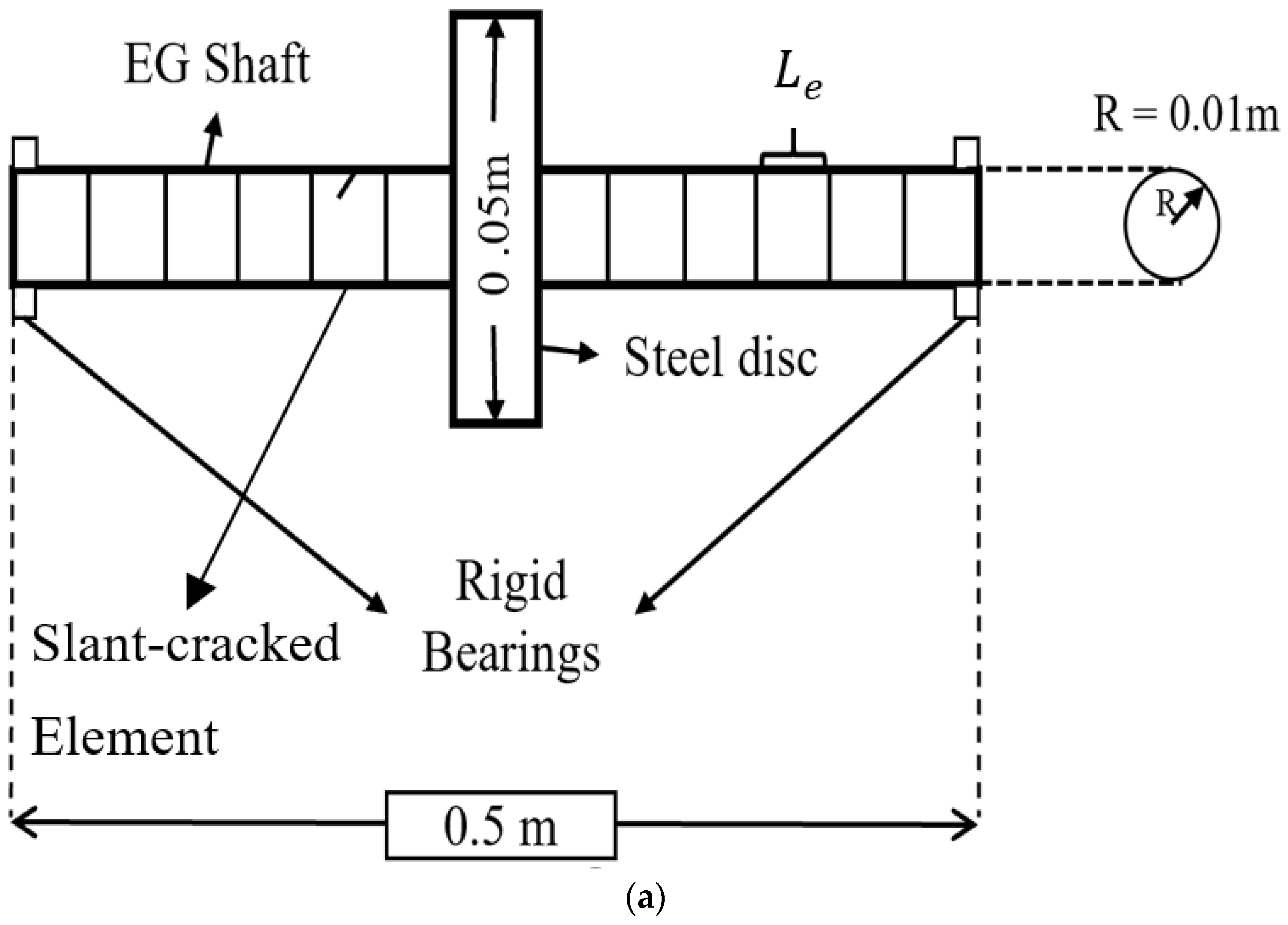
A slant-cracked EG Jeffcott rotor-bearing system used in the present work is shown in Figure 2a. The EG shaft is divided into twenty finite beam/rotor elements based on mesh convergence. A two-nodded EG shaft element is considered to have six degrees of freedom on each node; three translational degrees of freedom and three rotational degrees of freedom. A slant crack may propagate when a rotor is subjected to excessive torsional vibrations over a period of time [30]. The stiffness of cracked shaft element is affected, whereas the elemental stiffness matrix of other finite elements is regarded to remain the same under the specific restraint of element size [38]. The local flexibility coefficients of a slant cracked EG shaft element, which are expressed by the stress intensity factors, are derived in the following subsections.

3.1. Formulation of Flexibility Matrix of a Slant Cracked Element

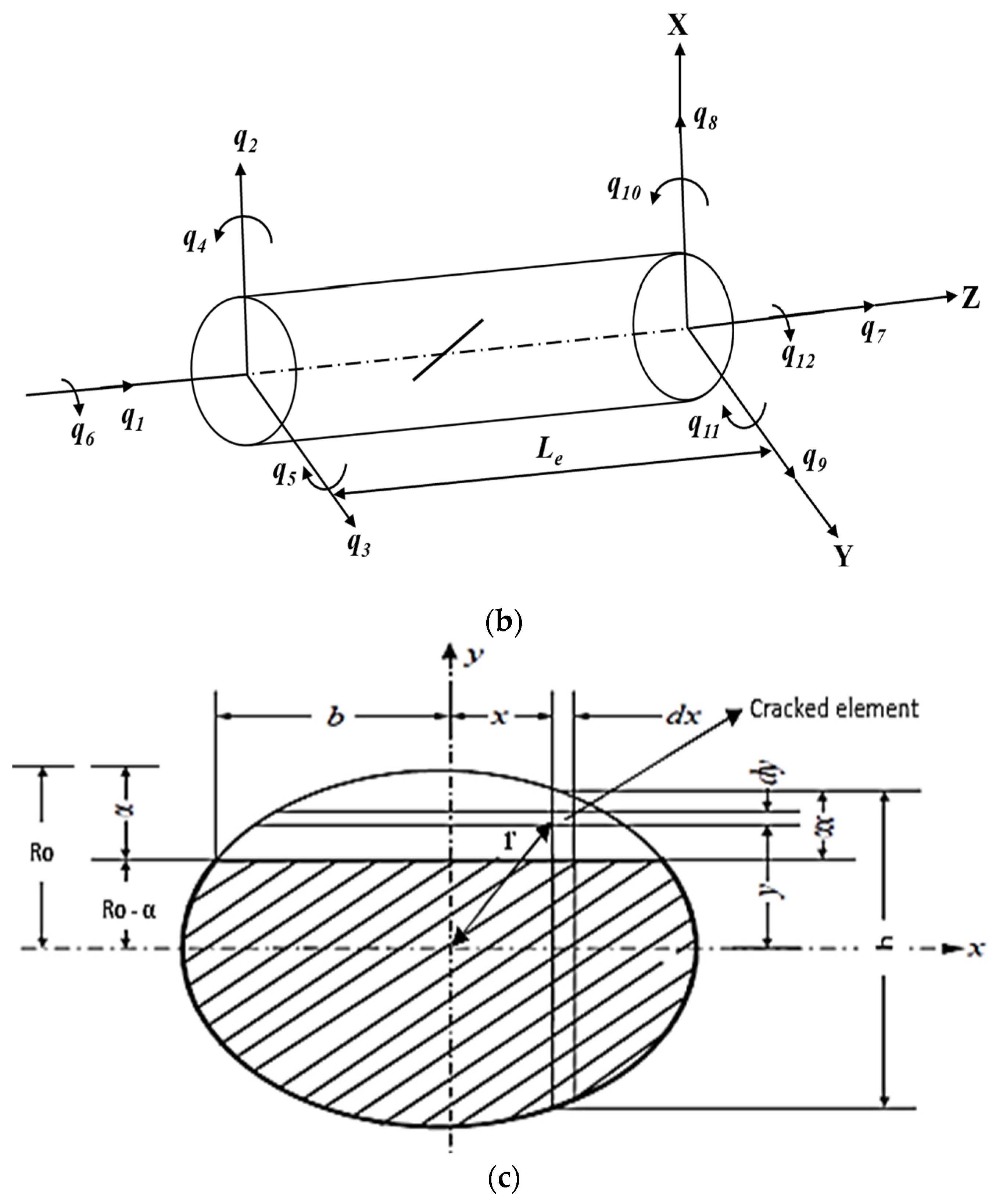
A finite slant-cracked EG shaft element has been developed in the present work. The cracked EG shaft element as shown in Figure 2b, is considered to have two nodes with six degrees of freedom on each node. The EG rotor element is subjected to an axial force (P1), shear forces (P2, P3), bending moments (P4, P5) and torsional moment (P6). Nodal vectors q are generated by these forces and moments, as shown in Figure 2b. The elliptical cut section view of the slant crack along the crack plane is shown in Figure 2c.
The geometry details of the slant crack are:
h = 2 R o 2 x 2 sin 2 45
b = R o 2 R o α   2   / sin 45
Since the cross-section along the slant crack is an ellipse, which is inclined at 45° to the shaft axis, the minor and major axis of the cross-section is R and R c o s 45 , respectively. The local flexibility coefficients (LFCs) of a slant cracked shaft element are derived using Castigliano’s theorem and Paris’s [39] equations are represented as the function of stress intensity factors. The additional displacement and energy equations are expressed as
u i = U c P i
U c = 0 α J s α d α
where J s α is strain energy density function (SDEF)
J s α = 1 E * j = 1 6 K I j 2 + j = 1 6 K I I j 2 + m j = 1 6 K I I I j 2
where E* = E, for plane stress condition, m = 1 + v. Stress Intensity Factors (SIFs), K i j ; where i = I, II, III modes and j = 1,2…,6, the load index.
K I 1 = σ I π α   F 1 α h K I 4 = σ 4 π α   F 1 α h   K I 5 = σ 5 π α   F 2 α h K I I 3 = σ 3 π α   F I I α h K I I 6 = σ 6 I I π α   F I I α h K I I I 2 = σ 2 π α   F I I I α h K I I I 6 = σ 6 I I I π α   F I I I α h K I 2 = K I 3 = K I 6 = K I I 1 = K I I 2 = K I I 4 = K I I 5 = K I I I 1 = K I I I 3 = K I I I 4 = K I I I 5 = 0 σ I = P 1 2 π R 2 ,   σ 4 = 2 P 4 x π R 4 ,   σ 5 = 2 P 5 2 R 2 x 2 π R 4 ,   σ 3 = k P 3 2 π R 2 ,   σ 6 I I = P 6 x 2 R 2 x 2 2   π R 4 ,   σ 2 = k P 2 2 π R 2 ,   σ 6 I I I = P 6 x 2 R 2 x 2   π R 4
where,
F 1 α h = tan λ λ 1 2 0.752 + 2.02 α h + 0.37 1 sin λ 3 cos λ
F 2 α h = tan λ λ 1 2 0.923 + 0.199 1 sin λ 4 cos λ
F I I α h = 1.122 0.561 α h + 0.085 α h 2 + 0.18 α h 3 1 α h 1 2
F I I α h = tan λ λ 1 2 ,   λ = π α 2 h
LFCs of a slant-cracked EG shaft element are computed by double integral as
C i j = 2 P i P j 0 b 0 α x J s y d y d x
where α x = R o 2 z   sin 45 °   2   R o α and b = R o 2 R o α   2   / sin 45 °
C c 11 = 2 π R o 4 0 b 0 α x y E e r , T F 1 2 α h d y d x
C c 14 = 4 π R o 6 0 b 0 α x y x E e r , T F 1 2 α h d y d x
C c 15 = 4 2 π R o 4 0 b 0 α x y R o 2 x 2 E e r , T F 1 α h F 2 α h d y d x
C c 22 = 2 π R o 4 0 b 0 α x y 1 + v e r , T k 2 E e r , T F I I I 2 α h d y d x
C c 33 = 2 π R o 4 0 b 0 α x y k 2 E e r , T F I I 2 α h d y d x
C c 44 = 8 2 π R o 8 0 b 0 α x y x 2 E e r , T F 1 2 α h d y d x
C c 45 = 8 2 π R o 8 0 b 0 α x y z R o 2 x 2 E e r , T F 1 α h F 2 α h d y d x
C c 55 = 16 2 π R o 8 0 b 0 α x y R o 2 x 2 E e r , T F 2 2 α h d y d x
C c 62 = 2 2 π R o 6 0 b 0 α x y 1 + v e r , T R o 2 x 2 E e r , T F I I I 2 α h d y d x
C c 63 = 2 π R o 6 0 b 0 α x k y z 1 + v e r , T E e r , T F I I 2 α h d y d x
C c 66 = 8 π R o 8 0 b 0 α x U 1 + m U 2 1 + v e r , T E e r , T d y d x
U 1 = 0.25 2 z 2 y F I I 2 α h ,   U 2 = 0.5 2 1 x 2 y F I I I 2 α h
E e r , T is Young’s modulus and Poisson’s ratio is v e r , T . The radial distance is transformed into r x , y = x 2 + y 2   to carry out the integration within the given limits. The flexibility matrix of the cracked EG shaft element is
C c = C c 11 0 0 C c 14 C c 15 0 0 C c 22 0 0 0 C c 62 0 0 C c 33 0 0 C c 63 C c 14 0 0 C c 44 C c 45 0 C c 15 0 0 C c 45 C c 55 0 0 C c 62 C c 63 0 0 C c 66

3.2. Stiffness Matrix of a Slant Cracked Element

The local flexibility coefficients of a shaft element without any crack are derived using the strain energy principle [34].
C u c = L e 6 0 R E e r , T   I r   d r [ 6 0 R E e r , T   I r   d r 0 R E e r , T A r 0 0 0 0 0   2 L e 2 0 0 3 L e 0     2 L e 2 3 L e 0 0         6 0 0   S y m     6 0           6   0 R E e r , T   I r   d r 0 R G e r , T   I r   d r ]
where L e is the length of a shaft element. Since the material is exponentially graded, E e r , T varies with radius and temperature based on exponential law. Therefore, E e r , T   I r   is integrated to assimilate the radial and temperature variation in Young’s modulus. Stiffness matrix of a cracked EG shaft element is obtained from the total flexibility matrix of a cracked EG shaft element. The total flexibility matrix of a slant cracked element is given as
C = C u c + C c
Three rotational and translational degrees of freedom are considered on each node, therefore, twelve degrees of freedom per each element. From the equilibrium condition
q 1 , q 2 , q 3   q 12   = T t r q 7 , q 8   q 12
where T t r is the transformation matrix, which is given as
T t r = 1 0 0 0 0 0 0 1 0 0 0 0 0 0 1 0 0 0 0 0 L e 1 0 0 0 L e 0 0 1 0 0 0 0 0 0 1 1 0 0 0 0 0 0 1 0 0 0 0 0 0 1 0 0 0 0 0 0 1 0 0 0 0 0 0 1 0 0 0 0 0 0 1
The stiffness matrix of the slant cracked shaft element is expressed as
K c = T t r C 1 T t r T

3.3. Modelling of Breathing Phenomenon

A slant crack opens due to tensional stresses on the surface of the crack generated by positive torsional moment, and negative torsional moment induces compressional stresses to close the crack. The breathing phenomenon of a slant crack tends to change the bending stiffness of the slant cracked EG shaft synchronously with the torsional vibration. The frequency of the torsional vibration is known as torsional frequency ω T . The variation in the stiffness of a slant cracked EG shaft due to breathing is expressed by a truncated cosine series as in Equation (29).
K = K ω T t = K 0 + K 1 cos ω T t + K 2 cos 2 ω T t + K 3 cos 3 ω T t
where t is time and K n ,   n = 0 ,   1 ,   2 ,   3 are the fitting coefficient matrices determined from the known behaviour of the stiffness matrices at specific angular locations. However, fully closed or open conditions of the crack are considered in the present work. The EG shaft element is treated as uncracked in fully closed condition. The conditions used for breathing of the crack are:
At   ω T t = 0 ,   K = K u c   and   2 Φ 2 K = 0
At   ω T t = π ,   K = K o p   and   2 Φ 2 K = 0
where Φ = ω T t , and op and uc stands for open and closed crack conditions, respectively.
K 0 = ( K o p + K u c ) / 2 ,   K 1 = 9 ( K u c K o p ) / 16
K 2 = 0 ,   K 3 = ( K o p K u c ) / 16
where K u c and K o p are the stiffness matrices of an EG shaft element with a closed and open crack, respectively. Thus, by using Equation (29), the stiffness of an EG cracked element at any time can be obtained for a given frequency of torsional vibration.

4. Finite Element Modelling of an EG Rotor-Bearing System

A two nodded uncracked EG shaft element has been developed based on the Timoshenko beam theory by contemplating the effects of gyroscopic moments, translational inertia, rotational inertia and transverse shear deformations. The elemental mass matrices, stiffness matrices and gyroscopic matrices of uncracked EG shaft elements are given in the present section. The equation of motion of a complete EG rotor-bearing system has been developed by including the slant crack model for determining the natural frequencies, and dynamic responses of a cracked and uncracked EG rotor-bearing system.

4.1. Finite EG Shaft Element without Crack

The equation of motion of an EG shaft element, expressed in Equation (32), can be derived by the application of Hamilton’s extended principle along with the equations of energy and the work functions [11,12].
M e + N e q ¨ Ω G e q ˙ + K e q = Q e
where M e , N e , G e and K e are elemental translational mass matrix, rotational mass matrix, gyroscopic matrix, and stiffness matrix, respectively. Q e is the excitation vector on the element and q is nodal displacement vector. Ω is the rotor speed of the shaft in rad/s. The spatial constraint matrices, which are used to derive the elemental mass, stiffness and gyroscopic matrices are analogous to the spatial constraint matrices used in [11].
The elemental translational mass matrix is expressed as
M e = 0 L e m ψ T ψ d s m = R i   R o 2 π ρ r r 3 d r
The elemental rotational mass matrix is expressed as
N e = 0 L e I D φ T φ d s I D = R i   R o π ρ r r 3 d r
The elemental stiffness matrix is expressed as
K e = 0 L e E I ¯ ψ T ψ d y d s + 0 L e κ G A ¯ ψ T ψ d y d s E I ¯ = R i   R o 2 π E e r , T r 3 d r κ G A ¯ = R i   R o 2 π r κ e r , T G e r ,   T d r
The elemental gyroscopic matrix is expressed as
G e = H e H e T H e = 0 L e I P φ w T φ v d s I p = R i   R o 2 π ρ r r 3 d r
where E e r ,   T is Young’s modulus, G e r ,   T is the modulus of rigidity, ν e r ,   T is Poisson’s ratio, κ e r ,   T is the shear form factor, ρ r is density, m is mass per unit length, R i is the inner radius of the EG shaft.   R o is the outer radius of the EG shaft, L e is the length of the element, I D diametric moment of inertia per unit length, I P is the polar moment of inertia per unit length, A is the area of cross-section, and I is the area moment of inertia. ψ and φ are the spatial constraint matrices associated with the translational and rotational shape functions, respectively. The equation of motion of a uniform disc and isotropic bearings are taken from the literature [17]. The uniform steel disc is located at the mid-span of the EG shaft. The ends of the EG shaft are supported by the linear isotropic bearings. The stiffness of bearings is considered as 1010 N/m. Bearings are rigid with high stiffness. The rotor-bearing data is presented in Section 7.

4.2. Global Equation of Motion and Solution Procedure to Compute Eigenfrequencies

The element matrices of a cracked and uncracked EG rotor, steel disc and linear isotropic bearings are assembled to form the global equation of motion of a cracked and uncracked EG rotor-bearing system.
M q ¨ + C Ω G q ˙ + K q = Q
where Q is the global excitation vector, q is the nodal displacement vector, G is the global gyroscopic matrix, M is the global mass matrix, K is the global stiffness matrix, C is the global damping matrix, Ω is the rotor speed of the system. Natural frequencies of an EG rotor-bearing system with and without crack are determined by representing Equation (37) as
A p ˙ + B p = 0
A = 0 M M Ω G ,   B = M 0 0 K ,   p = q ˙ q
The solution for Equation (38) can be assumed as
p = p o e λ t
On substituting Equation (39) in Equation (38), the eigenvalue problem is can be expressed as
B 1 A + λ I p o = 0
The eigenvalues are of the form
λ n Ω = ξ n Ω   ±   i ω n Ω
The inverse of the imaginary part gives the whirl frequency, and at Ω = 0, the inverse of the imaginary part gives natural frequency in r a d s .

5. Dynamic Response

The dynamic analysis of a cracked and uncracked EG rotor-bearing systems have been carried out using the steady-state and transient time and frequency responses. The responses of an EG rotor-bearing system are simulated using the Houbolt time marching scheme when the rotor is subjected to unbalanced excitation forces exerted by the disc due to its unbalance eccentricity ( e ). The unbalanced forces of disc mass ( M d ) acting on the mid-span of the EG shaft in x and y directions at an angular position ( θ ) can be written as
F d x = M d e θ ˙ 2 cos θ + θ ¨ sin θ
F d y = M d e θ ˙ 2 sin θ θ ¨ cos θ
In steady-state analysis, the angular position of the EG rotor is θ = Ω t , whereas the angular acceleration of the EG rotor is θ ¨ = 0 . Therefore, the EG rotor rotates with a constant angular speed, θ ˙ = Ω . However, in the transient analysis, the angular position of the rotor is expressed as θ = Ω 0 t + 1 2 α a c c t 2 as the angular speed of the EG rotor varies with time θ ˙ = Ω 0 + α a c c t . Therefore, the angular acceleration of the EG rotor is θ ¨ = α a c c . Ω 0 is the initial angular speed of the rotor, and t is time.

6. Validations

An FE code has been developed using Python to compute natural frequencies, steady-state and transient state responses of a cracked and uncracked exponentially graded rotor-bearing system. The developed FE code is validated with the published results to ensure the correctness of the code. A step-by-step validation of code is discussed in the following subsections.

6.1. Non-Dimensional Natural Frequencies of an Exponentially Graded Beam

Since the data on the EG rotor-bearing system is unavailable in the literature, non-dimensional natural frequencies ( ω ¯ = ω ( L / h ) ρ m h 2 / E m ) of an exponentially graded simply supported beam are computed using the developed Python code to substantiate the exponential material gradation, and temperature distribution as well as the mass and stiffness matrices used in the present work. The top and bottom layers of the EG beam are made of Stainless Steel (SS), and the centre layer is wholly composed of Alumina (Al2O3), as shown in Figure 3. The width of the beam is taken as 0.0254 m. The temperature of the middle surface is assumed at 293 K, whereas the temperature at top and bottom surfaces is considered at 393 K. The non-dimensional fundamental frequencies of an EG beam are calculated for two different slenderness ratios and tabulated in Table 1. Since the percentage of the error is minute, the computed values are in good accordance with the literature [15]. Therefore, it is confirmed that the material modelling, temperature distribution, mass and resulting stiffness matrices used to determine natural frequencies are precise. ρ m is the density of Stainless Steel, E m is the Young’s modulus of Stainless Steel and h is the thickness of the EG beam.

6.2. Normalised Natural Frequencies of a Slant-Cracked Steel Rotor-Bearing System

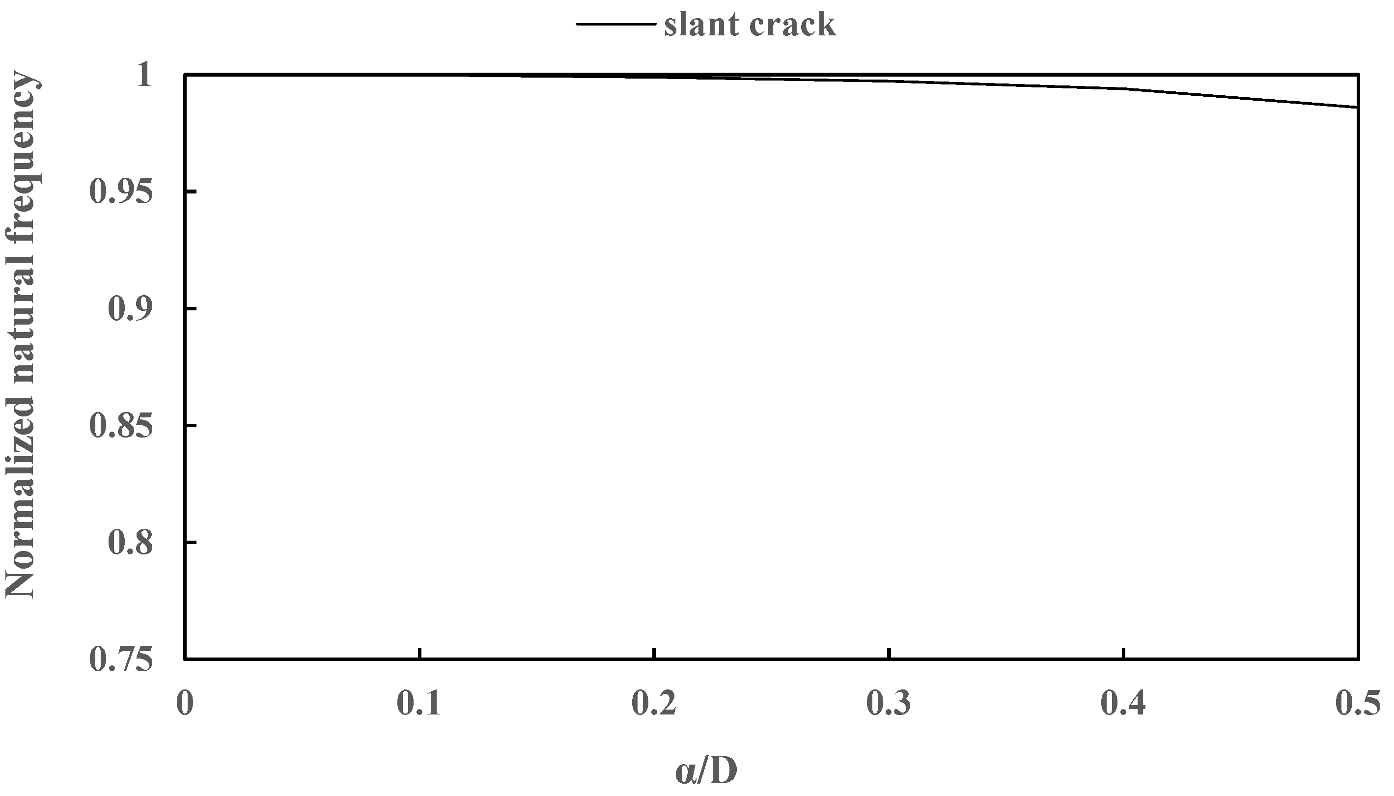
Since there are no works reported on slant-cracked EG rotor-bearing system, normalised natural frequencies (natural frequency of cracked rotor system/natural frequency of uncracked rotor system) of a steel rotor with an open slant crack have been validated to verify the slant crack formulation of the present work. The length and diameter of the rotor are 0.5 m and 0.02 m, respectively. A uniform steel disc is mounted at the mid-span of the rotor, which is supported by the bearings of the stiffness 105 N/m. The elastic modulus and density of the steel rotor are 208 GPa and 7800 kg/m3, respectively. The mass of the steel disc is 5.5 kg. The slant crack is located at a distance of 0.2 m from one of the bearings. The first natural frequencies of a slant-cracked rotor are computed and divided by the first natural frequency of a steel rotor to obtain the normalised natural frequencies. The normalised natural frequencies are plotted against normalised crack depth ( α ¯ = α / D ) as shown in Figure 4. Due to the unavailability of the data points of the graph in the literature [26], the digitising software has been used to obtain the data points of the graphs. The digitised values are tabulated in Table 2 and compared with the computed values of the present work. Since the difference between the computed values of the present work and digitised values is negligible, it can be confirmed that the slant crack model used in the present work is precise.

6.3. Dynamic Response of a Steel Rotor with a Breathing Crack

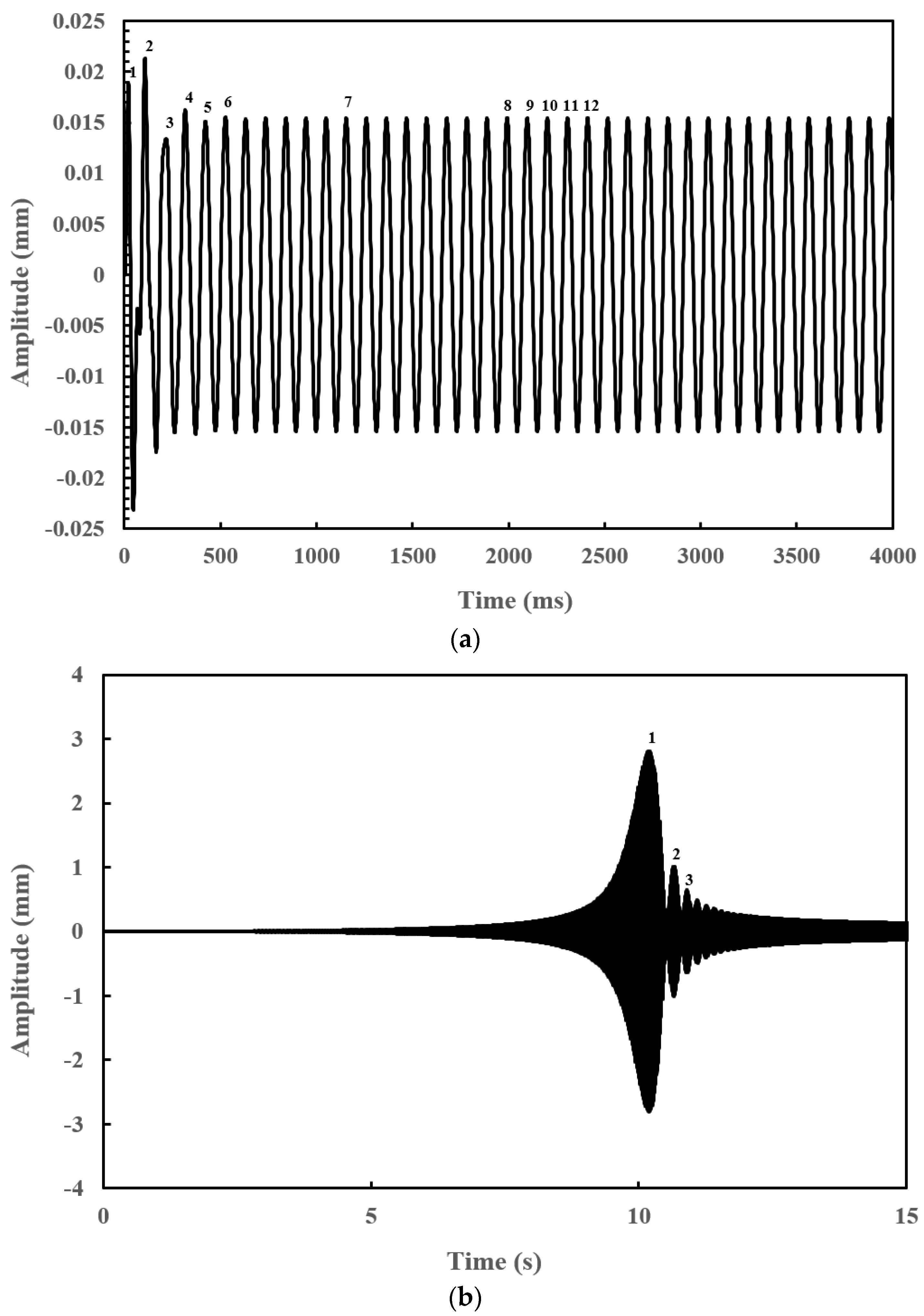
Steady-state and transient response of a steel rotor-bearing system with a slant crack is computed to validate the Houbolt method used in the present work. The rotor data from the previous subsection is taken for validating the steady-state response, whereas, for the transient response, the length and diameter of the rotor are considered to be the same. The rotor is discretised into ten elements, a disc is located at the centre and the ends of the rotor are supported by the bearings whose stiffness is 1010 N/m. Since the data points of the steady-state and transient responses are not available in the literature [26,29], digitisation software is used to obtain the data points. The corresponding points of the literature in Figure 5a,b are digitised and compared with the computed values of the present work in Table 3 and Table 4. As the difference between digitised data points of the literature [26,29] and the present work is minute, it can be concluded that Figure 5a,b are in good agreement with the literature.

7. Results and Discussions

In the present work, the natural frequencies of the slant-cracked EG rotor system are calculated to understand how the crack parameters and temperature gradients affect the dynamic behaviour of the EG rotor-bearing system. The steady-state and transient responses have been simulated to establish the slant crack detection methodology and to study the severity of the crack and the crack breathing frequency through the vibration responses of a slant-cracked EG rotor-bearing system. A Python code has been developed to determine the natural frequencies, steady-state and transient responses. The numerical results obtained in this section are based on the theory derived in this study with proper validations.
An EG rotor-bearing system with a slant crack is considered. The inner core of the EG shaft is made of Stainless Steel, and the outer layer is made of Zirconia. The material gradation and temperature distribution varied radially across the cross-section using exponential law and ETD. Natural frequencies, steady-state responses and transient responses have been calculated using finite element analysis for flexural vibrations. Houbolt time marching technique has been employed to compute the time response, and the corresponding frequency spectra are obtained by using Fast Fourier Transform. Rotor-bearing data used in the present work are tabulated in Table 5. Natural frequencies of an uncracked and cracked EG rotor-bearing system are computed at 10, 14, 18, 20 and 22 finite elements in Table 6 to check the mesh convergence. The natural frequencies are found to be converged when the EG rotor is discretised into twenty finite rotor elements. Therefore, twenty finite elements have been considered in the present work.

7.1. Effect of Crack Depth ( α ¯ ) on Natural Frequencies for Different Crack Locations ( L c ¯ )

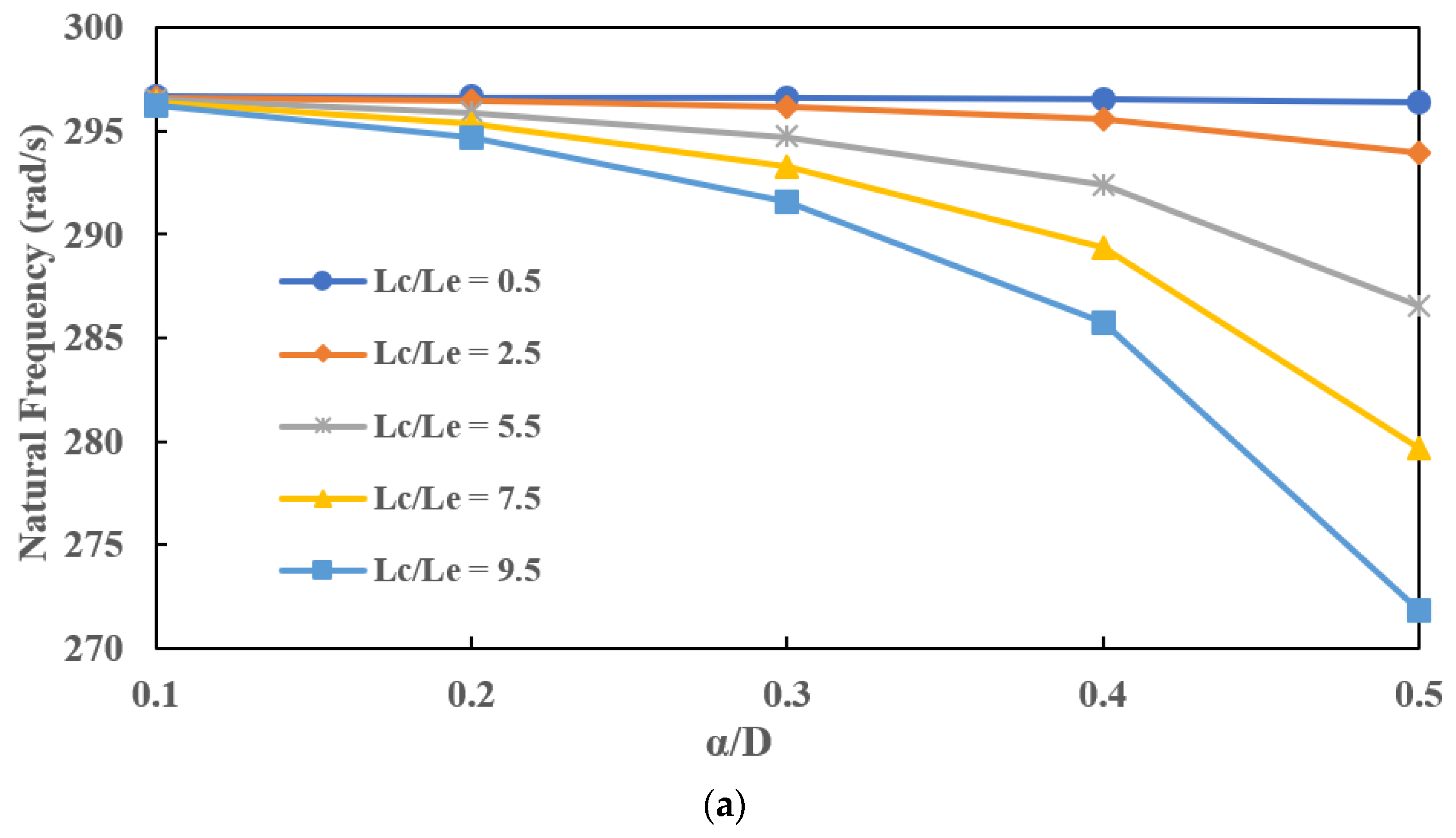
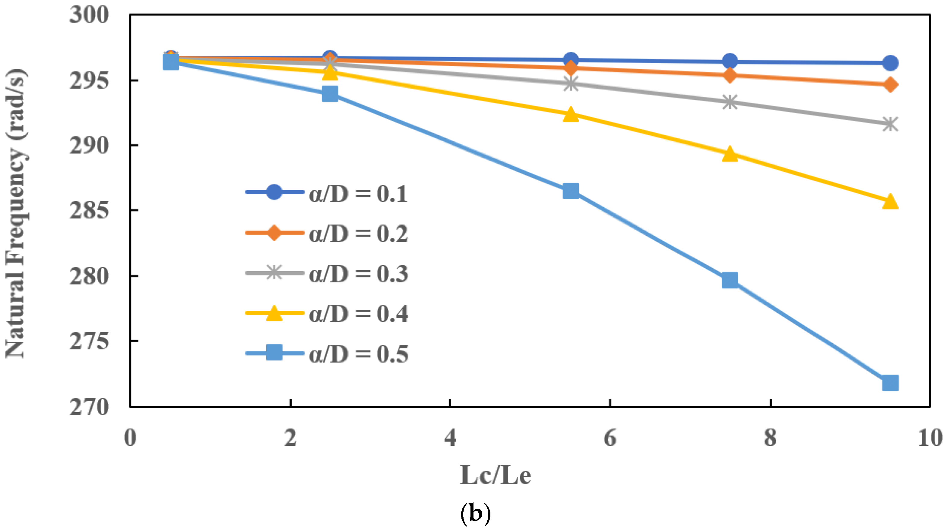
The natural frequencies of a slant-cracked EG rotor-bearing system at room temperature are plotted against normalised crack depths for different crack locations. It has been noted from Figure 6a, the natural frequencies of the rotor-bearing system decrease with an increase in crack depth. This phenomenon is caused due to the reduction in stiffness in the EG shaft with the increase in the crack depth. Natural frequencies of the slant-cracked EG rotor-bearing system, in Figure 6b, with the crack positioned near the bearings ( L c ¯ = 0.5) turn out to be higher than those obtained when the crack position is far from bearings (near the disc) ( L c ¯ = 9.5). The reason is that the crack effect is not significant when it is near to the mode’s nodal point, namely the bearing location. From Figure 6a, it is observed that the curve ( L c ¯ = 0.5) almost remains straight with the increase in crack depth.

7.2. Effect of Temperature Gradients (ΔT) on Natural Frequencies for Different Crack Depths

Natural frequencies of a slant-cracked EG rotor-bearing system have been computed for different thermal gradients at a normalised crack position, L c ¯ = 9.5. Here, the temperature of Stainless Steel (Tm) is fixed at 300 K, and the temperature of ZrO2 is varied accordingly. It can be noticed from Figure 7 that the natural frequencies of the system tend to decrease with an increase in temperature gradient, while the material properties, such as Young’s modulus, decrease with an increase in temperature. Therefore, the stiffness of the EG shaft is reduced. The presence of slant crack in the EG shaft further affects the stiffness of the EG rotor-bearing system. Consequently, the natural frequencies of the system are decreased.

7.3. Steady-State Responses of a Slant-Cracked EG Rotor-Bearing System

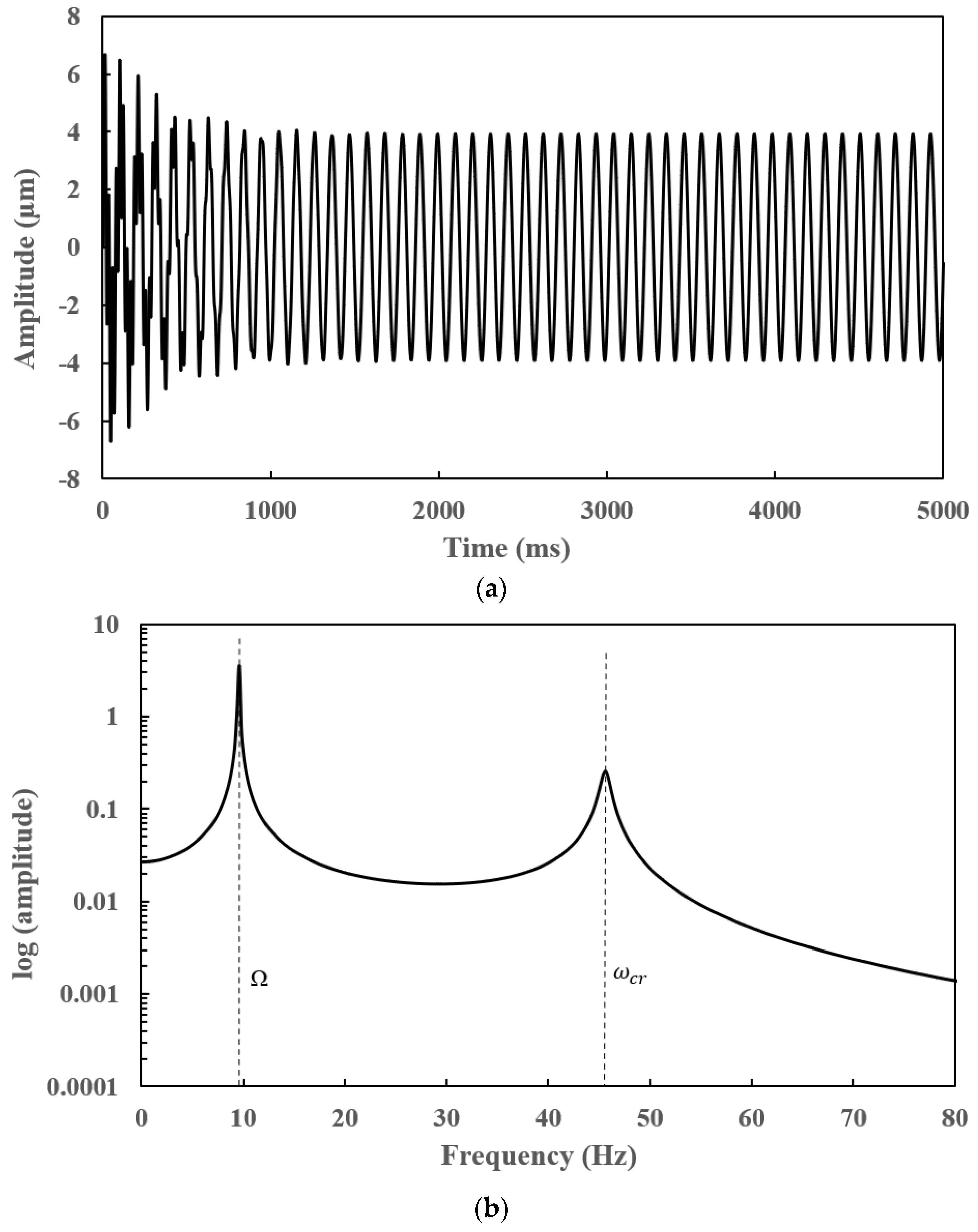
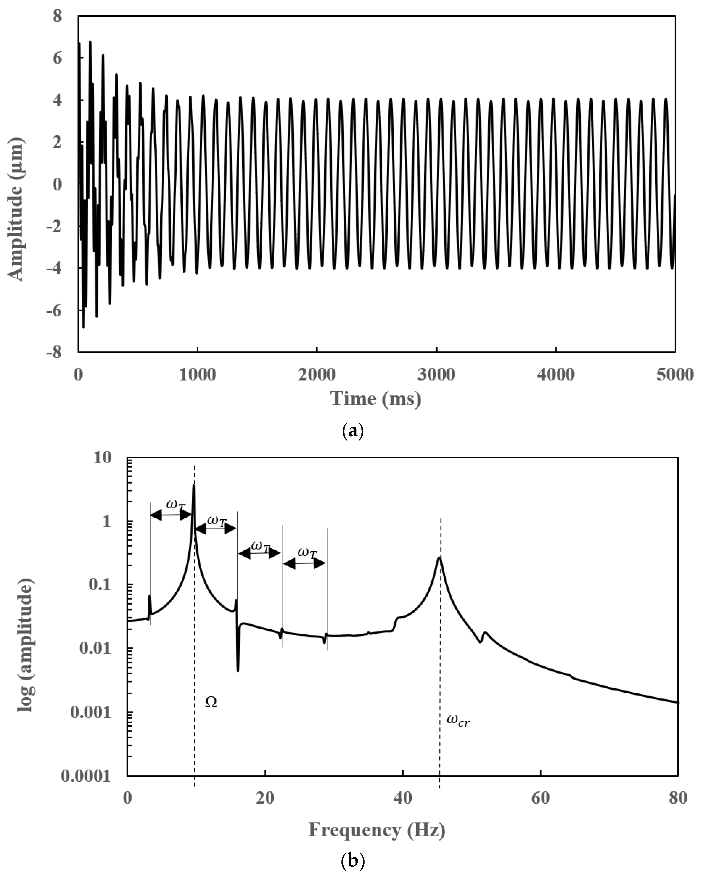
Steady-state time and frequency responses of an uncracked and slant-cracked EG rotor-bearing system for normalised crack depth ( α ) ¯ = 0.3 at L c ¯   = 9.5 are shown in Figure 8 and Figure 9. Steady-state time responses are obtained using the Houbolt method and the corresponding frequency responses have been obtained using Fast Fourier Transform (FFT). The crack features cannot be confirmed from the steady-state time signals since the amplitudes of steady-state time responses, shown in Figure 8a and Figure 9a, are similar. Therefore, the corresponding frequency spectra are used to detect the crack in the rotor. The first peak at 9.55 Hz, shown in Figure 8b and Figure 9b, represents the rotor speed, and the second peak at 47.21 Hz and 46.41 Hz represents the critical speeds of the uncracked and cracked EG rotor-bearing system, respectively. The side lobes (subharmonic peaks) are present in Figure 9b due to the presence of a crack. These harmonic peaks are centred on 9.55 Hz (rotor speed of the shaft) with an interval frequency corresponding to the breathing torsional frequency ω T = 40 rad/s. The frequency of the harmonic peaks of the steady-state frequency spectra can be represented by ω n = Ω ± n ω T ; n = 0, 1… [26]. However, the subharmonic peaks are not present in Figure 8b as the crack is not present in the EG shaft. ω c r is the critical speed of the slant-cracked EG rotor-bearing system.
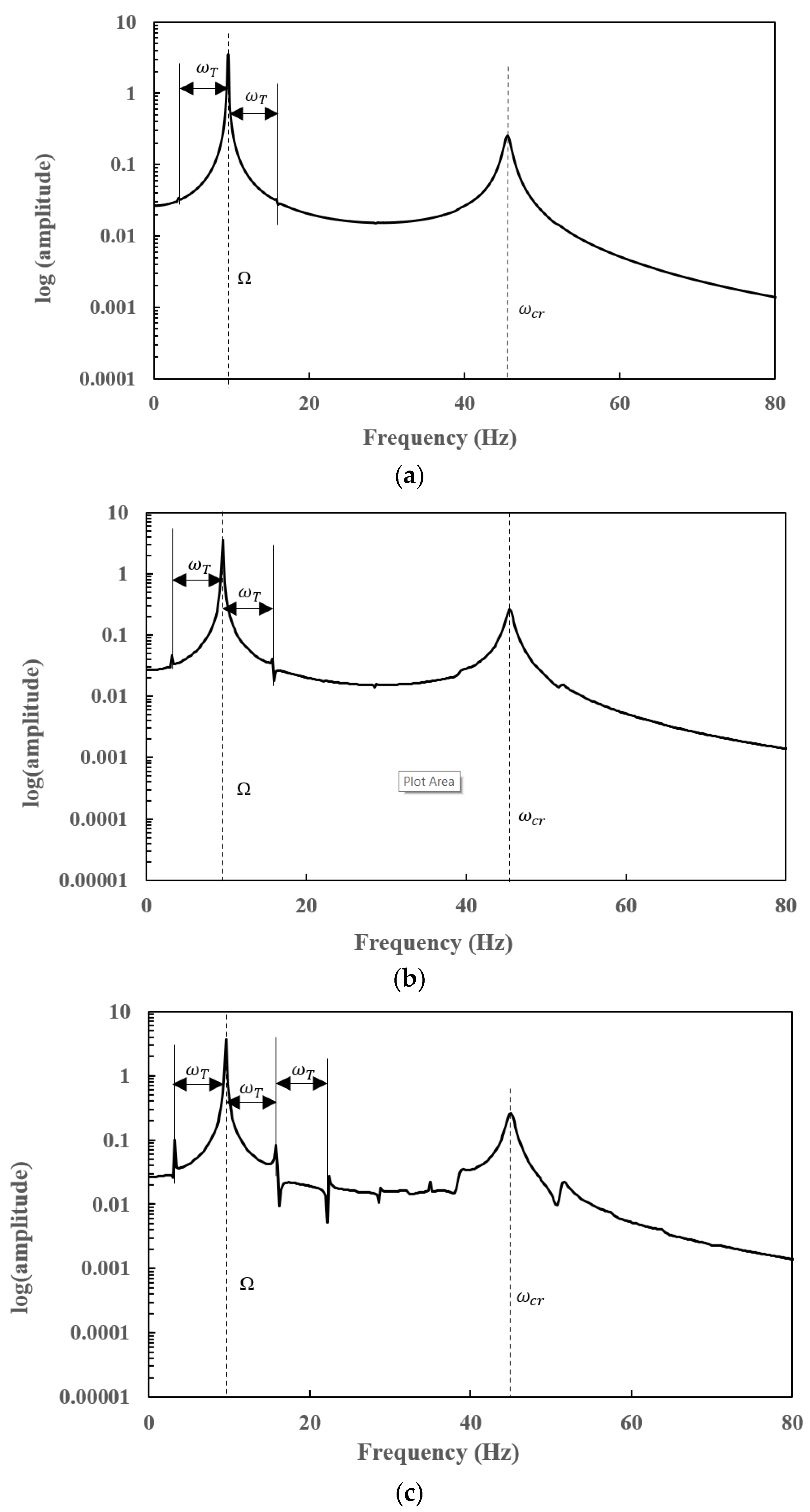
The frequency spectra of a slant-cracked EG rotor-bearing system for different normalised crack depths are shown in Figure 10a–c. The subharmonic peaks, shown in Figure 10a–c, are centred on 9.55 Hz (60 rad/s) with an interval frequency of 6.37 Hz, which is the same as the torsional frequency ω T = 40 rad/s. Although the subharmonic peaks are centred on 9.55 Hz (60 rad/s), the amplitude of the subharmonics is not clearly visible on the frequency spectra when the crack depth α ¯ = 0.1. However, the amplitude of the subharmonics when the crack depth α ¯ = 0.4 is enormous compared to the sub-harmonic frequencies at α ¯ = 0.1, 0.2 and 0.3. The amplitude of the harmonic peaks increases with increase in the crack depth. Therefore, it is possible to determine the severity of the crack using frequency spectra of an EG rotor-bearing system.
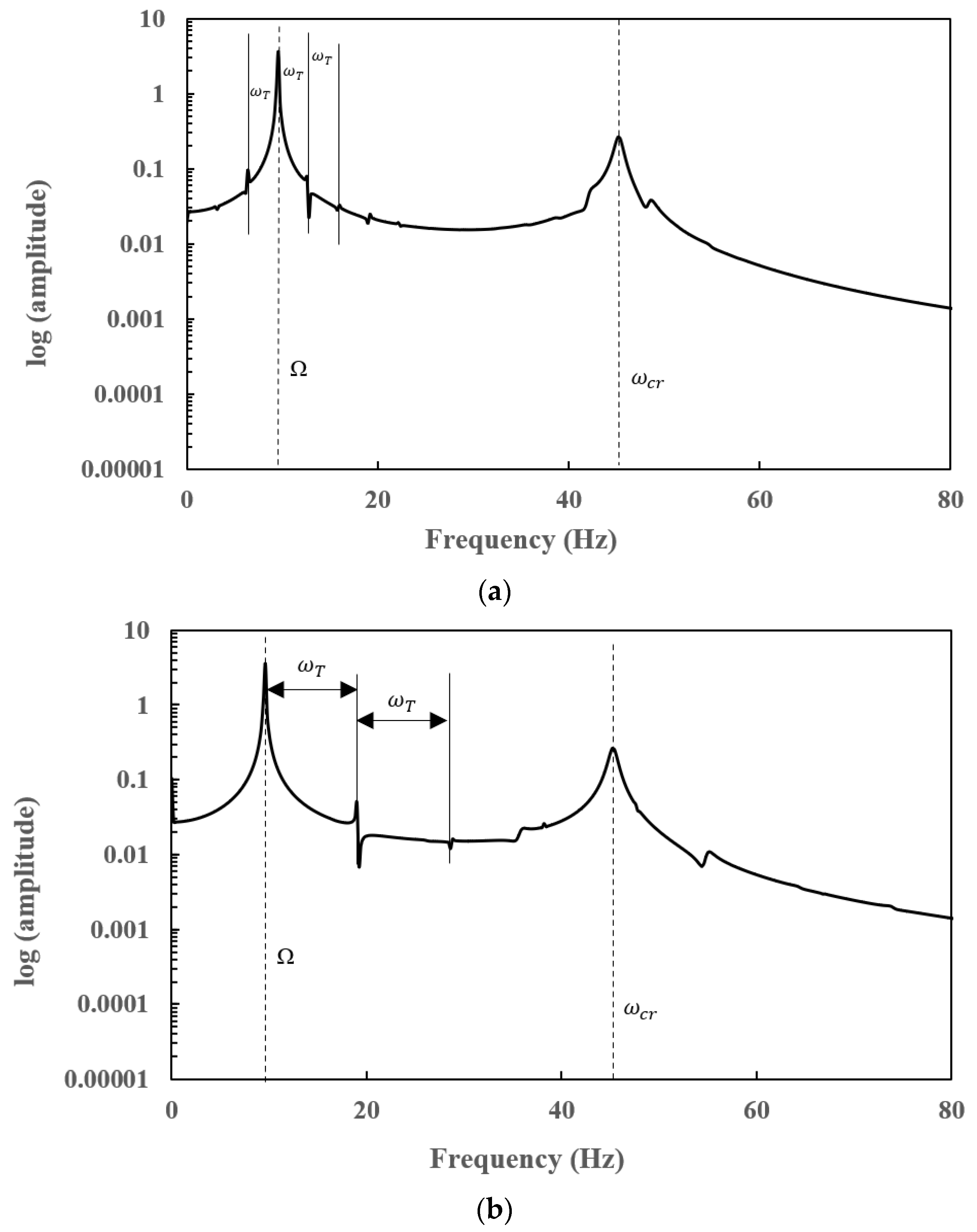
Steady-state responses of slant-cracked EG rotor-bearing systems have been computed for different torsional frequencies and are represented in Figure 11a,b. From the time responses, the frequency of the torsional vibration cannot be indicated, however it is possible to identify the crack through the FFT plot. The subharmonics are centred on 9.55 Hz (60 rad/s), in Figure 11a,b, at an interval frequency of 3.18 Hz (20 rad/s) and 9.55 Hz (60 rad/s), respectively.
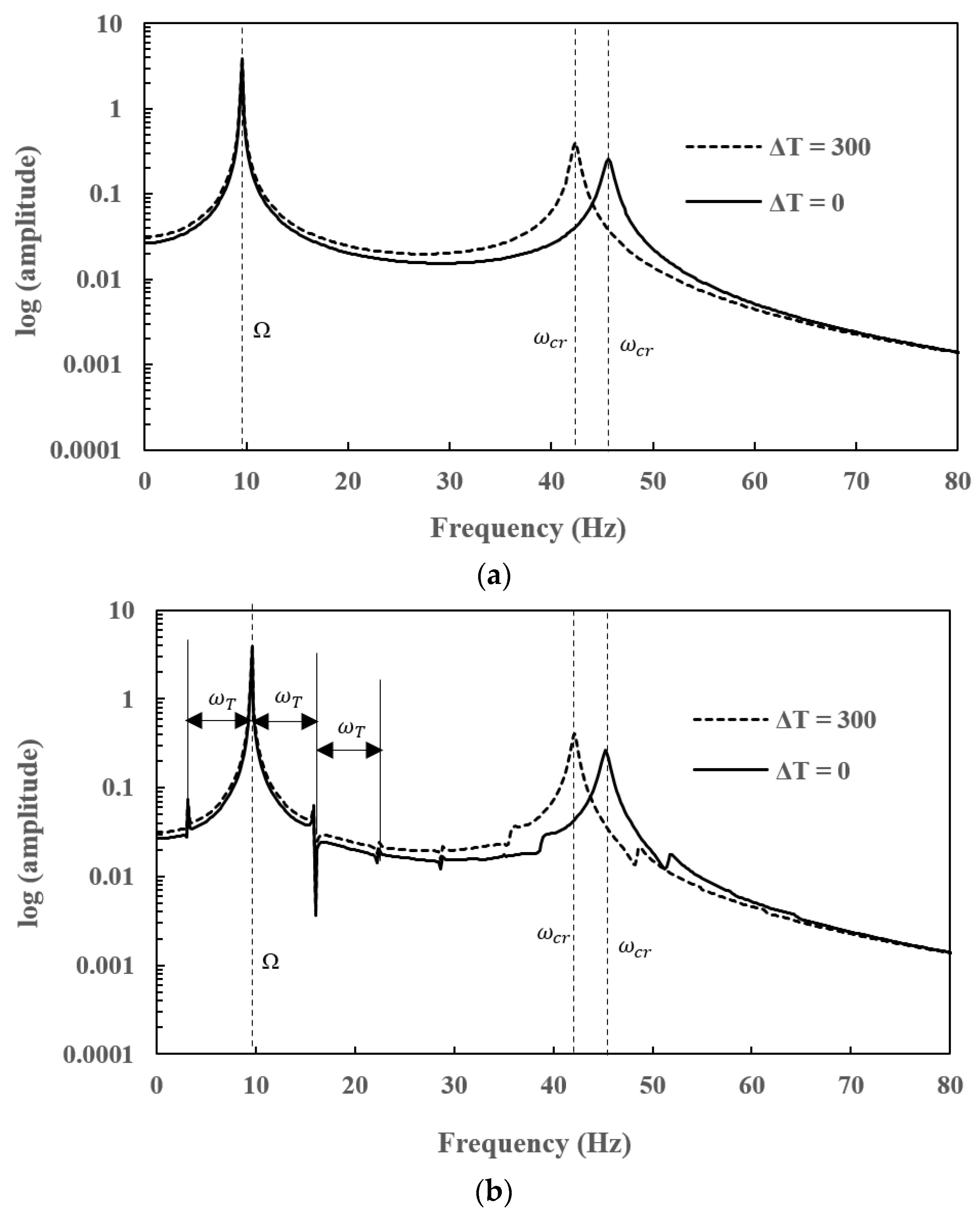
In Figure 12a,b, steady-state frequency responses of uncracked and cracked EG rotor-bearing systems have been depicted at ΔT = 0 and ΔT = 300 K. The amplitude of the FFT at ΔT = 300 K is higher compared to the FFT at ΔT = 0. The first peak of the uncracked and cracked FFT at ΔT = 0 and ΔT = 300 K coincides as the rotor speed is same in both the cases, however the critical speed of the rotor system is lower when the EG shaft is subjected to temperature as the stiffness of the rotor system decreases with the increase in temperature gradient. Therefore, the second peaks shown in Figure 12a,b do not coincide. The side lobes or sub-harmonic peaks appear in the frequency responses when the crack is present.

7.4. Transient Responses of a Slant-Cracked EG Rotor-Bearing System

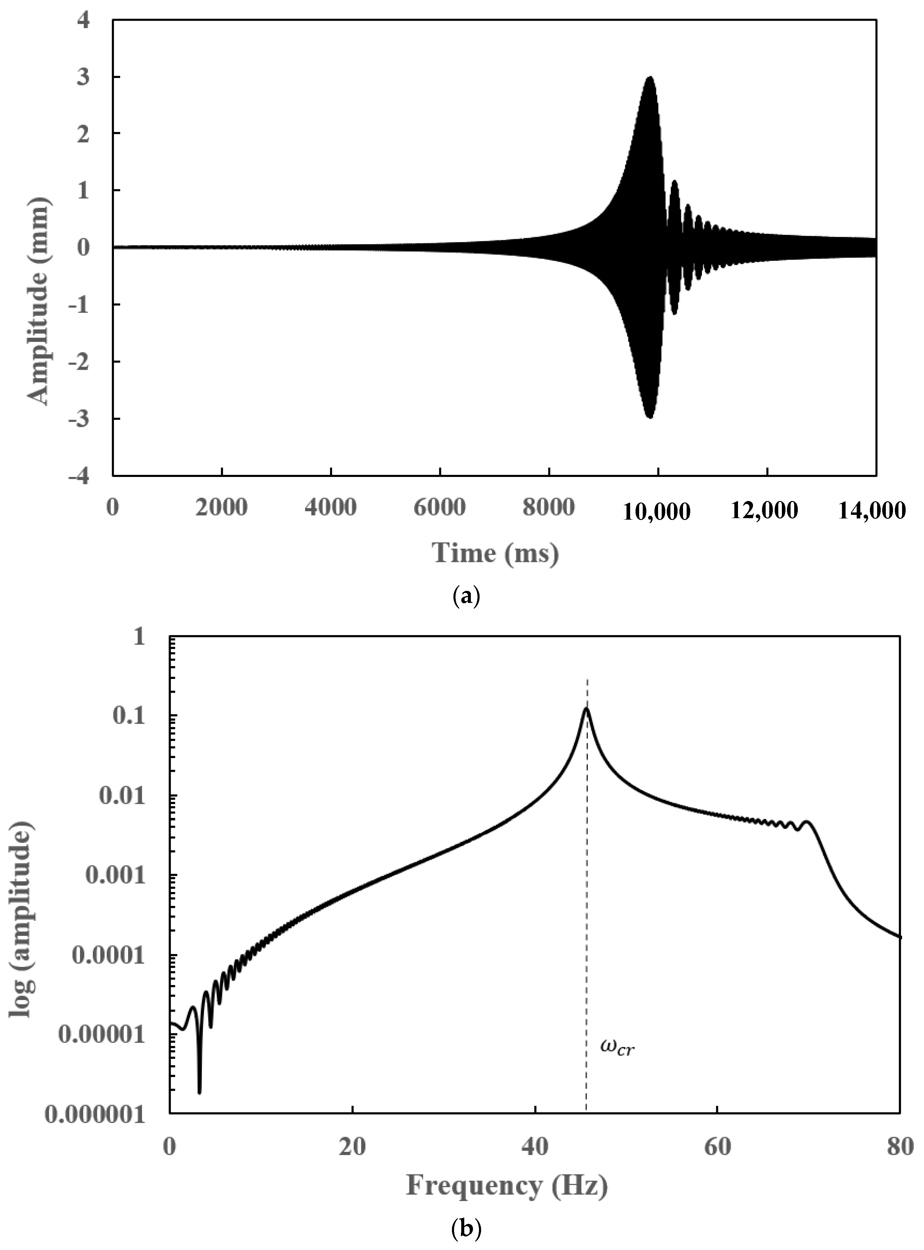
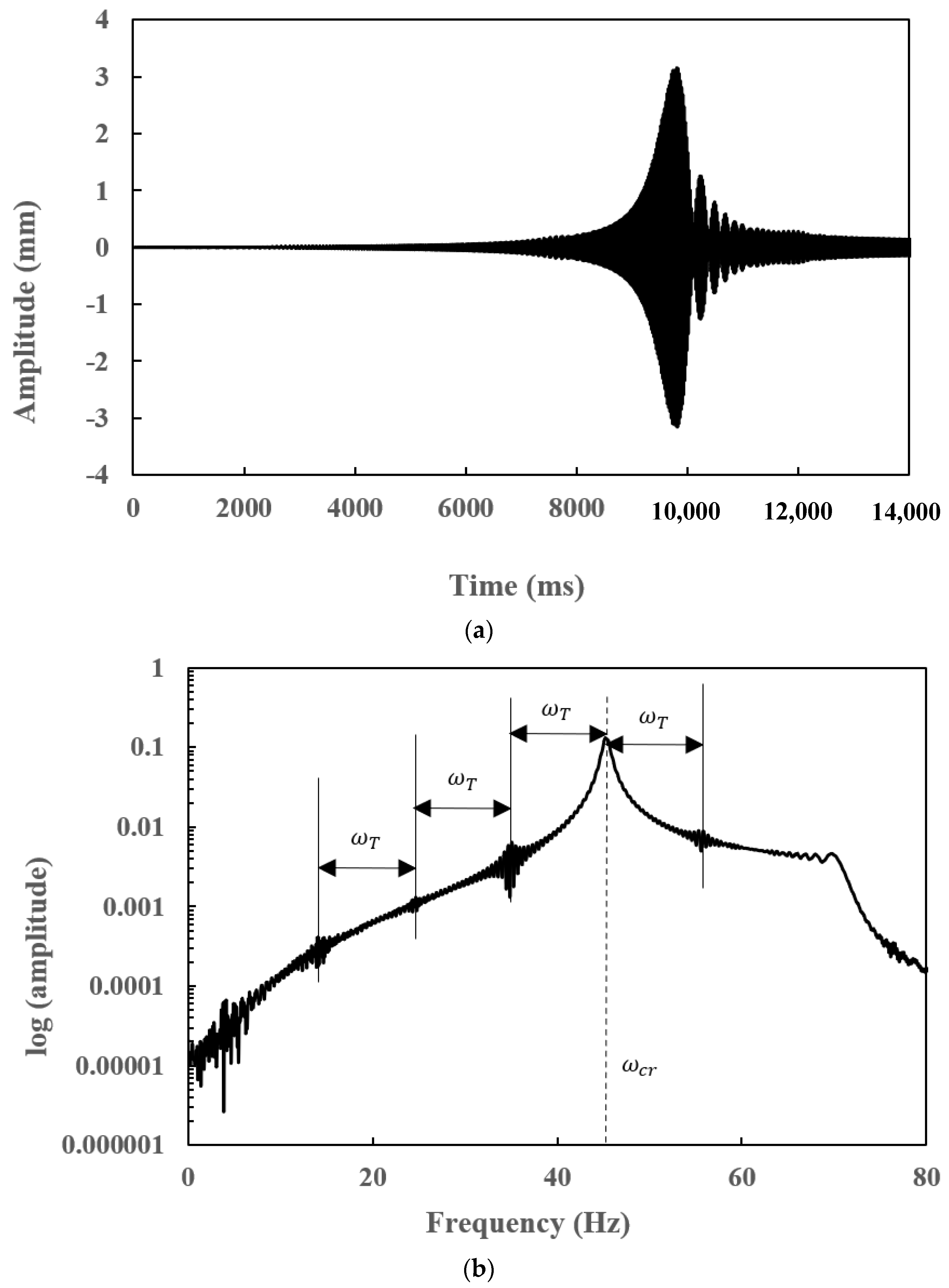
Detection of crack through transient response of a rotor system is as important as steady state response when the rotor starts or stops quite frequently, as in case of aircraft engines. The transient responses of the uncracked and cracked EG rotor-bearing systems passing through the critical speed are depicted in Figure 13 and Figure 14. The transient time response is modelled using the Houbolt method with a time step of 0.001 s. The amplitude of vibration increases when the crack is present. However, no obvious symptoms of crack are observed. However, the crack features can be identified through the frequency response of the uncracked and cracked EG rotor-bearing system. The first critical speed of the uncracked EG rotor is 296.6 rad/s and slant-cracked EG rotor system for α ¯ = 0.3 is 291.593 rad/s. Therefore, the peaks, shown in Figure 13b and Figure 14b, are exactly located at 47.21 Hz and 46.41 Hz, respectively. The subharmonic peaks, shown in Figure 14b, are centred on 46.41 Hz with an interval frequency of 10.34 Hz, which is equal to torsional breathing frequency of the crack, ω T = 65 rad/s. The side lobes in the frequency spectra confirm the presence of the crack. The frequency of harmonic peaks of the transient frequency spectra are represented by ω n = ω c r ± n ω T ; n = 0, 1…, ω c r is the critical speed of the EG rotor, which confirm the published results of the uniform shaft having a slant crack [29].
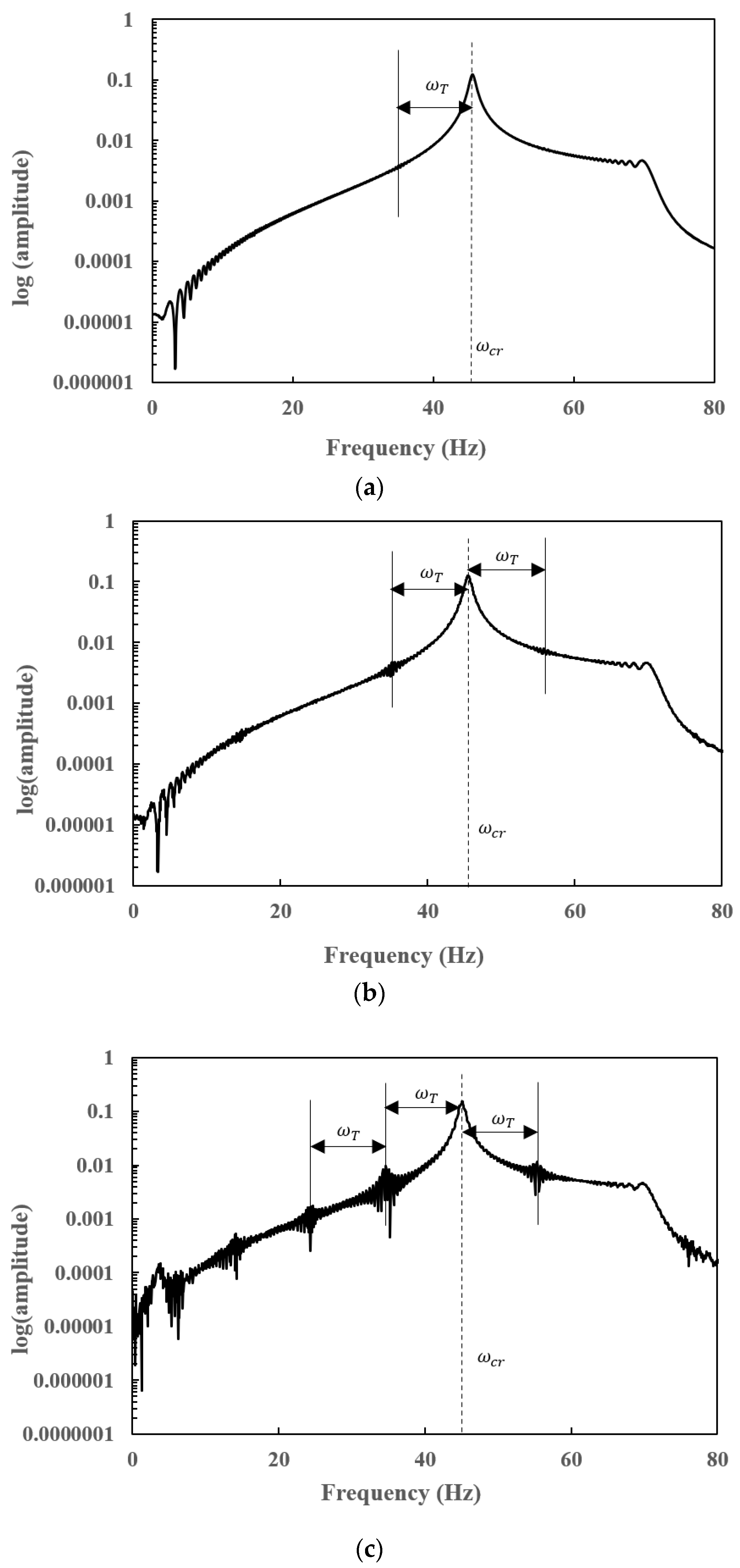
The first critical speeds of the EG rotor when α ¯ = 0.1, 0.2 and 0.4 are 296.254 rad/s, 294.668 rad/s and 285.741 rad/s, respectively. Therefore, it has been observed from Figure 15a–c that subharmonic peaks are centred on (critical speeds of slant-cracked EG rotors) 47.15 Hz, 46.90 and 45.48 Hz, respectively, with an interval frequency of 10.34 Hz, which is equal to the torsional frequency ω T = 65 rad/s. When the crack depth is α ¯ = 0.4, the amplitude of the subharmonics is high, whereas the amplitude of the harmonics is low when crack depth α ¯ = 0.1. Hence, it is also possible to detect the severity of the crack in the accelerated system, as in case of the unaccelerated system.
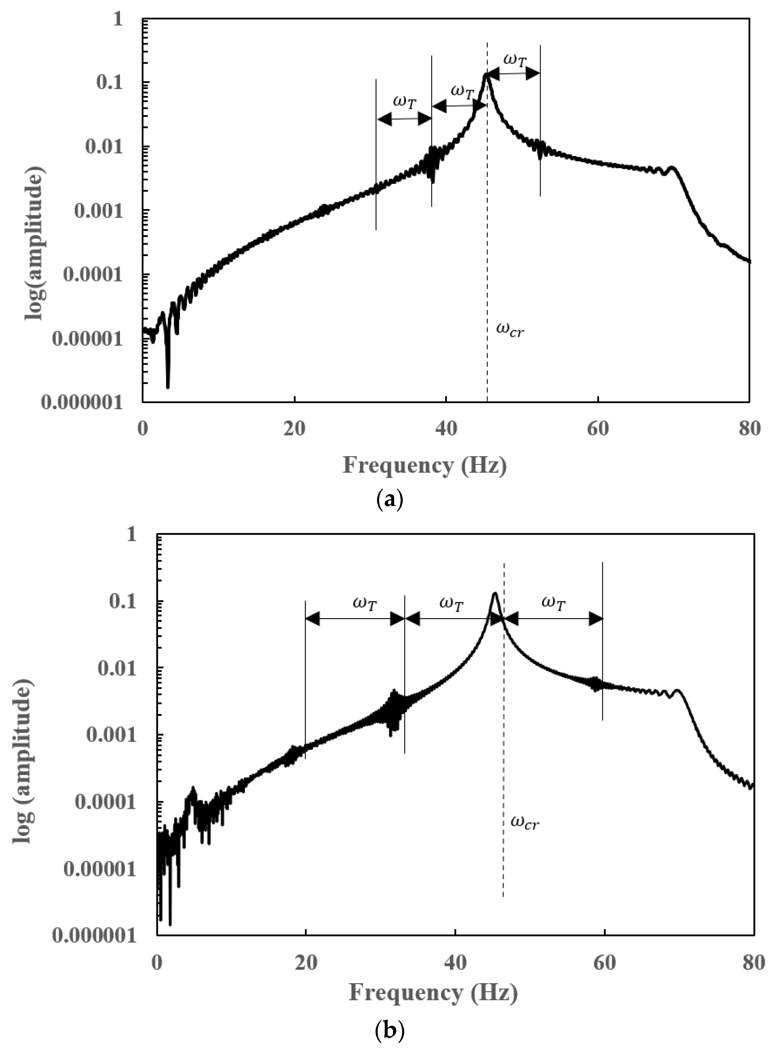
The transient frequency responses of the cracked EG rotor-bearing system have been computed in Figure 16a,b for torsional frequency = 45 rad/s and 85 rad/s. From Figure 16a,b, it is found that the crack breathing frequency is an important parameter to identify the crack in an FG rotor system through the FFT plot.
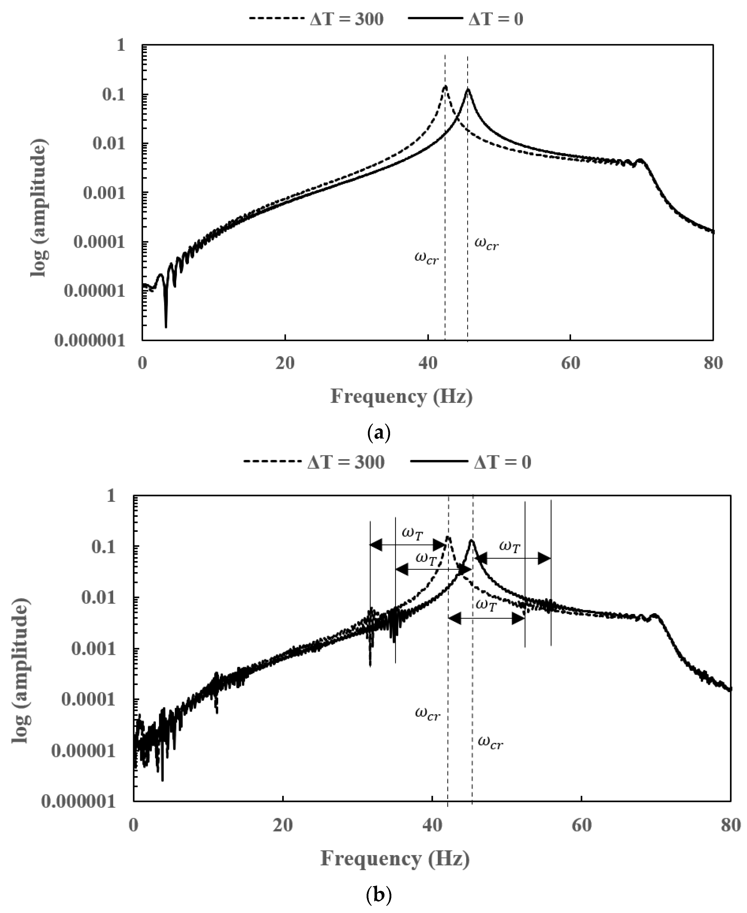
The presence of a crack can be detected even when the EG shaft is subjected to temperature gradients. Transient frequency spectra of an uncracked and cracked EG rotor-bearing system have been represented in Figure 17a,b for different thermal gradients. The amplitude of the frequency spectra at ΔT = 300 K is higher than the amplitude at ΔT = 0. As the first critical speeds of the uncracked and cracked EG rotor-bearing system at ΔT = 0 and ΔT = 300 K are different, the split between the first peaks is observed in Figure 17a,b. The subharmonic peaks are visible in the frequency responses when the crack is present.

8. Conclusions

The dynamic analysis of a slant-cracked EG rotor-bearing system has been carried out using the finite element method to investigate the influence of a slant crack on natural frequencies, steady-state and transient responses. Exponential law is used to grade the material properties along the radial direction of an EG shaft, and exponential temperature distribution law is used for temperature gradation across the cross-section. The effect of crack depth, thermal gradient, crack location, torsional frequency, rotor speed, and angular acceleration on eigenfrequencies and dynamic responses have been investigated, and the following important conclusions are drawn from the analysis.
  • The decrease in natural frequencies with an increase in crack depth is significant when a crack is located near the disc or far from the bearings. The stiffness of the cracked EG rotor is reduced due to the presence of a slant crack.
  • The percentage decrease in the natural frequency is less when a slant crack is present near the bearings compared to the percentage decrease in natural frequency when a slant crack is near the disc. The reduction in stiffness of the EG shaft is compensated by the bearing stiffness when a crack is present near the bearings. Therefore, the natural frequencies of an EG rotor-bearing system are hardly affected when a slant crack is present near the bearings.
  • Natural frequencies of the EG rotor-bearing system decrease with the increase in the crack depth as the stiffness is affected. The increase in temperature gradient of the EG rotor decreases the stiffness as the Young’s modulus is affected. Therefore, the stiffness of a cracked EG rotor-bearing system is furthermore reduced due to an increase in the thermal gradients. The sudden drop in the natural frequencies for different crack depths at higher thermal gradients has also been observed for this reason.
  • Subharmonic peaks are found to be centred on the operational speed at an interval frequency corresponding to the torsional crack breathing frequency in steady-state frequency spectra of a slant-cracked EG rotor-bearing system. The amplitude of the harmonic peaks is increased with an increase in crack depth. Hence the severity of the crack could be identified through the sub-harmonic peaks.
  • The frequency spectrum of the transient response of a slant-cracked EG rotor-bearing system is found to have the subharmonic frequencies centred on the critical speed of the rotor system at an interval frequency corresponding to the torsional frequency corresponds to crack breathing frequency. The presence of subharmonics on the frequency spectra confirms the presence of the crack in the EG rotor.
Since a slant crack may develop due to excessive torsional vibrations of rotor systems, which is possible during the start-up and shutdown of machines, it is essential to detect the crack through vibration response to avoid catastrophic failures. From the present study, a slant crack could be detected through steady state and transient responses of an EG rotor system by extracting the subharmonic peaks corresponding to crack breathing frequency. However, for crack depths below 0.1, other detection techniques need to be explored. The work presented in this paper is based on the theoretical validations, and experiments are being planned for the near future.

Author Contributions

Conceptualization, P.S.; methodology, P.S. and A.B.; validation, P.S. and A.B.; writing—original draft preparation, A.B.; writing—review and editing, P.S., G.C. and R.C. All authors have read and agreed to the published version of the manuscript.

Funding

This research received no external funding.

Institutional Review Board Statement

Not applicable.

Informed Consent Statement

Not applicable.

Data Availability Statement

Not applicable.

Conflicts of Interest

The authors declare no conflict of interest.

References

  1. Birman, V.; Byrd, L. Modeling and Analysis of Functionally Graded Materials and Structures. Appl. Mech. Rev. 2007, 60, 195–216. [Google Scholar] [CrossRef]
  2. Koizumi, M. FGM activities in Japan. Compos. Part B Eng. 1997, 28, 1–4. [Google Scholar] [CrossRef]
  3. Jha, D.; Kant, T.; Singh, R. A critical review of recent research on functionally graded plates. Compos. Struct. 2013, 96, 833–849. [Google Scholar] [CrossRef]
  4. Nejad, M.; Jabbari, M.; Hadi, A. A review of functionally graded thick cylindrical and conical shells. J. Comput. Appl. Mech. 2017, 48, 357–370. [Google Scholar]
  5. Simsek, M. Static analysis of a functionally graded beam under a uniformly distributed load by Ritz method. Int. J. Eng. Appl. Sci. 2009, 1, 1–11. [Google Scholar]
  6. Aydogdu, M.; Taskin, V. Free vibration analysis of functionally graded beams with simply supported edges. Mater. Des. 2007, 5, 1651–1656. [Google Scholar] [CrossRef]
  7. Nguyen, T.; Vo, T.; Thai, H. Static and free vibration of axially loaded functionally graded beams based on the first-order shear deformation theory. Compos. Part B Eng. 2013, 55, 147–157. [Google Scholar] [CrossRef] [Green Version]
  8. Pradhan, K.; Chakraverty, S. Free vibration of Euler and Timoshenko functionally graded beams by Rayleigh–Ritz method. Compos. Part B Eng. 2013, 51, 175–184. [Google Scholar] [CrossRef]
  9. Şimşek, M. Fundamental frequency analysis of functionally graded beams by using different higher-order beam theories. Nucl. Eng. Des. 2010, 240, 697–705. [Google Scholar] [CrossRef]
  10. Azadi, M. Free and forced vibration analysis of FG beam considering temperature dependency of material properties. J. Mech. Sci. Technol. 2011, 25, 69–80. [Google Scholar] [CrossRef]
  11. Nelson, H.; McVaugh, J. The Dynamics of Rotor-Bearing Systems Using Finite Elements. J. Eng. Ind. 1976, 98, 593–600. [Google Scholar] [CrossRef]
  12. Nelson, H. A Finite Rotating Shaft Element Using Timoshenko Beam Theory. J. Mech. Des. 1980, 102, 793–803. [Google Scholar] [CrossRef]
  13. Bose, A.; Sathujoda, P. Natural frequency analysis of a functionally graded rotor system using three-dimensional finite element method. Vibroeng. Procedia 2019, 29, 70–75. [Google Scholar] [CrossRef]
  14. Kiani, Y.; Eslami, M. Thermal buckling analysis of functionally graded material beams. Int. J. Mech. Mater. Des. 2010, 6, 229–238. [Google Scholar] [CrossRef]
  15. Mahi, A.; Bedia, E.A.; Tounsi, A.; Mechab, I. An analytical method for temperature-dependent free vibration analysis of functionally graded beams with general boundary conditions. Compos. Struct. 2010, 92, 1877–1887. [Google Scholar] [CrossRef]
  16. Bose, A.; Sathujoda, P. Effect of Thermal Gradient on Vibration Characteristics of a Functionally Graded Shaft System. Math. Model. Eng. Probl. 2020, 7, 212–222. [Google Scholar] [CrossRef]
  17. Dimarogonas, A. Vibration for Engineers; Prentice-Hall: Upper Saddle River, NJ, USA, 1996. [Google Scholar]
  18. Mayes, I.; Davies, W. Analysis of the Response of a Multi-Rotor-Bearing System Containing a Transverse Crack in a Rotor. J. Vib. Acoust. 1984, 106, 139–145. [Google Scholar] [CrossRef]
  19. Dimarogonas, A.; Papadopoulos, C. Vibration of cracked shafts in bending. J. Sound Vib. 1983, 91, 583–593. [Google Scholar] [CrossRef]
  20. Papadopoulos, C. Torsional vibrations of rotors with transverse surface cracks. Comput. Struct. 1994, 51, 713–718. [Google Scholar] [CrossRef]
  21. Papadopoulos, C.; Dimarogonas, A. Coupling of bending and torsional vibration of a cracked Timoshenko shaft. Ing. Arch. 1987, 57, 257–266. [Google Scholar] [CrossRef]
  22. Darpe, A.; Chawla, A.; Gupta, K. Analysis of the response of a cracked Jeffcott rotor to axial excitation. J. Sound Vib. 2002, 249, 429–445. [Google Scholar] [CrossRef] [Green Version]
  23. Ichimonji, M.; Watanabe, S. The dynamics of a rotor system with a shaft having a slant crack: A qualitative analysis using a simple rotor model. JSME Int. J. Ser. 3 Vib. Control Eng. Eng. Ind. 1988, 31, 712–718. [Google Scholar] [CrossRef] [Green Version]
  24. Dias-da-Costa, D.; Valenca, J.; Julio, E.; Araujo, H. Crack propagation monitoring using an image deformation approach. Struct. Control Health Monit. 2016, 24, 1973. [Google Scholar] [CrossRef]
  25. Yao, Y.; Ellen, S.T.; Glisic, B. Crack detection and characterization techniques-An overview. Struct. Control Health Monit. 2014, 21, 1387–1413. [Google Scholar] [CrossRef]
  26. Sekhar, A.; Prasad, P.B. Dynamic analysis of a rotor system considering a slant crack in the shaft. J. Sound Vib. 1997, 208, 457–474. [Google Scholar] [CrossRef]
  27. Sekhar, A.; Mohanty, A.; Prabhakar, S. Vibrations of cracked rotor system: Transverse crack versus slant crack. J. Sound Vib. 2005, 279, 1203–1217. [Google Scholar] [CrossRef]
  28. Prabhakar, S.; Sekhar, A.; Mohanty, A. Detection and monitoring of cracks in a rotor-bearing system using wavelet transforms. Mech. Syst. Signal Process. 2001, 15, 447–450. [Google Scholar] [CrossRef]
  29. Prabhakar, S.; Sekhar, A.; Mohanty, A. Transient lateral analysis of a slant-cracked rotor passing through its flexural critical speed. Mech. Mach. Theory 2002, 37, 1007–1020. [Google Scholar] [CrossRef]
  30. Sathujoda, P.; Batchu, A.; Obalareddy, B.; Canale, G.; Maligno, A.; Citarella, R. Free Vibration Analysis of a Thermally Loaded Porous Functionally Graded Rotor–Bearing System. Appl. Sci. 2020, 10, 8197. [Google Scholar] [CrossRef]
  31. Sathujoda, P.; Obalareddy, B.; Batchu, A.; Canale, G.; Maligno, A.; Citarella, R. Effect of Corrosion on the Natural and Whirl Frequencies of a Functionally Graded Rotor-Bearing System Subjected to Thermal Gradients. Materials 2020, 13, 4546. [Google Scholar] [CrossRef]
  32. Gayen, D.; Chakraborty, D.; Tiwari, R. Whirl frequencies and critical speeds of a rotor-bearing system with a cracked functionally graded shaft–Finite element analysis. Eur. J. Mech. A/Solids 2017, 61, 47–58. [Google Scholar] [CrossRef]
  33. Gayen, D.; Chakraborty, D.; Tiwari, R. Free Vibration Analysis of Functionally Graded Shaft System with a Surface Crack. J. Vib. Eng. Technol. 2018, 6, 483–494. [Google Scholar] [CrossRef]
  34. Bose, A.; Sathujoda, P.; Canale, G. Natural frequency analysis of a functionally graded rotor-bearing system with a slant crack subjected to thermal gradients. Int. J. Turbo Jet-Engines 2021. [Google Scholar] [CrossRef]
  35. Shen, H. Functionally Graded Materials; CRC Press: Boca Raton, FL, USA, 2019. [Google Scholar]
  36. Touloukian, Y. Thermophysical Properties of High Temperature Solid Materials; Macmillan: New York, NY, USA, 1967. [Google Scholar]
  37. Reddy, J.; Chin, C. Thermomechanical analysis of functionally graded cylinders and plates. J. Therm. Stresses 1998, 21, 593–626. [Google Scholar] [CrossRef]
  38. Qian, G.; Gu, S.; Jiang, J. The dynamic behaviour and crack detection of a beam with a crack. J. Sound Vib. 1990, 138, 233–243. [Google Scholar] [CrossRef]
  39. Tada, H.; Paris, P.; Irwin, G. The stress analysis of cracks handbook. Del. Res. Corp. 1973, 34, 635. [Google Scholar]
Figure 1. An EG shaft element with an inner radius R i = 0.
Applsci 12 06900 g001
Figure 2. (a) A slant-cracked EG rotor-bearing system (b) An EG shaft element with a slant crack. (c) The cut sectional view of slant crack.
Applsci 12 06900 g002aApplsci 12 06900 g002b
Figure 3. Cross-section of an EG beam.
Applsci 12 06900 g003
Figure 4. Normalised natural frequencies of a steel rotorbearing system with an open crack.
Applsci 12 06900 g004
Figure 5. (a) Steady−state (rotor speed of 60 rad/s) (b) transient time response (angular acceleration of 30 rad/s2) of an uncracked steel rotor−bearing system.
Applsci 12 06900 g005
Figure 6. Variation in natural frequencies of a cracked EG rotor−bearing system for different: (a) crack depths; (b) crack locations.
Applsci 12 06900 g006aApplsci 12 06900 g006b
Figure 7. Variation in natural frequencies for different crack depths at different thermal gradients.
Applsci 12 06900 g007
Figure 8. Steady−state (a) time response and corresponding (b) FFT of an uncracked EG rotor−bearing system with a rotor speed of 60 rad/s.
Applsci 12 06900 g008
Figure 9. Steady−state (a) time response and corresponding (b) FFT of a slant−cracked EG rotor−bearing system with a rotor speed of 60 rad/s, and torsional frequency ( ω T ) = 40 rad/s for α ¯ = 0.3 .
Applsci 12 06900 g009
Figure 10. Steady−state FFT of a slant−cracked EG rotor-bearing system with a rotor speed of 60 rad/s, and torsional frequency ( ω T ) = 40 rad/s for (a) α ¯ = 0.1 (b) α ¯ = 0.2 and (c) α ¯ = 0.4, respectively.
Applsci 12 06900 g010
Figure 11. Steady-state FFT of a slant-cracked EG rotor-bearing system with a rotor speed of 60 rad/s with α ¯ = 0.3 for torsional frequency (a) ω T = 20 rad/s (b) ω T = 60 rad/s.
Applsci 12 06900 g011
Figure 12. Steady−state FFT of (a) uncracked (b) slant−cracked EG rotor−bearing system with a rotor speed (Ω) of 60 rad/s, torsional frequency ( ω T ) = 40 rad/s and, α ¯ = 0.3 at ΔT = 0 and ΔT = 300 K.
Applsci 12 06900 g012
Figure 13. Transient (a) time response and corresponding (b) FFT of an uncracked EG rotor−bearing system with an angular acceleration of 30 rad/s2.
Applsci 12 06900 g013
Figure 14. Transient (a) time response and corresponding (b) FFT of a slant−cracked EG rotor−bearing system with an angular acceleration of 30 rad/s2, and torsional frequency ( ω T ) = 65 rad/s for α ¯ = 0.3 .
Applsci 12 06900 g014
Figure 15. Transient FFT of a slant−cracked EG rotor−bearing system with an angular acceleration of 30 rad/s2, and torsional frequency ( ω T ) = 65 rad/s for (a) α ¯ = 0.1 (b) α ¯ = 0.2 and (c) α ¯ = 0.4, respectively.
Applsci 12 06900 g015
Figure 16. Transient FFT of a slant−cracked EG rotor-bearing system with an angular acceleration of 30 rad/s2 with α ¯ = 0.3 for torsional frequency (a) ω T = 45 rad/s (b) ω T = 85 rad/s.
Applsci 12 06900 g016
Figure 17. Transient FFT of (a) uncracked (b) slant−cracked EG rotor-bearing system with an angular acceleration of 30 rad/s2, torsional frequency ( ω T ) = 65 rad/s and, α ¯ = 0.3 at ΔT = 0 and ΔT = 300 K.
Applsci 12 06900 g017
Table 1. Non-dimensional natural frequencies of an exponentially graded beam.
L/hNon-Dimensional Natural Frequencies
PresentMahi et al. [15]Error%
53.5473.5430.11
203.5893.5840.14
Table 2. Normalised natural frequencies of a uniform rotor-bearing system for different crack depths.
α/DPresentDigitized Values [26]|Difference|
0.10.9990.9990
0.20.9980.9980
0.30.9970.9950.002
0.40.9930.9910.002
0.50.9860.9850.001
Table 3. The amplitude (mm) of the points represented on Figure 5a.
PointsPresentDigitised Values [26]|Difference|
10.0190.0200.001
20.0210.0210
30.0130.0140.001
40.0160.0170.001
50.0150.0150
60.0150.0160.001
70.0150.0150
80.0150.0150
90.0150.0150
100.0150.0150
110.0150.0150
120.0150.0150
Table 4. The amplitude (mm) of the points represented on Figure 5b.
PointsPresentDigitised Values [29]|Difference|
12.8392.8420.003
21.0591.0630.004
30.6520.6520
Table 5. Rotor-bearing data.
Shaft
Length (L)0.5 m
Diameter (D)0.02 m
Disc
LocationMid-span
Mass (m)5.5 kg
Polar moment of inertia (Ip)0.01546 kg m2
Diametral moment of inertia (Id)0.00773 kg m2
Unbalance eccentricity ( e )0.0001 m
Bearing
Bearing Stiffness (Rigid bearings)1010 N/m
Damping100 Ns/m
Crack depth ( α ¯ ) α / D
Crack location ( L c ¯ ) L c / L e
Material PropertiesStainless Steel (SS)Zirconia (ZrO2)
Young’s Modulus (GPa)207.8168
Density (kg/m3)81665700
Poisson’s ratio0.30.24
Table 6. Natural frequencies of an uncracked and cracked EG rotor-bearing system for various finite elements to determine the mesh convergence.
No. of Finite ElementsUncracked (Hz)α/D = 0.1 (Hz)α/D = 0.3 (Hz)
1047.212747.221247.2214
1447.212747.195546.9362
1847.212747.163746.5665
2047.212747.163746.5672
2247.212747.163746.5672
Publisher’s Note: MDPI stays neutral with regard to jurisdictional claims in published maps and institutional affiliations.