Article

Influence of Longitudinal Joint Setting and Synchronous Cooling Zone on High Altitude Region’s Dam Construction

1
State Key Laboratory of Simulation and Regulation of Water Cycle in River Basin, China Institute of Water Resources and Hydropower Research, Beijing 100038, China
2
Department of Structure and Materials, China Institute of Water Resources and Hydropower Research, Beijing 100038, China
*
Authors to whom correspondence should be addressed.
Appl. Sci. 2022, 12(15), 7380; https://doi.org/10.3390/app12157380
Submission received: 13 June 2022 / Revised: 11 July 2022 / Accepted: 15 July 2022 / Published: 22 July 2022
(This article belongs to the Section Civil Engineering)

Abstract

:
The crack problem in mass concrete is a difficult problem to thoroughly solve, especially for the crack of dam construction in high-altitude regions. High altitude regions have the fundamental features of a dry climate and strong solar radiation. When dam construction is performed under these special climate conditions, temperature control and crack prevention become more difficult problems. Based on the high altitude region’s dam construction conditions, the existing temperature control measures were optimized by combining the three-dimensional finite element method. The synchronous cooling zone’s temperature control technique is adopted to lower the temperature gradient in the dam’s height direction, coordinate the deformation of the upper and lower layers, and reduce mutual constraints between the upper and lower layers to further reduce the temperature stress. Calculation results show that the adoption of synchronous cooling zones and the set of longitudinal joints can effectively reduce mutual constraints, increase the safety factor, and prevent cracks. This method can be considered an important reference to dam projects in high-altitude regions.

1. Introduction

Cracks are everywhere in mass concrete structures [1]. The problem of reducing cracks and even thoroughly avoiding cracks is always a concern in the engineering world [2]. Causes that are leading to inevitable cracks in mass concrete mainly include [3,4,5,6,7,8,9,10,11,12]: (1) the complexity of crack formation causes and the existence of various factors in the construction process make it difficult to master and predict the formation process of cracks accurately; (2) the characteristics of concrete materials are not understood deeply, the safety margin of temperature control measures designed in the actual engineering is not high enough and causes crack formation, and mechanism are not analyzed thoroughly; and (3) it is difficult to have significant breakthroughs in new technologies and theories therefore, more research into construction is needed.
Although cracks in mass concrete cannot be thoroughly solved, building a dam on the world roof (Tibet) is more challenging. Its particular climate conditions make temperature control and crack prevention of concrete more difficult. Wu and Zhou only briefly introduced the temperature control measurement adopted in the concrete construction of hydropower stations in lower high altitude area [13,14]. Their method was still a conventional temperature control measure. Liao introduced concrete construction technology in cold areas. However, the cooling water pipe was not used in this project [15]; Yang [16], Yu and Li [17] did not mention the stages and zoning of concrete cooling.
The climate features (i.e., dry climate, cold winter, cool summer, great daily range of temperature, long low-temperature season) make crack prevention more complex. The intense solar radiation in plateau regions seriously affects the crack prevention of concrete. Therefore, this paper studies the temperature control and crack prevention technology of mass concrete suitable for large temperature differences and strong radiation areas with a three-dimensional finite element method based on the Tibet Jiexu (JX) Gravity Dam Project, [18,19,20,21,22,23]. Several essential factors in the high plateau climate were considered: large day–night temperature difference, strong solar radiation on concrete pouring temperature and concrete temperature stress, low-temperature snow mountain melting water on concrete cooling measures, and various temperature control and crack prevention measures. Furthermore, the dam’s temperature stress has been improved by the synchronous cooling zone and longitudinal joints. These results provide references for the construction of similar projects.

2. Materials and Methods

2.1. Finite Element Method of Concrete Temperature Fields

According to heat balance theory, the uniform and isotropic solid temperature field meets the differential equation [4] of Formula (1):
T t = a 2 T x 2 + 2 T y 2 + 2 T z 2 + θ τ
where, T is the temperature (°C), θ is adiabatic temperature rise (°C) of concrete, a is thermal diffusivity (m2·h−1), t is time (day), and τ is age (day).
The recurrence equation for calculating the concrete temperature field can be obtained during the concrete temperature field solution by adopting the finite element method in the spatial domain and the backward differentiation method in the time domain. Based on the functional extremum conditions, the temperature field { T } n at the next moment can be derived from the temperature field { T } n of concrete at the last moment:
[ H ] + 1 Δ t n [ R ] { T n + 1 } 1 Δ t n [ R ] { T n } + { F n + 1 } = 0
where [H] is the thermal conduction matrix, [R] is the thermal conduction supplement matrix, n is the sequence number of the time interval, and Δ t n is the nth time step. {Tn} and {Tn+1} are node temperature arrays, and {Fn+1} is node temperature load array.

2.2. Finite Element Method of Concrete Stress Fields

According to the basic theory of the finite element method in elastic mechanics, the finite element control equation at any time interval Δ t i within any space domain R i can be obtained [4]:
K i Δ δ i = Δ P i G + Δ P i C + Δ P i T + Δ P i S
where, Δ δ i is the node displacement increment Δ P i C is the node force increment caused by creep, Δ P i S is the node force increment caused by drying shrinkage, Δ P i G is the node force increment caused by an external load, and Δ P i T is the internal node increment caused by temperature difference, K i is the stiffness.
According to the basic theory of the finite element method, the following formula can be obtained by superposing element integrations:
Δ P i G = e Δ P i G e ;   Δ P i C = e Δ P i C e ;   Δ P i T = e Δ P i T e ;   Δ P i S = e Δ P i S e ;
K i = e k e
According to the displacement increment Δ δ i within Δ t i calculated from the above formulas, the stress increment of each unit of concrete within the same time interval can be obtained:
Δ σ i = D B Δ δ i e D ( Δ ε i C + Δ ε i T + Δ ε i S )
Δ ε i C is the node deformation caused by creep Δ ε i T is the internal node deformation caused by temperature difference Δ ε i S is the node deformation caused by drying shrinkage.
Finally, the displacement field and stress field of concrete can be obtained by superimposing the displacement increments and stress increments, respectively, within various time intervals:
δ i = N j = 1 Δ δ j     ; σ i = N j = 1 Δ σ j

2.3. Equivalent Heat Conduction Equation with Concrete Cooling Water Pipe

Contact surfaces of concrete with air, water, rocks, and other media transfer heat and eliminate heat. This condition is a highly complex problem that cannot be solved by theoretical methods. It is difficult to solve accurately using the finite element method; thus, only an approximate solution can be obtained. In this study, a cooling water pipe is considered a heat-absorbing medium, the function of which is considered in an average sense. Based on this idea, the concrete equivalent heat conduction equation is obtained as follows:
T t = a 2 T + ( T 0 T w ) Φ t + θ 0 Ψ t
where, T is the temperature (°C), T is the temperature increment (°C), a is thermal diffusivity (m2·d−1), θ 0 is the final adiabatic temperature rise (°C), t is time (day), Tw is cooling water temperature (°C), and T0 is the concrete initial temperature (°C).
Ψ ( t ) = e b ( t τ 0.5 Δ τ ) ( f ( τ + Δ τ ) f ( τ ) )
where, f ( τ ) is the arbitrary function adiabatic temperature rise, t is time (day), τ is age (day), Δ τ is age increment (day).
Φ = e k τ ;   k = 2.09 1.35 η + 0.32 η 2 ;   η = λ L / c w ρ w q w
where, qw, cw, and pw are the flow (m3·h−1), specific heat (kJ·(kg·°C)−1), and density (kg·m−3) of cooling water, respectively; λ is the coefficient of temperature conductivity (kJ·(m·d·°C)−1).
The problem can be simplified via the finite element program and computational grid. Then, the heat emission under the cooling water pipe’s effect and the concrete surface can be calculated.

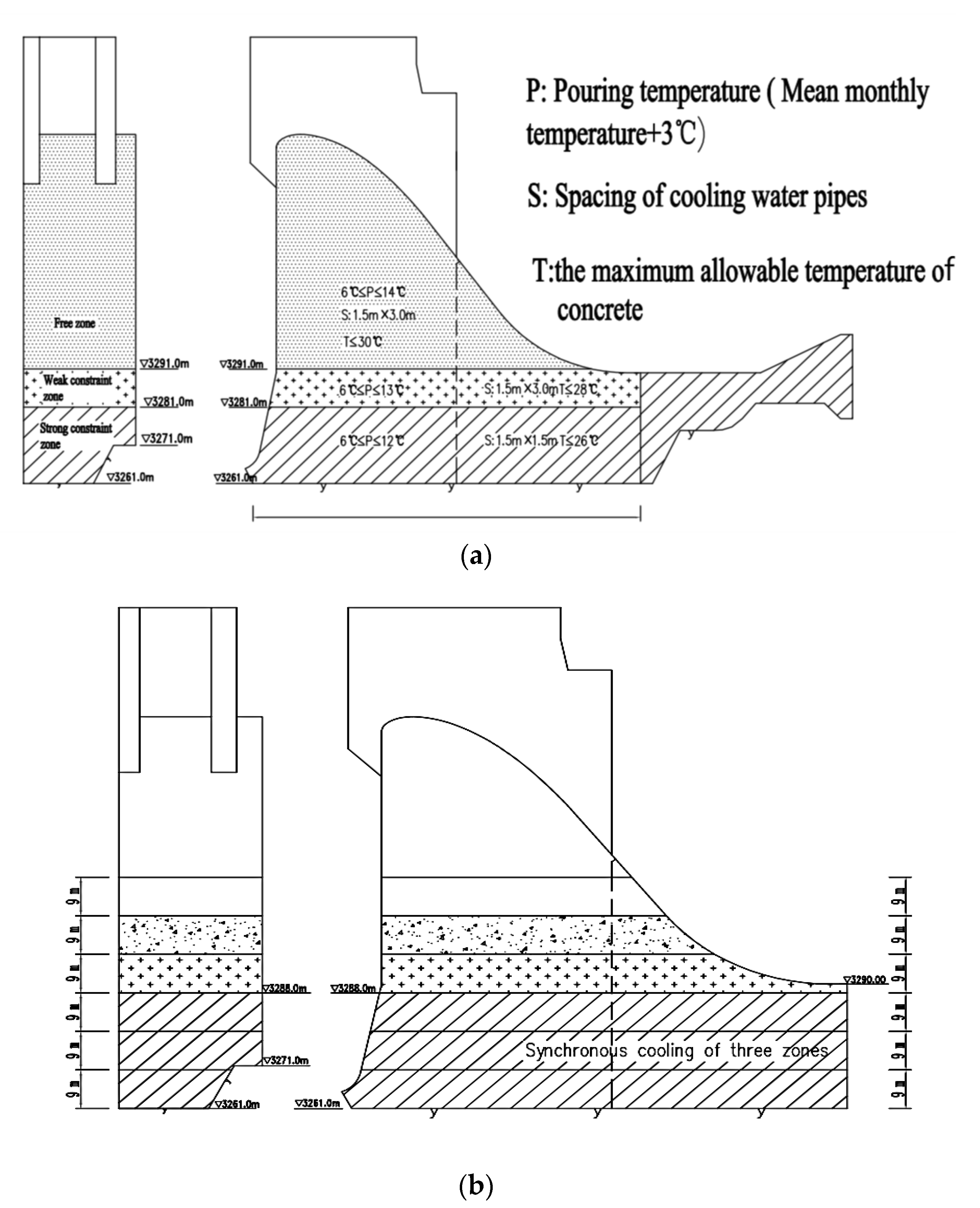
2.4. Construction Features of the JX Gravity Dam

2.4.1. Hydrology and Meteorology

JX Power Station is in a dry climate, cold winter and cool summer, small year temperature difference, and significant daily temperature difference. Thin air and strong solar radiation are the most typical characteristics of these regions. The mean annual temperature of this high-altitude region is 9.3·°C, the difference between the maximum mean monthly temperature and the minimum mean monthly temperature is 16.3·°C, and the minimum reservoir bottom temperature of JX Hydropower Station is about 5.4·°C. The difference between the maximum mean monthly temperature and the target or stable temperature is 6.6·°C. These unique high-altitude climate conditions make temperature control and crack prevention measures more distinct during construction, and temperature control is more difficult.

2.4.2. Material Parameters

JX Hydropower Station is the second hydropower station in the high-altitude region. Compared with the constructed Zangmu (ZM) Hydropower Station with a very similar scale and structure, JX Hydropower Station has the same high-altitude weather conditions. However, the thermodynamic parameters of concrete differ. For temperature control and crack prevention, the thermal expansion coefficient of JX dam concrete is 9.0 × 10⁻⁶·°C−1 which is equivalent to 1.22 times that of ZM, namely 7.4 × 10⁻⁶·°C−1. The adiabatic temperature rise of the dam concrete is 2.5·°C higher than that of ZM. However, the crack resistance, ultimate tensile value, and tensile strength of concrete are similar to those of ZM. JX dam’s concrete has unfavorable material properties, so the temperature and crack prevention difficulty are far greater than that of ZM. The concrete mix of the dam is shown in Table 1, and some thermodynamic parameters of the concrete are shown in Table 2.
This study uses the large-scale engineering simulation software SAPTIS independently developed by the China Water Resources and Hydropower Research Institute as the main tool, combined with GID, GENMESH, and other pre- and post-processing tools. After 30 years of a development-application-redevelopment-reapplication process, SAPTIS (engineering whole-process thermodynamic simulation) is applied as a mature large-scale concrete engineering whole process, all-factor simulation, and analysis platform. The recently built Xiaowan, Xiluodu, Laxiwa, and Dagang mountain arch dams have all been analyzed in terms of the working characteristics of the construction period and the initial water storage period. SAPTIS was used in the working performance analysis of the water storage operation period. According to incomplete statistics, 85% of concrete dam projects with more than 100 m in height built in the past 20 years have applied SAPTIS. This method is used in the simulation analysis, temperature control design, and safety evaluation of nearly 100 large and medium-sized concrete dams in China, and has achieved good application benefits.

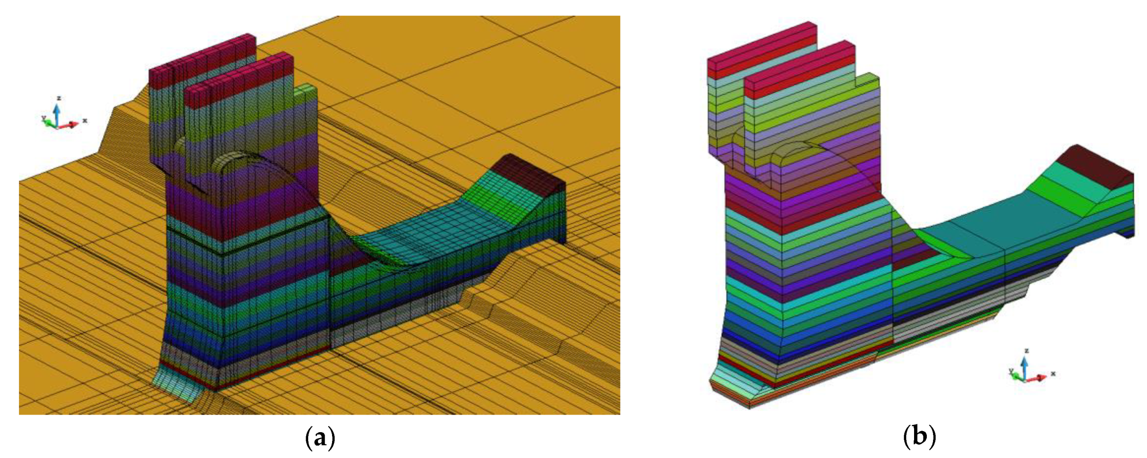
2.5. Numerical Calculation Model

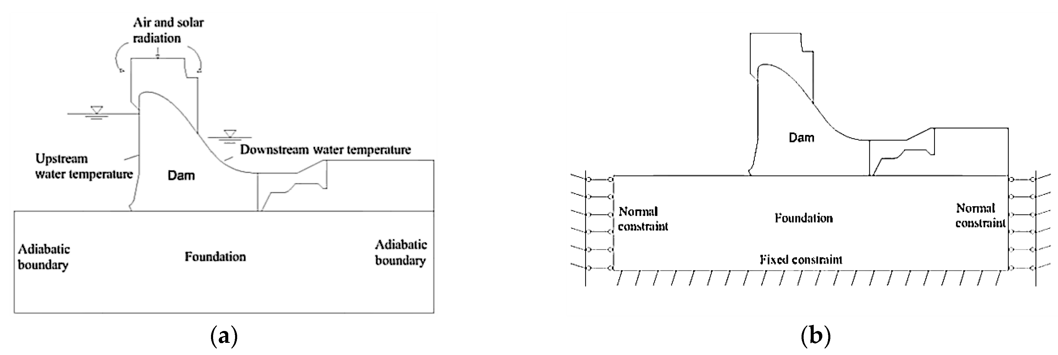
2.5.1. Calculation Models and Boundary Conditions

Since the gravity dam remains stable by its own weight, the entire dam is divided into several dam segments. All dam segments are individually stressed and are not affected by each other. Therefore, a single dam segment is established for numerical calculation. Simulation calculations adopt a three-dimensional finite element method. The model mainly included a dam, stilling pool, and foundation within a specific range under the structure. The three-dimensional finite element model is shown in Figure 1.
For the calculation of the temperature field, local air temperature and solar radiation are considered. The dam’s upstream and downstream are the third boundary, the foundation model’s surrounding and bottom are insulated boundaries, and the upper surface is the third boundary condition. For the calculation of the stress field, the bottom of the foundation is constrained in three directions. The sides of the foundation are unilaterally constrained, and other boundary surfaces are free deformed. Figure 2 shows the boundary conditions for model calculation. Figure 3 shows a cross-sectional view of the dam. Typical point and longitudinal joint are shown in Figure 4.

2.5.2. Calculation Parameter Model

Four-grade concrete is adopted for the dam construction. Here, two parameters with the highest relevance to dam temperature stress are described. The following parameters are obtained according to the test data:
Adiabatic temperature rise model
θ ( τ ) = 26.26 × τ / ( 3.73 + τ )
Elastic modulus model
E ( τ ) = 28.6 × ( 1 e 0.33 × τ 0.334 )
Autogenous volume deformation test data are listed in Table 3, and deformation values between the two ages can be obtained through the spline interpolation function.

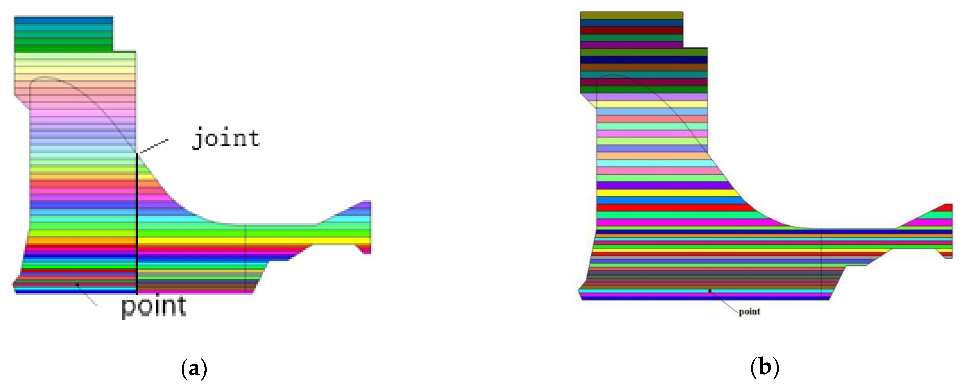
2.5.3. Feature Point and Feature Cross-Section

The presence and absence of the longitudinal joint do not have great significance for the maximum temperature. The maximum temperature in the strong constraint zone is still 26.3 °C when the longitudinal joint scheme is adopted, as shown in Figure 8a. The calculation results of dam concrete temperature and stress with the longitudinal joint show that the maximum stress happened when the maximum temperature dropped to the target temperature (stable temperature). The maximum stress along the river direction is decreased to 1.45 MPa and occurs at an elevation of 3263 m high with 2 m away from the foundation plane. However, the range of significant stresses is reduced in the positions between longitudinal joints and upstream or downstream profiles, as shown in Figures 7b and 8b.

3. Results and Discussion

The maximum bottom width of JX Dam is 96.8 m, and whether to arrange the longitudinal joint along the dam axial direction is a bone of contention among engineers. Some engineers consider that the longitudinal joint may not be arranged along the dam axial direction because the bottom width of JX Dam is smaller than that of ZM. Stress will be decreased; moreover, the scheme of arranging longitudinal joints damages the dam’s integrity, which is bad for project safety. The data show that the material properties of the JX dam body are very different from those of ZM. For example, the adiabatic temperature rise of JX concrete is more than 3 °C higher than that of ZM, and the linear expansion coefficient is about 1.22 times that of ZM, but the elastic modulus and tensile strength are equivalent to that of ZM. These parameters are closely related to temperature control, so the material parameters of JX are relatively unfavorable for crack prevention, and the difficulty of temperature control is greater than that of ZM. It is known that the scale of the two projects is very similar, the section component is the same, and the ZM dam has longitudinal joints. Therefore, from the careful consideration of dam temperature control, construction experience, and operation, it is recommended to set longitudinal joints for the JX dam. Figure 5 shows schematics of the dam with and without the longitudinal joint.

3.1. Temperature Stress without Longitudinal Joint

When there is no longitudinal joint, the bottom of the dam along the river is large. The maximum temperature of concrete 2 m from the bottom of the dam is 26.3 °C, and the maximum stress along the river is 1.71 MPa. The occurrence time of the maximum stress is the time when the concrete temperature reduces to the target temperature (stable temperature), as shown in Figure 6 and Table 4. The dam has the risk of cracking. The maximum stress along the river direction is in the middle position of the strong constraint zone, as shown in Figure 7.

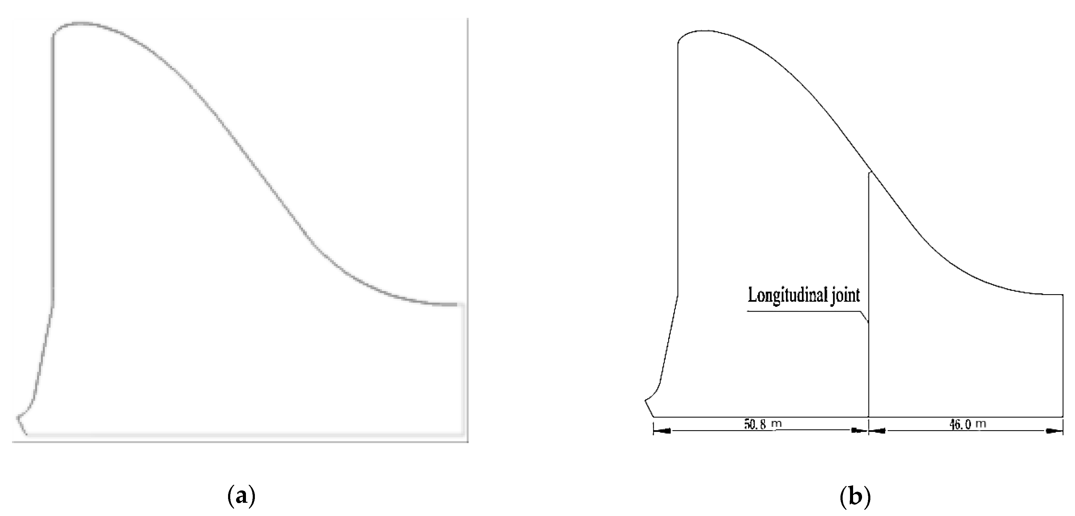
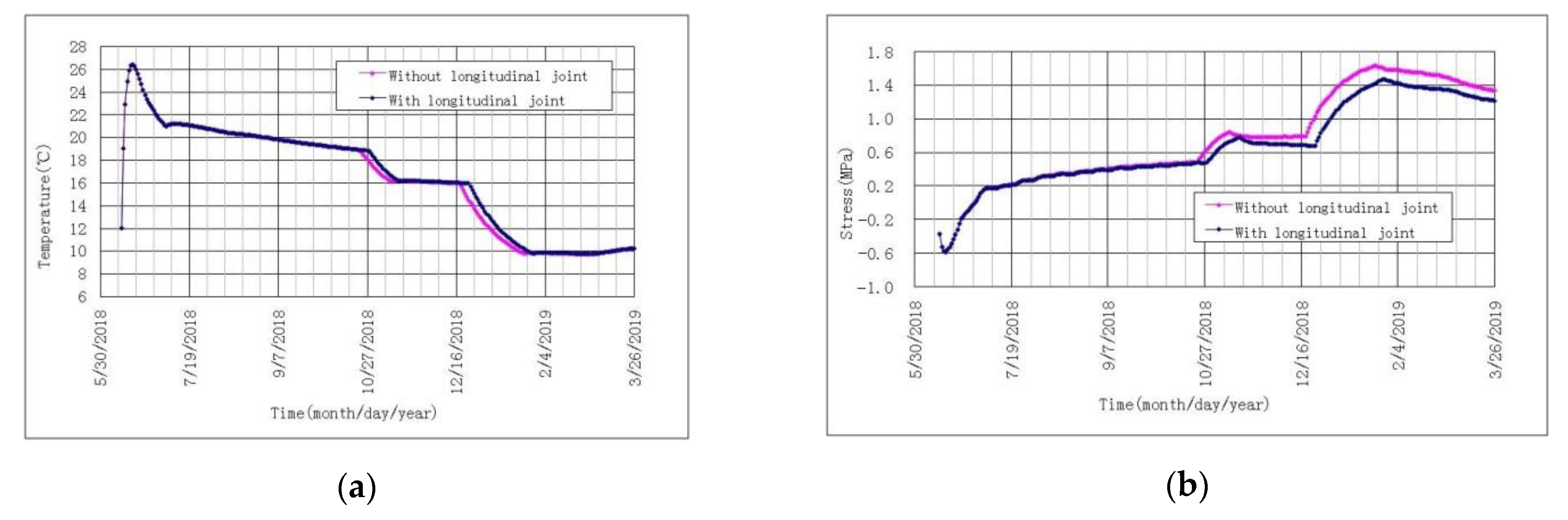
3.2. Temperature Stress with Longitudinal Joint

The presence and absence of the longitudinal joint do not have great significance for maximum temperature. The maximum temperature in the strong constraint zone is still 26.3 °C when the longitudinal joint scheme is adopted, as shown in Figure 8a. The calculation results of dam concrete temperature and stress with the longitudinal joint show that maximum stress still occurs when the maximum temperature drops to the target temperature (stable temperature). The maximum stress along river direction is decreased to 1.45 MPa and occurs at an elevation of 3263 m and 2 m away from the foundation plane. However, the range of significant stresses is reduced in the positions between longitudinal joints and upstream or downstream profiles, as shown in Figure 8b.

3.3. Reasonableness Analysis of Longitudinal Joint Position

Figure 7b shows that the maximum stress is in the middle position of the dam bottom width. Figure 8b shows that the longitudinal joint position is also just in the maximum stress position shown in Figure 7b (i.e., the middle position in the length direction). Figure 7b and Figure 8 show that the stress concentration area of the dam body is significantly smaller after adding longitudinal joints, and the maximum tensile stress is reduced from 1.74 MPa to 1.45 MPa. The longitudinal joint arrangement can shorten the strong constraint zone’s length and reduce the maximum temperature stress along the river direction. Therefore, the proposed position of the longitudinal joint system is reasonable and can meet the safety needs of the project.

3.4. Impact of Synchronous Cooling Zone on the Temperature Stress of the Dam Body

Both the climate conditions and material parameters have adverse impacts on the temperature control and crack prevention of concrete, so only optimization and improvement of temperature control measures can be conducted. The synchronous cooling zone’s research is conducted to optimize the cooling process and scope based on the longitudinal joint arrangement. It decreases the temperature gradient in the dam’s height, the temperature difference between the upper and lower layers of concrete, and the reciprocal constraint and temperature stress. Although the elastic modulus of concrete gradually increases with age, the leading cause of temperature stress is temperature change and constraint. The purpose of setting a synchronous cooling zone is to reduce the mutual restraint between the pouring layers. Figure 9 shows the temperature control measures and the spatial distribution of the cooling mode, while Figure 10 shows the dam foundation’s casting process, strong constraint zone, and optimal cooling process control.
Some definitions are introduced here:
Phase 1 cooling in Figure 10 aims to reduce the concrete’s peak value and control the maximum temperature of concrete. The purpose of medium cooling is to control the temperature rise after phase 1 cooling of concrete and reduce the cooling range of concrete during Phase 2 cooling by slowly cooling in the medium cooling stage; the purpose of Phase 2 cooling is to reduce the grouting temperature.
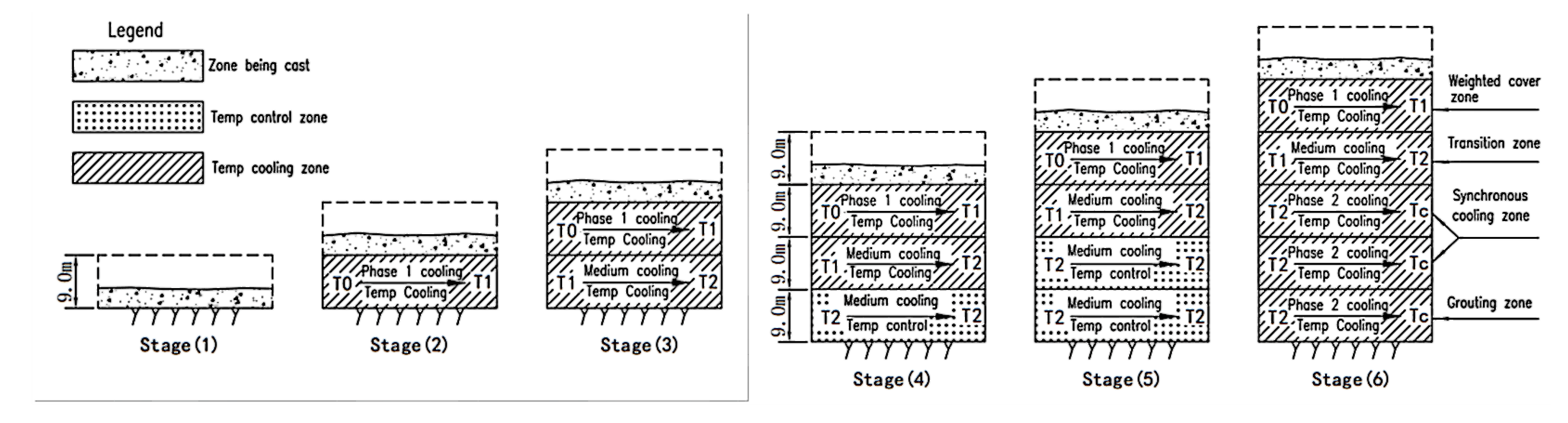
  • The height of a JX Dam grouting zone is 9 m, i.e., each grouted zone is 9 m in height;
  • Grouting zone: The zone where longitudinal joint grouting is to be carried out, generally one zone;
  • Synchronous cooling zone: The zone where cooling is carried out simultaneously and coordinately. When the grouting zone is the first grouted zone at the bottom of the constraint zone, the synchronous cooling zone is two grout zones above the grouting zone, while the other zones are a grout zone above the grouting zone;
  • Transition zone: The zone between the synchronous cooling zone and weighted cover zone, a grouting zone above the synchronous cooling zone;
  • Weighted cover zone: Newly placed concrete zone, a grouting zone above the transition zone.
In scheme 1, the synchronous cooling zone is 9 m in height; in scheme 2, the synchronous cooling zone is 18 m in height; and in scheme 3, the synchronous cooling zone is 27 m.
It can be seen from Table 5 and Figure 11 that:
6.
When the synchronous cooling zone’s height varies, it has a minimal impact on the maximum temperature. The maximum temperatures of the strong constraint zone are all 26.3 °C;
7.
If the synchronous cooling zone is 9 m in height (each grouted zone is 9 m in height), each grouting zone is cooled via cooling water. As the temperature difference and deformation between the upper and lower ground zones do not synchronize, the foundation concrete is under more vital constraints. The maximum stress in the middle of the strong constraint zone is up to 1.58 MPa, while cracks can be easily caused;
8.
If the synchronous cooling zone is 18 m in height, the two grouting zones are cooled in a coordinated manner. The constraint on foundation concrete is obviously reduced by reducing the temperature difference and synchronous deformation between the upper zone and the lower zone. The maximum stress in the middle position is 1.45 MPa. Although the growth of safety factor meets specifications (more than 1.65), the margin is small;
9.
If the synchronous cooling zone’s height is increased to 27 m, the three grouting zones are cooled in a coordinated manner. As the scope of the temperature difference reduction and synchronous deformation increases, the constraint on the foundation concrete is further reduced. The maximum stress in the middle position is reduced to 1.40 MPa, while the safety factor has an apparent increase;
In conclusion, the synchronous cooling zone’s height has a noticeable impact on concrete stress and mainly has a more considerable impact on the concrete in grouting zones 1 and 2 of the strong constraint zone. To reduce the strong constraint zone stress at the end of phase 2 and increase the safety factor, one should make the best efforts to increase the synchronous cooling zone’s height, particularly in the dam’s steep section.

4. Conclusions

  • Due to the particular climate conditions, it is difficult to control the temperature and crack of concrete during the construction period when building a dam in a high-altitude area. Simultaneously, dam construction technology and engineering in low-altitude areas are not suitable for dams in high-altitude areas. Therefore, it is necessary to study technical improvements.
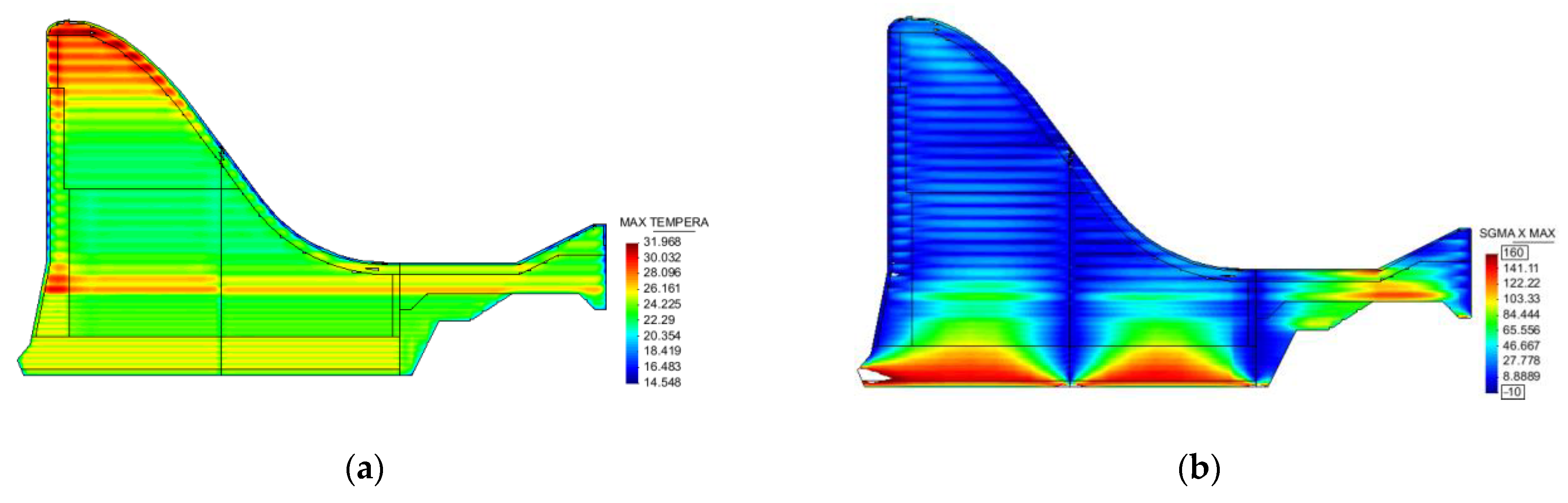
  • When there is no longitudinal joint, maximum stress occurs in the middle of the dam’s length direction. Setting the longitudinal joint in the middle of the length direction at the bottom of the dam can significantly reduce the temperature stress along the river, lower the possibility of cracking, and increase the mass concrete structure’s crack resistance.
  • Furthermore, setting the synchronous cooling zone can make the upper and lower pouring layers deform synchronously, reducing the mutual restraint between the concrete layers and the temperature stress. Meanwhile, the larger the synchronous cooling zone’s height, the more favorable it is to reduce the temperature stress, but the construction schedule requirements of the project should also be considered.

Author Contributions

Conceptualization, J.X. and Z.W.; methodology, Z.W. and J.X.; software, Z.W. and Z.S.; validation, Z.W. and Z.S.; formal analysis, B.Z. and Z.W.; resources, J.X.; data curation, Z.W., Z.S. and B.Z.; writing—original draft preparation, Z.W. and J.X.; writing—review and editing, Z.W. and Z.S.; project administration, Z.W.; funding acquisition, Z.W. All authors have read and agreed to the published version of the manuscript.

Funding

This research was funded by National Key R&D Program of China (2021YFC3090102).

Institutional Review Board Statement

Informed consent was obtained from all subjects involved in the study.

Informed Consent Statement

Informed consent was obtained from all subjects involved in the study.

Data Availability Statement

Not applicable.

Conflicts of Interest

The authors declare no conflict of interest.

References

  1. Lu, L.; Li, X.G. Research and Progress of Control for Mass Concrete Temperature Crack. J. Water Resour. Archit. Eng. 2012, 10, 146–150. [Google Scholar]
  2. Ding, B.Y.; Wang, G.B.; Huang, S.P.; Yue, Y.Z.; Hu, P. A review on causes of cracking in domestic concrete dams and preventive measures. Water Resour. Hydropower Eng. 1994, 4, 12–18. [Google Scholar]
  3. Atiş, C.D. Heat evolution of high-volume fly ash concrete. Cem. Concr. Res. 2002, 32, 751–756. [Google Scholar] [CrossRef]
  4. Zhu, B. Thermal Stresses and Temperature Control of Mass Concrete; Butterworth-Heinemann: Oxford, UK, 2013. [Google Scholar]
  5. Komonen, J.; Penttala, V. Influence of admixture type and concrete temperature on strength and heat of hydration of concrete. In Proceedings of the 10th International Congress on the Chemistry of Cement, Göteborg, Sweden, 2–6 June 1997; pp. 1–8. [Google Scholar]
  6. Konsta-Gdoutos, M.S.; Shah, S.P. Hydration and properties of novel blended cements based on cement kiln dust and blast furnace slag. Cem. Concr. Res. 2003, 33, 1269–1276. [Google Scholar] [CrossRef]
  7. Sioulas, B.; Sanjayan, J.G. Hydration temperatures in large high-strength concrete columns incorporating slag. Cem. Concr. Res. 2000, 30, 1791–1799. [Google Scholar] [CrossRef]
  8. Tank, R.C.; Carino, N.J. Rate constant functions for strength development of concrete. Mater. J. 1991, 88, 74–83. [Google Scholar]
  9. Wang, Z.; Liu, Y.; Zhang, G.; Hou, W. Schematic study on temperature control and crack prevention during spillway tunnel concreting period. Mater. Struct. 2015, 48, 3517–3525. [Google Scholar] [CrossRef]
  10. Wang, Z.; Liu, Y.; Zhang, G.; Yu, S. Sensitivity analysis of temperature control parameters and study of the simultaneous cooling zone during dam construction in high-altitude regions. Math. Probl. Eng. 2015, 2015, 528589. [Google Scholar] [CrossRef]
  11. Wang, Z.-H.; Zhu, Y.-M.; Yu, S.-P. Study on temperature control and crack prevention of thin-walled concrete structures during the construction period. J. Xi’an Univ. Archit. Technol. (Nat. Sci. Ed.) 2007, 6. [Google Scholar] [CrossRef]
  12. Wang, Z.; Liu, Y.; Yu, S. Surface thermal insulation and pipe cooling of spillways during concrete construction period. Math. Probl. Eng. 2014, 2014, 973680. [Google Scholar]
  13. Guo, J. Temperature Control of Mass Concrete in Diversion Channel of Tongzilin Hydropower Station. Water Power 2012, 38, 47–49. [Google Scholar] [CrossRef]
  14. Zhou, Z.Q. Natural Conditions and Major Construction Features of Manla Water Control Project. Water Resour. Hydropower Eng. 2000, 31, 5–7. [Google Scholar]
  15. Liao, C.; Mao, W. Temperature Control Construction Technology of Mass Concrete in High and Cold Regions. Sichuan Water Power 2012, 31, 6–8. [Google Scholar]
  16. Yang, H. Construction Technology of Mass Concrete in High-Altitude Regions. Qinghai Transp. Technol. 2011, 50–51. [Google Scholar] [CrossRef]
  17. Yu, X.; Li, C. The Reason of Concrete Cracking and Control Measures under Severe Environment. Qinghai Electr. Power 2011, 30, 53–55. [Google Scholar]
  18. Bazant, Z.P.; Murphy, W. Creep and shrinkage prediction model for analysis and design of concrete structures-model B3. Matériaux Constr. 1995, 28, 357–365. [Google Scholar]
  19. De Schutter, G. Finite element simulation of thermal cracking in massive hardening concrete elements using degree of hydration based material laws. Comput. Struct. 2002, 80, 2035–2042. [Google Scholar] [CrossRef]
  20. Jin, F.; Chen, Z.; Wang, J.; Yang, J. Practical procedure for predicting non-uniform temperature on the exposed face of arch dams. Appl. Therm. Eng. 2010, 30, 2146–2156. [Google Scholar] [CrossRef]
  21. Léger, P.; Côté, P.; Tinawi, R. Finite element analysis of concrete swelling due to alkali-aggregate reactions in dams. Comput. Struct. 1996, 60, 601–611. [Google Scholar] [CrossRef]
  22. Noorzaei, J.; Bayagoob, K.; Abdulrazeg, A.; Jaafar, M.; Mohammed, T. Three dimensional nonlinear temperature and structural analysis of roller compacted concrete dam. Comput. Modeling Eng. Sci. (CMES) 2009, 47, 43. [Google Scholar]
  23. Schindler, A.K. Concrete Hydration, Temperature Development, and Setting at Early-Ages. Ph.D. Dissertation, University of Texas at Austin, Austin, TX, USA, 2002. [Google Scholar]
Figure 1. Three-dimensional finite element calculation model: (a) Overall calculation model; (b) Dam pouring layering.
Applsci 12 07380 g001
Figure 2. Calculation model boundary conditions: (a) Temperature boundary condition; (b) Stress boundary condition.
Applsci 12 07380 g002
Figure 3. A cross-sectional view of the dam.
Applsci 12 07380 g003
Figure 4. Feature point diagram on the middle section: (a) Model with the longitudinal joint; (b) Model without longitudinal joint.
Applsci 12 07380 g004
Figure 5. Cross-section schematics of overflow dam section: (a) Dam without longitudinal joint; (b) Dam with longitudinal joint.
Applsci 12 07380 g005
Figure 6. Temperature and stress process lines at the maximum stress point of concrete in the foundation constraint zone with and without longitudinal joint: (a) temperature; (b) stress.
Applsci 12 07380 g006
Figure 7. Temperature and stress envelop diagrams of dam middle section without longitudinal joint: (a) temperature envelop diagram of the middle section (Unit: °C); (b) stress along the river direction of the middle section (Unit: 0.01 MPa).
Applsci 12 07380 g007
Figure 8. Temperature and stress envelop diagrams of dam middle section with longitudinal joint: (a) temperature envelop diagram of the middle section (Unit: °C); (b) stress along river direction of the middle section (Unit: 0.01 MPa).
Applsci 12 07380 g008
Figure 9. Basic distribution diagram with the overflow section of the temperature control measures: (a) Distribution of Basic Temperature Control Measures; (b) Cooling Mode (synchronous cooling of 3 lower grouting zones).
Applsci 12 07380 g009
Figure 10. Forming process schematic of temperature gradient zones in the foundation constraint zone.
Applsci 12 07380 g010
Figure 11. Temperature and stress process lines at feature points in the foundation constrain zone with different heights of synchronous cooling zones: (a) temperature; (b) stress.
Applsci 12 07380 g011
Table 1. Mix of dam concrete.
Design IndexesMain Parameters for Mix
Sand Ratio (%)Water-Binder RatioWater Consumption (kg/m3)FA Admixture Amount (%)Water Reducer (%)Air Entraining Agent (/10,000)Volume-Weight (kg/m3)
Dam concrete
C9020W6F100
240.5585350.82.02410
Table 2. Thermodynamic parameters of dam concrete.
Name of IndexUnitDam Concrete
Thermal diffusivity10−3 m2/h2.82
Heat conductivity coefficientkJ/(m·h·°C)6.12
Specific heatkJ/(kg·°C)0.90
Linear expansion coefficient10−6/°C9.00
Volume-weightkN/m324.10
Poisson’s ratio/0.17
Table 3. Concrete autogenous volume deformation.
Age (Day)Autogenous Volume Deformation
(10−6)
Age (Day)Autogenous Volume Deformation
(10−6)
Age (Day)Autogenous Volume Deformation
(10−6)
00.0113.380−13.5
10.0141.193−14.6
21.1160.5100−14.5
30.918−1.0110−14.9
42.428−5.4120−14.9
54.144−9.1130−14.8
75.456−10.2140−14.5
83.563−11.6150−14.1
103.370−12.8
Note: The positive value means that the autogenous volume deformation belongs to the expansion type, and the negative value means that the autogenous volume deformation belongs to the shrinkage type.
Table 4. Impact of the longitudinal joint on temperature stress.
Longitudinal JointMaximum Temperature in Strong Constraint Zone (°C)Maximum Tensile Stress in Strong Constraint Zone
σx (MPa)Elevation (m)Safety Factor k
Yes26.31.4532631.74
No26.31.7132631.48
Note: (1) σx in the table represents the stress along the river direction; (2) k is the safety factor. According to the 180-day design strength control, the tensile strength of third graded concrete is 2.53 MPa, and the tensile strength of fourth graded concrete is 2.37 MPa.
Table 5. Impact of the presence and absence of synchronous cooling zone on temperature stress.
Working ConditionsHeight of Synchronous Cooling Zone (m)Maximum Temperature of Strong Constraint Zone (°C)The Maximum Tensile Stress of Strong Constraint Zone
σx (MPa)Elevation (m)Safety Factor k
Scheme 1 926.31.5832631.60
Scheme 2 1826.31.4532631.74
Scheme 3 2726.31.4032631.81
Publisher’s Note: MDPI stays neutral with regard to jurisdictional claims in published maps and institutional affiliations.

