Article

Synthesized Transmitting Coil for Magnetic Focusing of Pulsed Eddy Current for Downhole Casing Inspection

1
Shaanxi Key Laboratory of Measurement and Control Technology for Oil and Gas Wells, Xi’an Shiyou University, Xi’an 710065, China
2
School of Resources and Environment, University of Electronic Science and Technology of China, Chengdu 611731, China
*
Authors to whom correspondence should be addressed.
Appl. Sci. 2022, 12(15), 7695; https://doi.org/10.3390/app12157695
Submission received: 12 July 2022 / Revised: 27 July 2022 / Accepted: 28 July 2022 / Published: 30 July 2022
(This article belongs to the Special Issue Non-Destructive Testing of Materials and Structures)

Abstract

:
Pulsed eddy current (PEC) is a widely utilized technology for the nondestructive inspection of industrial tubes and pipes due to its rapid and accurate results. To improve the longitudinal resolution of PEC, multiple transmitting coils (MTCs) are used to realize magnetic focusing. However, this approach is difficult to apply to narrow downhole environments because of the complex transmitting array and electrical circuits. To address this issue, we present a synthesized transmitting coil (STC) that combines MTCs into a single coil with multiple connected sections using different winding directions and number of turns to adjust the magnetic field distribution. A theoretical derivation was presented for the analysis and interpretation of the magnetic field, and a figure of merit (FoM) was constructed to optimize the STC parameters. Numerical simulations and experiments were performed to validate the proposed STC for downhole casing inspection, and the experimental results showed good agreement with the simulation results.

1. Introduction

Pulsed eddy current (PEC) is a widely used technology for inspecting borehole casings due to its rapid and accurate acquisition of data over a broad frequency range and accessibility to targets [1,2]. The basic PEC probe comprises transmitting coils to excite the magnetic field in the conductive tube being tested, as well as a receiving sensor that picks up the magnetic field from the eddy currents induced by the abrupt cutoff of emissions [3,4]. Many researchers have focused on designing different PEC probes to improve the performance of inspections [5,6,7,8]. On the receiver side, different receiving sensors have been utilized to improve the signal-to-noise ratio (SNR), including the coil sensor [5], the Hall sensor [6], and the magnetic resistance sensor [7]. On the transmitter side, research has focused on optimizing the shape and geometric parameters of the sensor design as performance is affected by the magnetic field distribution [8]. Fu et al. [9] used a longitudinal probe and transverse probe to generate magnetic fields in different directions, and the experimental results showed that the orientation of the magnetic field distribution had a significant influence on the detection sensitivity for cracks in the casing. Wu et al. [10] analyzed the field and impedance of a rotary coil in a conductive tube considering the induced current. Zhou et al. [11] analyzed the magnetic flux density distribution of different types of probes to optimize the performance of the transmitting coils. Dang et al. [12] analyzed the effect of the probe size on the eddy current field at different times, and their results indicated that the longitudinal spatial resolution could be improved by reducing the longitudinal distribution range of the magnetic field.
In recent years, magnetic focusing (MF) has attracted attention as an effective method of controlling the magnetic field distribution. A common approach to realizing MF is based on magnetic shielding theory [13,14]. Yang et al. [13] proposed a multilayer MF sensor framework with a driver coil, a pickup coil, and a three-layer shield with different shielding materials to enhance the detectability of ferromagnetic materials at greater depths. Tsukada et al. [14] applied high-temperature superconducting plates together as a magnetic shield to concentrate the magnetic flux inside of the slit between the plates to improve the sensitivity and noise characteristics of a tunnel magnetoresistive sensor. Another approach to realizing MF is based on beamforming or spatial signal processing, which is similar to radar, sonar, and wireless communications [15,16,17,18,19]. This approach uses multiple transmitting coils (MTCs) to control the vector of the magnetic field. Kim et al. [15,16] proposed a method for calculating the current distribution, which enables active sidelobe suppression of MF while maintaining the resolution.
However, while MF is suitable for the application of PEC at the surface, the high temperature, high pressure, and narrow space of downhole environments significantly limit the applicability of MF to PEC in metal pipelines [20,21,22]. With regard to magnetic shielding, the effect of MF largely depends on the geometric design of the shield [13]. To ensure trafficability [20], a downhole PEC instrument needs to be much smaller than the inner diameter of the casing. This results in some distance between the instrument and the casing, which can cause a poor focusing effect. Meanwhile, MF using MTCs requires different transmitting currents and corresponding electrical circuits, which both increase the hardware cost, and are difficult to fit in the narrow underground space [17,21].
To solve this problem, we propose a synthesized transmitting coil (STC) for PEC downhole casing inspection that combines MTCs into a single coil with multiple connected sections using different winding directions and number of turns to adjust the magnetic field distribution. A figure of merit (FoM) was developed to determine the optimal STC parameters, and simulations and experiments were performed to verify the proposed STC. Section 2 presents the working principle and model of a PEC system for downhole casing inspection. Section 3 presents the proposed STC and FoM used to evaluate its performance. The simulations and results of the experiments are discussed in Section 4. Finally, the paper is concluded in Section 5.

2. Working Principle and Model of the PEC System

Figure 1 shows a PEC system used for borehole casing inspection. The PEC system is suspended on a cable and is controlled by a winch during inspection. Each measurement period corresponds to a depth along the borehole axis. The PEC system is based on the principle of electromagnetic induction. When a direct current is applied to the transmitting coil, a primary magnetic field is formed in a cylindrical layered structure comprising air, the metal casing, cement, and the formation. The current is then turned off instantaneously, and the abrupt change in the magnetic field induces eddy currents in the cylindrical medium. In this paper, the turn-on, turn-off, and on-time of the input current were set to 50 µs, 30 µs, and 200 ms, respectively. This produces a secondary magnetic field that can be captured by the receiving sensor. The average thickness over the distribution range of the transmitting magnetic field is indicated by the decay rate of the electromagnetic signal.
The PEC system can be modeled as a probe comprising the transmitting coil and receiving sensor that are located at the center of the borehole casing. The relative magnetic permeability, relative dielectric constant, electrical conductivity, and radius of the jth layer can be defined as μj, εj, σj, and rj, respectively, with j = 1, 2, …, J. Assuming that the transmitting current is I, then the magnetic field at the position of the borehole axis z with radius r excited by one turn of the coil with the position zt can be calculated as follows [23]:
H 1 z t , ω , r , z = I r 1 π 0 x K 0 ( x j r ) I 1 ( x j r 1 ) cos λ ( z z t ) d λ
where x and λ are introduced variables that satisfy xj2 = λ2kj2 and kj2 = μjεjω2jσjω. In addition, ω denotes the angular frequency, and Iq(·) and Kq(·) are the first and second modified Bessel functions, respectively, of order q. Turning the current off instantaneously causes the magnetic field to decrease suddenly, and an eddy current is then formed on the conductive medium. The electrical parameters, geometric parameters, and boundary conditions of each layer can be used to determine the eddy current field in the jth layer:
H 2 z t , ω , r , z = I r 1 π 0 x j τ j K 0 ( x j r ) I 1 ( x j r 1 ) + C j I 0 ( x j r ) D j K 0 ( x j r ) cos λ j z z t d λ j
where τ2 = 1, τj2 = 0, and Cj and Dj are coefficients related to the electrical and geometric parameters of each layer of the medium.
According to the P-order Gaver–Stehfest inverse Laplace transform formula [24], the magnetic field in the time domain can then be expressed as
H ( z t , t , r , z ) = ln 2 t p = 1 P E p H 1 ( z t , p ln 2 / i t , r , z ) t < t off ln 2 t p = 1 P E p H 2 ( z t , p ln 2 / i t , r , z ) t t off
where Ep is the Gaver–Stehfest inverse Laplace coefficient, and toff denotes the moment when the current is turned off. The magnetic field is excited by the transmitting coil when t < toff, and it produces the eddy current field when t > toff. The above model represents the application of PEC systems to borehole casing inspection. However, increasing safety concerns in oil and gas production mean that the traditional single-transmitter and single-receiver probes cannot meet the requirements for challenging downhole environments.

3. Synthesized Transmitting Coil

The longitudinal resolution has a significant influence on the performance of PEC systems. One approach to improving the longitudinal resolution is to use MTCs to realize MF [17]. However, MTCs are difficult to fit in a narrow downhole environment because of the complex transmitting array and many electrical circuits.

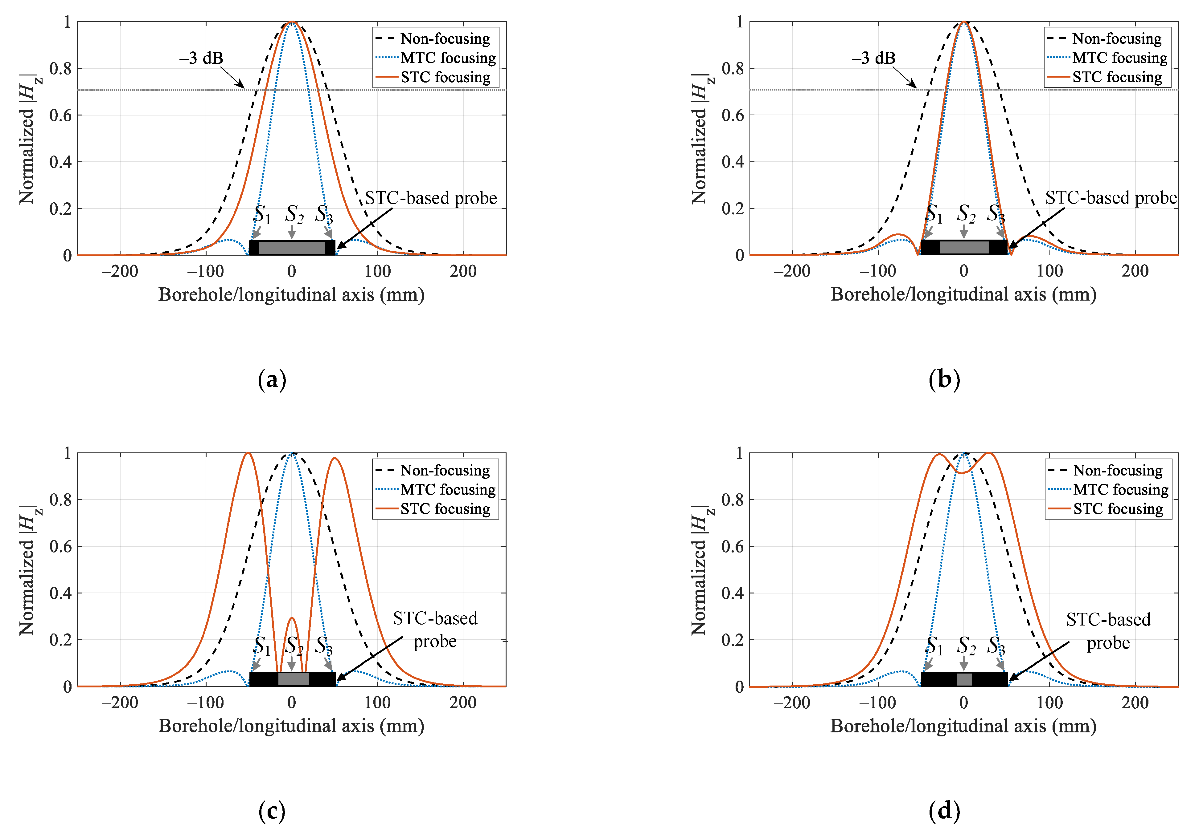
3.1. Magnetic Focusing

We used the model of the PEC system presented in Section 2 to design the proposed STC for MF in downhole environments. Figure 2 compares the structures of the traditional MTCs and the proposed STC. Both are able to focus a synthesized magnetic field more narrowly on a certain area. As shown in Figure 2a, when MTCs send the same current I1 simultaneously, a non-focused magnetic field is excited. MTCs can control the vector of the magnetic field (or transmitting currents with I1, I2, I3, I4, and I5) to achieve MF. However, MTCs not only require more transmitting electrical circuits, but also require the H-bridges and control signals to be almost the same to ensure consistency when the magnetic field is turned on and off; otherwise, large errors can be introduced. Figure 2b shows the proposed STC, which combines the MTCs into a single coil with multiple sections having different winding directions and number of turns to adjust the magnetic field distribution. Specifically, the STC comprises multiple transmitters, each defined as a section. The five sections are connected together, and each section has a different winding direction and number of turns.
The sections of the STC can be divided into two types according to the winding direction: the P-sections have the same winding direction as the middle section, and the N-sections have the opposite winding direction of the middle section. If the total number of turns of the STC is M, then the magnetic field can be expressed as the sum of the fields of each transmitting coil turn:
H ¯ ( z t , t , r , z ) = m = 1 M α m H ( z t m , t , r , z )
where ztm is the position of the mth turn. αm is a coefficient related to the winding direction of the mth turn coil and can be expressed as:
α m = 1 m th   turn   coil P - Section 1 m th   turn   coil N - Section
By stacking αm to form a vector, we obtain:
α = α 1 α 2 α M
The winding parameters of the STC can be expressed by α. Different magnetic field distributions can be achieved by designing the vector α. Let the number of STC sections be K, and the number of turns for each section be nk. The two adjacent sections have opposite winding directions. Therefore, α of the five-section STC shown in Figure 2b can be written as:
α = 1 1 n 1 1 1 n 2 1 1 n 3 1 1 n 4 1 1 n 5
Suppose that Sk represents the kth section for a five-section STC, where S1, S3, and S5 are P-sections, and S2 and S4 are N-sections. To focus the magnetic field on the longitudinal center of the probe, the proposed STC adopts a central-symmetry structure. If the number of sections K is odd, and symmetrical sections have the same number of turns (e.g., n1 = n5 and n2 = n4 for a five-section STC), then the number of turns of section k is equal to the number of turns of section K + 1 − k:
n k = n K + 1 k
Because K is an odd number, the central section is the (K + 1)/2-th section. When K changes, the sequence number for P-sections also changes. For example, S2 is a P-section for a three-section STC while S1, S3, and S5 are P-sections for a five-section STC. The P-sections of STCs with different sequence numbers can be expressed as follows:
P - sections = S 2 ,   S 4 ,     ,   S K + 1 / 2 ,     ,   S K 1 K = 3 , 7 , 11 , S 1 ,   S 3 ,     ,   S K + 1 / 2 ,     ,   S K K = 5 , 9 , 13 ,
Similar to MTCs, which achieve MF by controlling the magnitude and direction of the current in each element of a multi-coil array, the STC controls the magnetic field distribution according to the winding direction and number of turns in each section. Note that the STC is adjusted by the number of turns in each section. In contrast, the MTC is adjusted by the transmitting current, which offers a finer resolution. However, the STC is a single transmitter and requires a simplified single electrical circuit to realize MF, which is more suitable for harsh downhole environments with limited space.

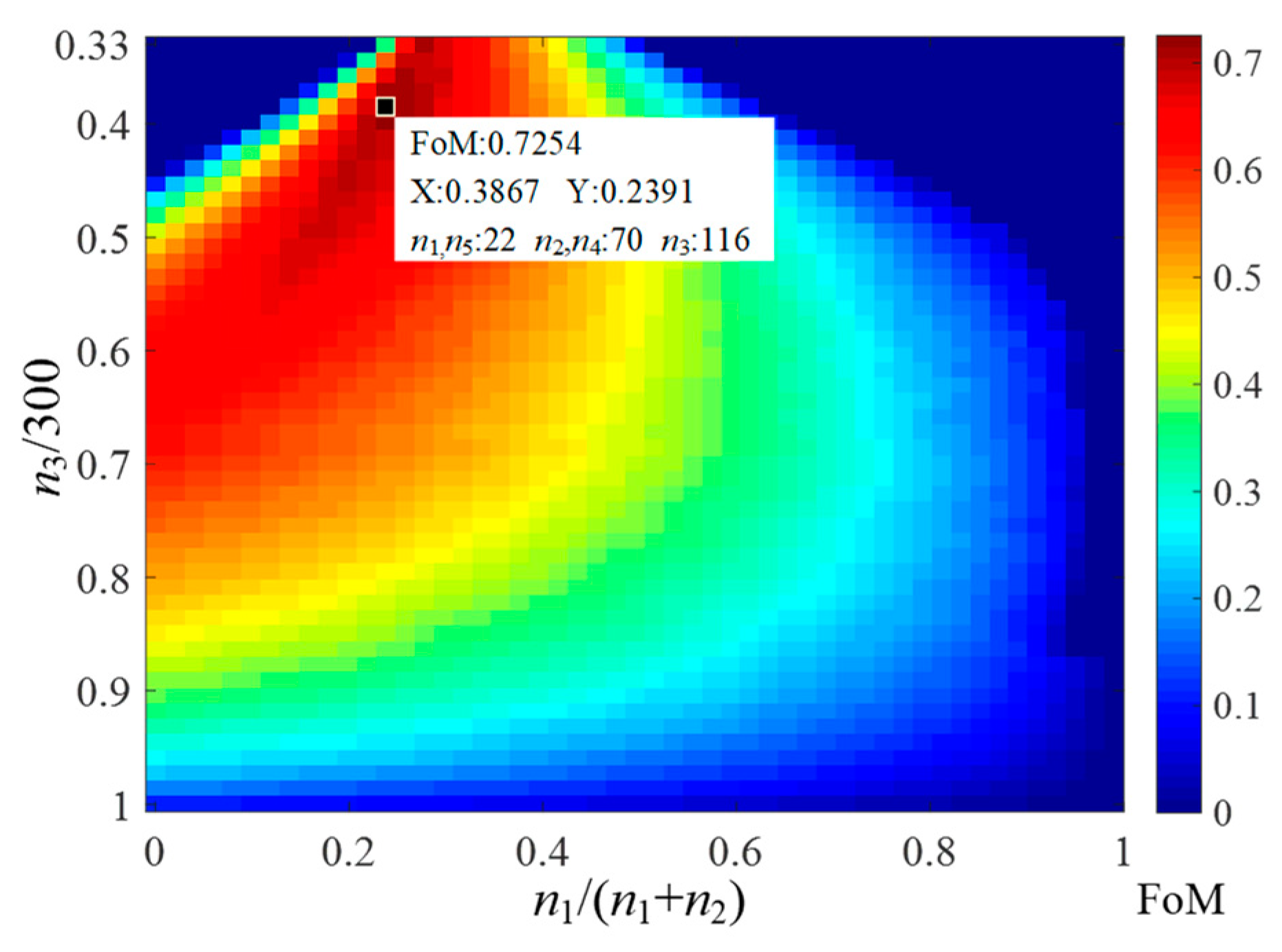
3.2. Optimization of the STC Parameters Using FoM
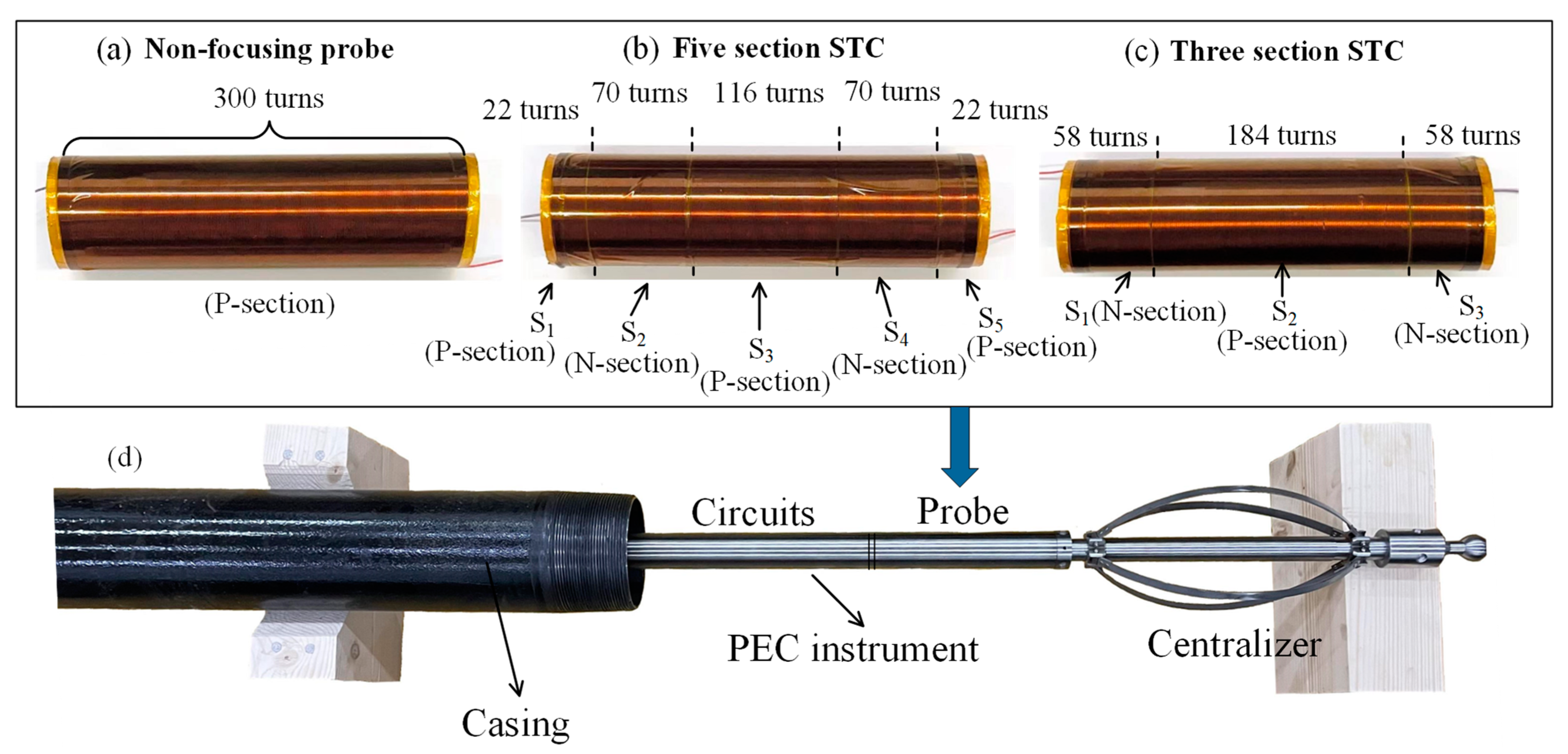
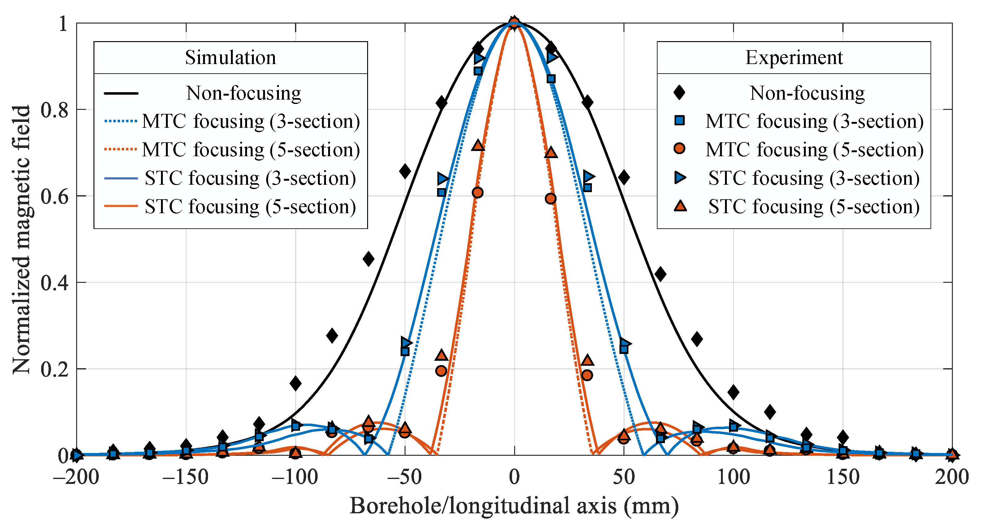
In order to optimize the STC parameters, we made a simulation to analyze the MF performance using the STC, MTC, and no-MF. Figure 3 shows the simulation of the longitudinal component of the magnetic field Hz with different winding schemes using the magnetic module of COMSOL 6.0. A standard 5 in casing was used with a wall thickness of 7.52 mm and inner radius r = 55.98 mm, where t = 0 corresponds to the time when the electrical field was turned off. A three-section STC with 300 turns in total was considered. The radius and wire diameter of the transmitting coils were 12 and 0.33 mm, respectively. The second section (S2) of the STC was a P-section (with a clockwise winding direction), and S1 and S3 were N-sections (with an anticlockwise winding direction) with the same number of turns (n1 = n3). The proportions for the P- and N-sections of the STC are represented by gray and black rectangular blocks, respectively. The longitudinal distribution of the magnetic field along the inner wall of the casing was simulated when n2 = 240 (80% of the total number of turns), 180 (60%), 120 (40%), and 60 (20%). The no-MF and MTC-based MF [17] cases are shown for comparison. The simulation clearly showed that the magnetic field distribution can be changed according to the winding direction of the STC. The MTCs were set to a total number of 300 turns; although the STC had almost the same performance as the MTC-based MF, there should be some performance loss because the MTCs can adjust the transmitting current more finely in theory. To analyze the MF performance, we followed the lead of Tsukada et al. [14] and defined the main lobe width as the distance between the two nearest intersections of the −3 dB line and the curves. Figure 3a shows that the STC obtained a narrower main lobe than the no-MF case when n2 = 240. As n2 was decreased, the main lobe became much narrower, but side lobes appeared, as shown in Figure 3b. At n2 = 120, the height of the side lobe exceeded that of the main lobe, as shown in Figure 3c. At n2 = 60, the main lobe became wider than that of the no-MF case and was even more deformed, as shown in Figure 3d. Therefore, the proposed STC can obtain a narrower main lobe than the no-MF case, but the appropriate winding parameters need to be determined.
Similar to Kim et al. [15], we defined an FoM to evaluate the MF performance. We then determined the optimal STC design according to the combination of winding parameters that realized the largest FoM. The MF performance is related to the width of the main lobe and height of the side lobe. The ratios of the side lobe height, hs, and reduction in the main lobe width, wr, can be defined as follows:
h s = h side   lobe h main   lobe
w r = w non - focusing w focusing w non - focusing
where h denotes the height of the main lobe or side lobe, and w denotes the width of the main lobe in the no-MF, MTC-based MF, or STC-based MF cases. The MF performance is optimized by decreasing hs and increasing wr. Therefore, the following FoM was defined:
FoM = w r × 1 h s
where a square root is applied to wr to increase its contribution to the FoM because this parameter directly affects the longitudinal distribution of the magnetic field. Note that when the main lobe width is widened (i.e., wr is negative, as shown in Figure 3d), the MF performance is poor. This was outside the scope of this study, and the FoM was set to zero in this case. Thus, the optimal design of the STC can be found by determining the number of sections and total turns according to the winding process and instrument space, as well as a suitable combination of winding parameters.
In order to clarify the design procedure, we can use a three-section STC as an example. Figure 4 shows the values of the FoM, wr, and hs for different designs using the same simulation parameters shown in Figure 3, where the horizontal axis denotes the variation of the ratio of n2 to total turns.
It can be observed from Figure 4 that decreasing the ratio of n2 to total turns increased wr and hs, which decreased the main lobe width and increased the side lobe height. This is consistent with the results shown in Figure 3. In order to optimize the MF performance of the proposed STC, we chose to use the parameters corresponding to the maximum FoM that can be achieved, where FoM = 0.6294 and n2/300 = 0.613 as shown in Figure 4. As a result, the optimal design parameters of the three-section STC can be acquired, since n1 = n3 (n2 = 184, n1 = n3 = 58 herein). Similar to the three-section case, the case with more sections can also be extended. It should be noted that the maximum FoM will correspond to different section schemes and the relationship among the coil turns in each section.

4. Experiments

For further validation, we performed simulations and experiments using the proposed STC, where the conditions in simulations and experiments were the same. Figure 5 shows the longitudinal magnetic field distribution of the STC using the optimal design in Section 4 at different inner casing radii and times. As shown in Figure 5a, the longitudinal magnetic field distribution of the STC had a narrow main lobe and a short side lobe at {r = 55.98 mm, t = 0 ms}. The magnetic field distribution differed with the time and radii. Figure 5b–d compare the performances of the no-MF case, MTF-based MF, and STC-based MF at {r = 55.98 mm (inner radius of the casing pipe), t = 10 ms}, {r = 59.74 mm (center of wall of the casing pipe), t = 0 ms}, and {r = 63.5 mm (outer radius of the casing pipe), t = 0 ms}, respectively. The designed FoM can be used to select appropriate winding parameters for the STC and optimize the MF performance to approach that of the ideal MTC-based MF. Comparing with the no-MF case, the longitudinal magnetic field distribution at other radii and observation times can also be focused.
Without loss of a generality, we further simulated the FoM in a five-section case. Figure 6 shows the MF performance of the five-section STC. The total number of turns was set to 300, and the other parameters were the same as those shown in Figure 4. As shown in Equations (8) and (9), S1, S3, and S5 were P-sections, S2 and S4 were N-sections, and n1 = n5 and n2 = n4. Compared with the three-section STC in Figure 4, the five-section STC had a more complex design, and its parameters were related to the coil turns of multiple sections; thus, two uncorrelated factors, n3/300 and n1/(n1 + n2), were used to represent the winding parameters of the five-section STC in Figure 6.
From Figure 6, we can conclude that the MF performance was closely related to the probe design. The maximum FoM value of the five-section STC (FoM = 0.7254) was obtained at n3/300 = 0.3867 and n1/(n1 + n2) = 0.2391 (n3 = 116, n2 = n4 = 70, n1 = n5 = 22). The above winding scheme with the optimal FoM was used to design the structures of the three- and five-section STCs, as shown in Figure 7, in which the PEC inspection system used for the experimental prototype was also included.
In Figure 7, the no-MF probe is also shown for comparison. All probes had 300 turns in total. For the three-section STC, S1–3 had 58, 184, and 58 turns, respectively; while for the five-section STC, S1–5 had 22, 70, 116, 70, and 22 turns, respectively. In our experiment, an observation array with 25 giant magnetoresistance (GMR) sensors (AAH002-02 from NVE Corporation, Minneapolis, MN, USA) was used to measure the longitudinal magnetic field on the inner wall of the casing.
Figure 8 shows the normalized magnetic field of the no-MF, MTC-based MF, and STC-based MF cases with three and five sections in the experiment and simulation. The experimental and simulation conditions were identical.
As shown in Figure 8, the experimental results for the no-MF, MTC-based MF, and STC-based MF cases showed good agreement with the simulation results. The error can be attributed to the inductance error of the additional inductor [15] and differences in the coil geometry. Additionally, the main lobe of the STC was significantly narrower than the no-MF and approximate to that of the MTC for both the three-section and five-section STCs; as the number of sections in STC increases, the main lobe becomes much narrower. Although the proposed STC can realize MF by narrowing the main lobe, the overall magnetic field intensity is reduced because the N-sections excite the magnetic field in the opposite direction. In other words, the STC is a tradeoff that sacrifices magnetic field intensity for a narrower main lobe.
To clarify the tradeoff relationship, we can use the peak value of the main lobe pm to characterize the total magnetic field intensity. Figure 9 compares the maximum FoMs that can be achieved by STC- and MTC-based probes and their corresponding wr values. The maximum current of the transmitting coil was set to 1 A, and the total number of turns was 300 for all probes. The three- and five-section STCs were designed according to the optimal parameters given in Figure 4 and Figure 6, respectively.
From Figure 9, it can be observed that increasing pm clearly decreased the MF effect with respect to FoM and wr. Note that pm was a constant value to ensure that the eddy current field was sufficiently large enough to meet detection range and SNR requirements. Setting pm higher is not required because the casing is not very large, and setting pm lower would not result in an acceptable SNR. Specifically, when pm = 0, the STC- and MTC-based probes achieved their maximum FoM values regardless of the magnetic field intensity. The FoM and wr values of both STCs nearly reached that of the MTC. In addition, the FoM and wr values of both the three- and five-section STCs remained unchanged, with increasing pm until pm = 0.289 × 10⁻³ T and 1.592 × 10⁻³ T, respectively. The five-section STC had a higher FoM than the three-section STC at the cost of a reduced magnetic field intensity. However, when pm > 1.592 × 10⁻³ T, the two STCs had very similar FoMs because most of the coil turns were allocated to the middle section. In most cases shown in Figure 9, the FoMs of the STC nearly reached that of the MTC-based probe. At pm = 2.75 × 10⁻³ T, the FoMs of the STCs and MTC-based probes were equal because the N-section had zero turns to maximize pm. In general, the MF performance of STC with a single transmitter and a simplified single electrical circuit was close to that of the MTC, which can reach the needed sensitivity for the detection of submillimeter defects, and is more suitable for harsh downhole environments with limited space.

5. Conclusions

A novel STC is proposed comprising connected sections with different winding directions and number of turns to realize a PEC system with MF for downhole casing inspection. The proposed design simplifies the electrical circuit and is more suitable for narrow downhole environments. A model of the PEC system was used to theoretically derive the transmitting magnetic field, and an FoM was constructed to evaluate the MF performance and optimize the winding parameters of the STC. The simulation and experimental results for a standardized oil well casing revealed that the proposed STC is effective at realizing MF.

Author Contributions

Conceptualization, C.L.; methodology, B.D.; software, C.L.; validation, Y.Z.; formal analysis, J.D.; investigation, L.Y.; resources, B.D.; data curation, L.Y.; writing—original draft preparation, L.Y.; writing—review and editing, L.Y.; visualization, R.D.; supervision, Y.Z.; project administration, R.D.; funding acquisition, B.D. All authors have read and agreed to the published version of the manuscript.

Funding

This work was supported in part by the National Natural Science Foundation of China under Grant 51974250 and Grant 41874158, in part by the Youth Science and Technology Nova Project in Shaanxi Province, China, under Grant 2020KJXX-018, and in part by the Postgraduate Innovation and Practical Ability Training Program of Xi’an Shiyou University under Grant YCS22111001.

Institutional Review Board Statement

Not applicable.

Informed Consent Statement

Not applicable.

Data Availability Statement

All the details of this work, including data and algorithm codes, are available by contacting the corresponding author: [email protected].

Acknowledgments

The authors would like to thank the reviewers for their helpful suggestions, which have considerably improved the quality of the manuscript.

Conflicts of Interest

The authors declare no conflict of interest.

References

  1. Malekmohammadi, H.; Migali, A.; Laureti, S.; Ricci, M. A Pulsed Eddy Current Testing Sensor Made of Low-Cost Off-the-Shelf Components: Overview and Application to Pseudo-Noise Excitation. IEEE Sens. J. 2021, 21, 23578–23587. [Google Scholar] [CrossRef]
  2. Meng, T.; Tao, Y.; Chen, Z.; Avila, J.R.S.; Ran, Q.; Shao, Y.; Huang, R.; Xie, Y.; Zhao, Q.; Zhang, Z.; et al. Depth Evaluation for Metal Surface Defects by Eddy Current Testing Using Deep Residual Convolutional Neural Networks. IEEE Trans. Instrum. Meas. 2021, 70, 1–13. [Google Scholar] [CrossRef]
  3. Yan, B.; Li, Y.; Liu, Z.; Ren, S.; Chen, Z.; Lu, X.; Abidin, I.M.Z. Pulse-Modulation Eddy Current Imaging for 3D Profile Reconstruction of Subsurface Corrosion in Metallic Structures of Aviation. IEEE Sens. J. 2021, 21, 28087–28096. [Google Scholar] [CrossRef]
  4. Niu, C.; Wang, L.; Wang, Y.; Zhai, Y.; Qu, H.; Liu, Y.; Wang, Q. Numerical Analysis of Eddy Current Induced by z-Gradient Coil in a Superconducting MRI Magnet. IEEE Trans. Appl. Supercond. 2020, 30, 1–6. [Google Scholar] [CrossRef]
  5. Xiao, Q.; Feng, J.; Xu, Z.; Zhang, H. Receiver Signal Analysis on Geometry and Excitation Parameters of Remote Field Eddy Current Probe. IEEE Trans. Ind. Electron. 2021, 69, 3088–3098. [Google Scholar] [CrossRef]
  6. Suresh, V.; Abudhahir, A.; Daniel, J. Characterization of Defects on Ferromagnetic Tubes Using Magnetic Flux Leakage. IEEE Trans. Magn. 2019, 55, 1–10. [Google Scholar] [CrossRef]
  7. Wang, Y.; Nie, Y.; Qi, P.; Zhang, N.; Ye, C. Inspection of Defect Under Thick Insulation Based on Magnetic Imaging with TMR Array Sensors. IEEE Trans. Magn. 2021, 58, 1–10. [Google Scholar] [CrossRef]
  8. Liu, C.; Dang, B.; Wang, H.; Shen, X.; Yang, L.; Ren, Z.; Dang, R.; Kang, Y.; Sun, B. Multiple-Transmit Focusing for the Nondestructive Testing of Downhole Casings Based on Borehole Transient Electromagnetic Systems. IEEE Access 2020, 8, 210978–210987. [Google Scholar] [CrossRef]
  9. Fu, Y.; Yu, R.; Peng, X.; Ren, S. Investigation of casing inspection through tubing with pulsed eddy current. Nondestruct. Test. Eval. 2012, 27, 353–374. [Google Scholar] [CrossRef]
  10. Wu, T.; Bowler, J.; Theodoulidis, T.P.; Th, T. Eddy Current Induction by a Coil Whose Axis is Perpendicular to that of a Tube. IEEE Trans. Magn. 2017, 53, 6201709. [Google Scholar] [CrossRef]
  11. Zhou, H.; Hou, K.; Pan, H.; Chen, J.; Wang, Q. Study on the Optimization of Eddy Current Testing Coil and the Defect Detection Sensitivity. Press. Vessel. Technol. Prep. Future 2015, 130, 1649–1657. [Google Scholar] [CrossRef] [Green Version]
  12. Dang, B.; Yang, L.; Du, N.; Liu, C.; Dang, R.; Wang, B.; Xie, Y. Auxiliary Sensor-Based Borehole Transient Electromagnetic System for the Nondestructive Inspection of Multipipe Strings. Sensors 2017, 17, 1836. [Google Scholar] [CrossRef] [PubMed]
  13. Yang, C.; Gao, B.; Ma, Q.; Xie, L.; Tian, G.Y.; Yin, Y. Multi-Layer Magnetic Focusing Sensor Structure for Pulsed Remote Field Eddy Current. IEEE Sens. J. 2018, 19, 2490–2499. [Google Scholar] [CrossRef] [Green Version]
  14. Tsukada, K.; Hirata, T.; Goda, Y.; Sakai, K.; Kiwa, T. Hybrid Magnetic Sensor Combined With a Tunnel Magnetoresistive Sensor and High-Temperature Superconducting Magnetic-Field-Focusing Plates. IEEE Trans. Appl. Supercond. 2018, 29, 8800405. [Google Scholar] [CrossRef]
  15. Kim, J.H.; Choi, B.; Kim, H.R.; Rim, C.-T.; Kim, Y.-S. Single-Variable-Input Active Sidelobe Suppression Method for Synthesized Magnetic Field Focusing Technology and Its Optimization. IEEE Trans. Ind. Electron. 2019, 67, 9813–9823. [Google Scholar] [CrossRef]
  16. Kim, J.H.; Choi, B.H.; Kim, H.R.; Rim, C.T. 2-D synthesized magnetic field focusing technology With loop coils distributed in a rectangular formation. IEEE Trans. Ind. Electron. 2019, 66, 5558–5566. [Google Scholar] [CrossRef]
  17. Liu, C.; Dang, B.; Wang, H.Y.; Yang, L.; Dang, J.; Shen, X.; Dang, R. Synthesised magnetic field focusing for the non-destructive testing of oil and gas well casing pipes using pulsed eddy-current array. IEEE Trans. Magn. 2022. [Google Scholar] [CrossRef]
  18. Cubero, D.; Marmugi, L.; Renzoni, F. Exploring the limits of magnetic field focusing: Simple planar geometries. Results Phys. 2020, 19, 103562. [Google Scholar] [CrossRef]
  19. Tanaka, H.; Iizuka, H. Kilohertz Magnetic Field Focusing Behavior of a Single-Defect Loop Array Characterized by Curl of the Current Distribution With Delta Function. IEEE Antennas Wirel. Propag. Lett. 2012, 11, 1088–1091. [Google Scholar] [CrossRef]
  20. Mohammed, A.I.; Oyeneyin, B.; Atchison, B.; Njuguna, J. Casing structural integrity and failure modes in a range of well types—A review. J. Nat. Gas Sci. Eng. 2019, 68, 102898. [Google Scholar] [CrossRef]
  21. Wu, S.N.; Zhang, L.B.; Fan, J.C.; Zhang, X.M.; Zhou, Y.F.; Wang, D.G. Prediction analysis of downhole tubing leakage location for offshore gas production wells (in English). Measurement 2018, 127, 546–553. [Google Scholar] [CrossRef]
  22. Ulapane, N.; Thiyagarajan, K.; Miro, J.V.; Kodagoda, S. Surface Representation of Pulsed Eddy Current Sensor Signals for Improved Ferromagnetic Material Thickness Quantification. IEEE Sens. J. 2020, 21, 5413–5422. [Google Scholar] [CrossRef]
  23. Kaufman, A.A.; Yu, A. Dashevsky. In Principles of Induction Logging; Elsevier: Amsterdam, The Netherlands, 2003. [Google Scholar]
  24. Li, J.H.; Farquharson, C.G.; Hu, X.Y. Three effective inverse Laplace transform algorithms for computing time domain electromagnetic responses (in English). Geophysics 2016, 81, E113–E128. [Google Scholar] [CrossRef]
Figure 1. PEC system for borehole casing inspection.
Applsci 12 07695 g001
Figure 2. Structural comparison: (a) MTCs and (b) the proposed STC.
Applsci 12 07695 g002
Figure 3. Longitudinal magnetic field distribution at r = 55.98 mm and t = 0 of the three-section STC: (a) n2 = 240, (b) n2 = 180, (c) n2 = 120, and (d) n2 = 60.
Applsci 12 07695 g003
Figure 4. MF performance of the proposed STC with different winding parameters.
Applsci 12 07695 g004
Figure 5. Longitudinal magnetic field distributions with no-MF, MTC-based MF, and STC-based MF: (a) r = 55.98 mm, t = 0 ms; (b) r = 55.98 mm, t = 10 ms; (c) r = 59.74 mm, t = 0 ms; and (d) r = 63.5 mm, t = 0 ms.
Applsci 12 07695 g005
Figure 6. Variation in MF performance of the five-section STC with different winding parameters.
Applsci 12 07695 g006
Figure 7. Probe structures and PEC inspection system for the experiments: (a) non-focusing probe structure; (b) five-section STC probe; (c) three-section STC probe; and (d) the PEC inspection system.
Applsci 12 07695 g007
Figure 8. Experimental and simulation results for MF with the five-section STC.
Applsci 12 07695 g008
Figure 9. FoMs of the MTC and STC at different pm values.
Applsci 12 07695 g009
Publisher’s Note: MDPI stays neutral with regard to jurisdictional claims in published maps and institutional affiliations.

