Article

Design Optimization and Electromagnetic Performance Analysis of an Axial-Flux Permanent Magnet Brushless DC Motor with Unequal-Thickness Magnets

Huaiyin Institute of Technology, Faculty of Automation, Huai’an 223002, China
*
Author to whom correspondence should be addressed.
Appl. Sci. 2022, 12(15), 7863; https://doi.org/10.3390/app12157863
Submission received: 28 June 2022 / Revised: 2 August 2022 / Accepted: 3 August 2022 / Published: 5 August 2022

Abstract

:
To improve electromagnetic performance, an axial-flux permanent magnet brushless DC motor (AFPMBLDCM) with unequal-thickness arc permanent magnets is proposed in this paper. Firstly, the structure and magnetic circuit of the AFPMBLDCM with unequal-thickness arc permanent magnets were designed. Then, the mathematical models and design method of the main parameters were derived. According to the rated power and rated speed, the main parameters were further designed, and the analytical model was established by using Maxwell 3D. The air-gap flux density, back electromotive force (EMF) and torque under no-load and load conditions were calculated and analyzed to verify the validity of the model and design. Finally, based on a parameter scanning optimization method, the effects of the permanent magnet thickness, pole arc coefficient and permanent magnet radius on cogging torque were analyzed. The optimized parameters of the AFPMBLDCM with unequal-thickness arc permanent magnets were obtained. The results show that the sinusoidal degree of the air-gap magnetic field is improved, and the maximum torque ripple of the AFPMBLDCM is reduced to 2.92%.

1. Introduction

The axial-flux permanent magnet brushless DC motor (AFPMBLDCM) has received increasing attention due to its compact structure, small axial size, light weight, high power density ratio and other properties [1,2,3]. At present, the applications of the AFPMBLDCM at home and abroad are mainly concentrated in high-tech industries and practical application fields [4,5,6]. Especially in the case of motor axial size limitations, such as flywheel energy storage [7], new energy vehicles [8,9], household appliances [10,11], electric bicycles [12,13] and other situations [14,15], it has more advantages than the radial motor [16,17,18]. However, this kind of motor still has low efficiency [19], large torque ripple [20], low utilization of permanent magnets and other issues to be solved.
The AFPMBLDCM has a long history of development and wide application prospects. Many scholars have carried out in-depth research on motor operation efficiency [21], operation reliability [22], power density [23] and other aspects [24]. In order to improve motor efficiency, in [24], a novel multi-layer PCB stator structure was proposed to make the phase windings more evenly distributed. The designed motor was expected to generate an average torque of 0.02 N m at 30,000 r/min with an efficiency of 94%. However, due to the large air-gap length, its permanent magnet consumption is more than that of the traditional magnet with an iron core structure, and the manufacturing cost of the proposed motor is higher. In order to improve the fault tolerance, a detached winding configuration was proposed to replace the traditional winding for asymmetric six-phase double-stator axial-flux permanent magnet machines [25]. Furthermore, rotor eddy current losses could be reduced by 25% and 70% under normal and fault-tolerant operating conditions, respectively, without sacrificing torque output. A topological structure of a multi-disc coreless axial-flux permanent-magnet synchronous machine was proposed [26]. The magnetic circuit and air-gap flux intensity were analyzed to improve the stable operation of the motor. Based on the finite element method, the relationship between the air-gap flux density and the parameters was clarified. Furthermore, the winding structure and power driver topology with fault tolerance were presented. To improve the torque density, permanent magnets were placed between the adjacent rotor teeth with a switched-flux feature. Based on the three-dimensional finite element optimization method, the loss and efficiency were about 60.7 W and 90.8%, respectively, at the rated speed on a rated road [27]. In [28], the arc-shaped permanent magnet was proposed. It has notches so that it produces a discrete skew effect, which reduces the cogging torque and torque ripple. Compared with the radial-flux permanent magnet brushless DC motor, the AFPMBLDCM has many advantages, such as high power density, high efficiency, a high torque/current ratio and flat shape. The AFPMBLDCM can be classified according to the number and relative positions of stators and rotors. In particular, the torque quality assessment of the AFPMBLDCM is a challenging task, as torque ripple should also be considered along with torque density. Thus, torque ripple and its reduction are currently of research interest to many researchers [29]. As is well known, the main sources of torque ripple are cogging torque [30], distorted stator current [31] and counter-EMF waveforms [32]. An effective method to reduce cogging torque is the optimization design of motor parameters based on the finite element method [33,34,35].
In this study, an AFPMBLDCM with arc-shaped permanent magnets was designed. It is characterized by a sinusoidal air-gap magnetic field and low cogging torque ripple. Firstly, the topology structure of the AFPMBLDCM with unequal-thickness arc permanent magnets was designed. The mathematical models and design of the main parameters were derived. According to the rated power and rated speed, the analytical model was established by using Maxwell 3D. The air-gap flux density, back electromotive force (EMF) and torque were calculated and analyzed to verify the model and design. Finally, based on the parameter scanning optimization method, the effects of the permanent magnet thickness, pole arc coefficient and permanent magnet radius on cogging torque were analyzed. The optimized parameters of the AFPMBLDCM with unequal-thickness arc permanent magnets were obtained. The results show that the sinusoidal degree of the air-gap magnetic field is improved, and the maximum torque ripple of the AFPMBLDCM is reduced to 2.92%.

2. Structure of AFPMBLDCM

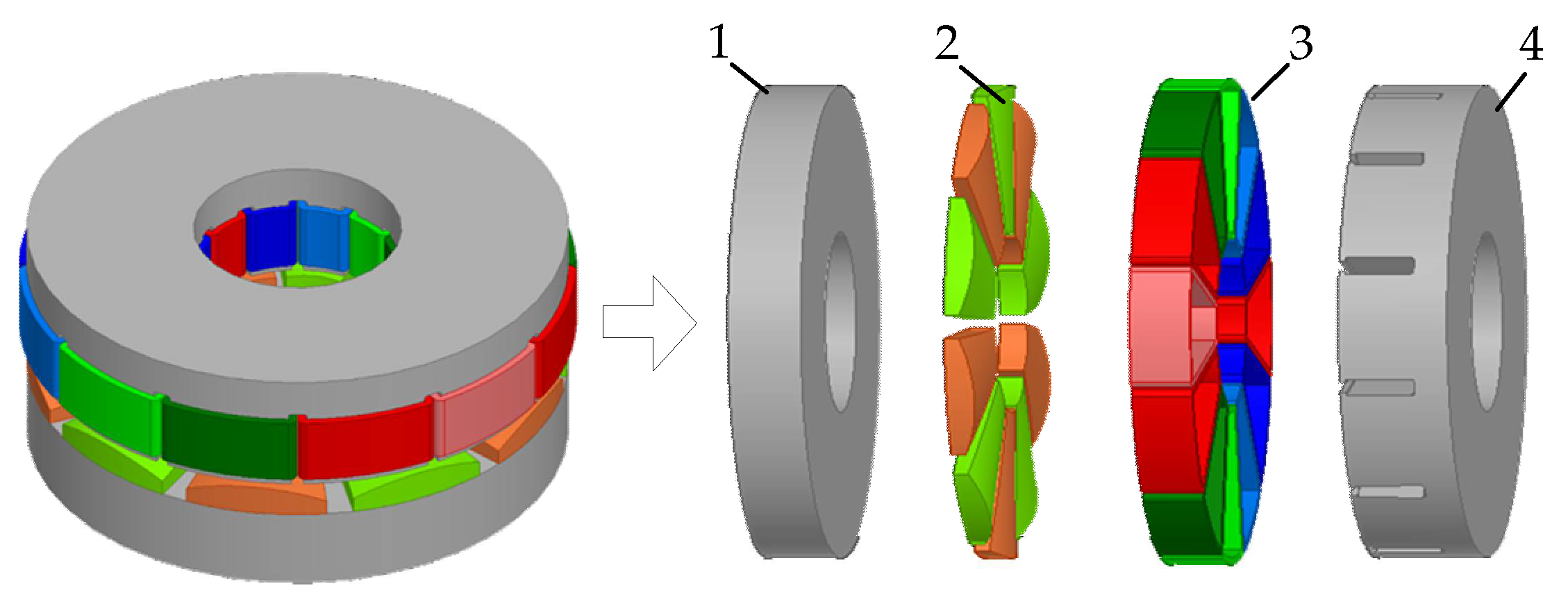
2.1. Topology of AFPMBLDCM

The AFPMBLDCM has a variety of topologies. These mainly include the single-stator and single-rotor structure, double-stator and single-rotor structure, double-rotor and single-stator structure, and multi-disc structure. In addition, it also includes slotted stator and non-slotted stator structures. Because the AFPMBLDCM with a single rotor and a single stator has a greater advantage in axial size, it is favorable for flat mounts and thin drives. Furthermore, compared with the non-slotted stator AFPMBLDCM, the slotted stator AFPMBLDCM can reduce the equivalent air-gap length and is convenient for winding installation, and it can further reduce the number of permanent magnets. Thus, the AFPMBLDCM described in this paper has a slotted single-stator and single-rotor structure, as shown in Figure 1.
Figure 2 shows the main magnetic circuit of the AFPMBLDCM, in which the leakage flux is ignored. The main flux starts from the N-pole of the arc-shaped permanent magnet, passes through the air gap, the stator core, and rotor back iron and returns to the S-pole of the adjacent permanent magnet to form a closed path.

2.2. Unequal-Thickness Arc-Shaped Permanent Magnets

The AFPMBLDCM contains surface-mounted permanent magnets. The permanent magnet is installed on the back iron of the rotor core in N S alternating mode. Instead of traditional permanent magnets, arc-shaped permanent magnets are adopted, resulting in unequal-thickness air gaps. The sectional view of the permanent magnet is shown in Figure 3. Numbers “1”, “2”, “3”, “4” and “5” represent the upper arc surface, the bottom surface, the radius of the upper arc surface, the left side and the right side, respectively. The locations of “4” and “5” are perpendicular to “2”. The initial radius of the upper arc surface of the unequal-thickness permanent magnets described in this paper is 19 mm, which was optimized according to the optimal target, as described later.

3. Main Parameter of AFPMBLDCM

3.1. Number of Poles/Slots

The selection of slot/pole numbers has a great influence on the performance of the AFPMBLDCM. The number of stator slots q and the number of permanent magnet poles p should agree with the following equations:
q = k · q 0 p = k · p 0
where k is the greatest common factor of q and p; q0 is a multiple of 3, thus ensuring the symmetry of three-phase windings; p0 is not a multiple of 3; and q0 and p0 are prime numbers to each other.
The more pole pairs of the motor, the higher the flux leakage and the lower the utilization rate of the permanent magnets. Therefore, the number of poles of a low-power AFPMBLDCM is 8~14 poles. The number of slots is close to the number of poles, which is conducive to improving the performance of the motor. The structures of 8 poles and 9 slots and the structures of 10 poles and 9 slots have a high harmonic component of MMF and large eddy current loss in the rotor. Therefore, the number of poles p = 10, and the number of slots q = 12. The internal and outer diameter polar arc coefficients of the permanent magnet described in this paper are the same. When the number of poles p is determined, the polar arc coefficient should be reasonably selected. The results show that the sinusoidal degree of the air-gap magnetic field is the best when the polar arc coefficient αi is 0.77. Thus, the initial value is 0.8 for the polar arc coefficient in this paper, which was also optimized according to the optimal target, as discussed later.

3.2. Power and Torque

The stator windings of the AFPMBLDCM are distributed. According to the charge characteristics, the electric load at the outer diameter of the conductor is the minimum value, and the electric load at the inner diameter of the conductor is the maximum value. Therefore, the conductor electrical load at the average radius is considered for calculations. The average electric load Aav is
A a v = I 1 N x π ( R i + R o )
The phase current I1 of the AFPMBLDCM is
I 1 = A a v π ( R i + R o ) N x
When the rated speed is n, the output electromagnetic power Pe of the AFPMBLDCM is
P e = 3 E 1 I 1 = 1 5 n π 2 K x B δ A a v R i 3 ( β + 1 ) 2 ( β - 1 )
where β is the ratio between the inner diameter and outer diameter.
According to Aav and I1, the electromagnetic torque Te of the AFPMBLDCM is
T e = 3 4 π K x α i B δ A a v ( β + 1 ) 2 ( β - 1 )

3.3. Size of AFPMBLDCM Structure

According to Equation (4), the outer diameter of the AFPMBLDCM can be obtained as
D o = 40 β 3 P e m π 2 K x n α i B δ a v A a v ( β + 1 ) 2 ( β - 1 ) 3
D i = D o β

3.4. No-Load Back EMF

When the AFPMBLDCM is running under no-load conditions, the permanent magnet rotates with the rotor. It creates a constantly changing magnetic field in the air gap. The windings generate an induced electromotive force by cutting magnetic field lines. The main air-gap flux Φδ of the AFPMBLDCM is distributed along the axial direction, and the effective length is distributed along the radial direction. Therefore, the air-gap magnetic density Bδ(θ) at the average radius was selected for equivalent calculations. As shown in Figure 4, the position of the conductor on magnetic steel is indicated by the radius c and polar angle θ.
The distance between the inner and outer radii of the winding Ri and Ro can be any length dc. When the winding conductor rotates at an angle dθ at Ω angular velocity, the average induced electromotive force E1 generated by a single winding conductor can be obtained as follows.
E 1 = Ω R i R o B δ ( θ ) c d c = 1 2 Ω B δ a v ( R o 2 - R i 2 )
B δ a v = α i B δ
where αi is the polar arc coefficient. Bδav is the average air-gap flux density of the motor at one pole distance.
When the winding coefficient is Kx, the number of turns per phase is Nx. When the number of parallel branches is 1, the induced electromotive force Ex of each phase winding can be written as
E x = N x K x α i Ω B δ ( R o 2 - R i 2 )
If the magnetic pole material, shape, polar arc coefficient, inner diameter and outer diameter of the AFPMBLDCM are determined, the permanent magnet thickness hm is also limited. The thickness of the permanent magnet can be calculated based on the principle of maximum magnetic energy product. According to design experience and the thickness of the permanent magnet, the length of the air gap can be calculated. The initial thickness of the permanent magnet described in this paper is 3.4 mm. The length of the air gap is 0.8 mm. In summary, the design parameters of the AFPMBLDCM can be obtained, as shown in Table 1.

4. Electromagnetic Performance Analysis

According to the basic parameters shown in Table 1, the finite element analysis model of the AFPMBLDCM was established, and its electromagnetic performance was analyzed, including static magnetic field analysis, transient magnetic field analysis and parameter optimization. In order to improve the efficiency of the analysis and solution and save calculation time, the half-equivalent AFPMBLDCM model was established on the premise of ensuring calculation accuracy and the motor’s cyclic symmetry, as shown in Figure 5. In addition, manual meshing, motion boundary setting and master–slave boundary setting were carried out.

4.1. Air-Gap Magnetic Density

The air-gap magnetic field region is the core region of motor energy conversion. Therefore, it is necessary to analyze the distribution of the air-gap magnetic field inside the motor. Generally, the air-gap magnetic density at each diameter is taken as a reference. After post-processing, the air-gap flux density waveform at different radii distributed along the circumferential direction is obtained, as shown in Figure 6.
In Figure 6, we can see that the magnetic density amplitude of the air gap at its innermost diameter is about 0.54 T. The air-gap flux density amplitude at the average radius of the air gap is about 1.06 T. The air-gap magnetic density amplitude at its outermost diameter is about 0.55 T. The air-gap flux density waveforms Bδ are different at different positions. The air-gap flux density amplitudes at the innermost and outermost sides are smaller than those at the average radius. Due to the special structure of the AFPMM, the permanent magnet has an edge effect on both inner and outer diameters, which makes the air-gap magnetic density smaller.

4.2. No-Load Back EMF

The no-load back EMF is the main factor affecting the electromagnetic performance of the AFPMBLDCM. Therefore, at the rated voltage of the AFPMBLDCM, the no-load back EMF amplitude of the three-phase winding was analyzed at a speed of 4800 rpm. Next, phase B was selected for harmonic analysis.
Figure 7 shows that the amplitude of no-load back EMF is about 11.85 V. The waveform is similar to a sine wave and has fine sinusoidal properties.
Figure 8 shows that when the no-load motor runs at rated speed, the no-load back EMF mainly contains third harmonics. The harmonic of no-load back EMF mainly comes from the air-gap flux density distortion caused by stator slotting.

4.3. Load Back EMF

In order to check the load capacity of the AFPMBLDCM at a rated speed of 4800 rpm, rated excitation was applied to the windings. Figure 9 shows the three back EMF waveforms of the AFPMBLDCM when the rated load is added. It can be seen that the back EMF has a nearly sinusoidal distribution under rated load.

4.4. Flux Linkage and Torque

Figure 10 shows the stator winding flux linkage waveform of the AFPMBLDCM with rated load. Figure 11 shows the output torque curve of the AFPMBLDCM running at a speed of 4800 rpm. The average output torque reaches 500.191 mNm, which meets the requirement for a rated torque of 0.50 Nm. The output torque of the AFPMBLDCM is given in Table 2. However, the maximum torque ripple with the combination of permanent magnet thickness, polar arc coefficient and permanent magnet arc radius is as high as 9.07%. Therefore, the optimization of cogging torque must be considered.

5. Optimization of Cogging Torque

Optimetrics, the optimization analysis module provided in Maxwell software, supports parametric analysis. We can define multiple variables and scan these variables to find the optimal parameter fit. The parameter scanning method was used to optimize the cogging torque fluctuation of the AFPMBLDC. The optimization goal is to reduce the cogging torque fluctuation to less than 5%. The three parameter variables subjected to scanning and optimization are shown in Table 3, which are the pole arc coefficient, permanent magnet thickness and permanent magnet arc edge radius.

5.1. Influence of Permanent Magnet Thickness on Cogging Torque

Through parameter scanning and output torque simulation verification, the permanent magnet thickness corresponding to the minimum torque volatility was obtained. Figure 12 shows the relationship between the permanent magnet thickness and torque ripple. When the permanent magnet thickness is 3.8 mm, the corresponding torque volatility is 3.16%. At this point, the cogging torque is the minimum value.

5.2. Influence of Polar Arc Coefficient on Cogging Torque

The polar arc coefficient corresponding to the minimum torque ripple was obtained through parameter scanning and output torque simulation verification. Figure 13 shows the relationship between the polar arc coefficient and torque ripple. When the polar arc coefficient is 0.84, the corresponding torque volatility is 4.28%. At this point, the cogging torque is the minimum value.

5.3. Influence of Arc Radius of Permanent Magnet on Cogging Torque

Through parameter scanning and output torque simulation verification, the value of the permanent magnet arc radius corresponding to the minimum torque volatility was obtained. Figure 14 shows the relationship between the arc radius and torque ripples of the permanent magnet. When the arc radius of the permanent magnet is 21 mm, the corresponding torque volatility is 2.47%. At this point, the cogging torque is at its minimum.

5.4. Optimization Results

After modifying the parameters of the original AFPMBLDCM model, the optimized model was verified by simulation. The simulation results are shown in Figure 15. The output torque parameters are shown in Table 4. The simulation results show that the maximum torque ripple of the AFPMBLDCM is reduced to 2.92% by the parameter scanning optimization method. Compared with Figure 11 and Table 2, we concluded that the optimization method proposed in this paper can effectively reduce the torque ripple of the AFPMBLDCM.

6. Conclusions

In this paper, an AFPMBLDC with unequal-thickness arc-shaped permanent magnets is proposed. We designed the structures of the AFPMBLDC and arc-shaped permanent magnets. Then, according to the given design requirements, the main parameters, such as the number of pole slots, torque, power, dimensions and back EMF, were designed. Furthermore, based on Maxwell 3D, the electromagnetic characteristics of air-gap flux density, back EMF, torque and flux linkage were calculated. The analysis results show that the torque, power, flux linkage and back EMF meet the design requirements, but the torque ripple is large, with a value of 9.07%. Thus, to reduce torque ripple, we set the reduction in cogging torque as the optimization goal and set pole arc coefficient and permanent magnet thickness and permanent magnet arc radius as optimization variables; then, the optimal parameter combination (αi = 0.84; rh = 21 mm; hm = 3.8 mm) was obtained. After optimization, the maximum torque ripple of the AFPMBLDCM was reduced to 2.92% by the parameter scanning optimization method.

Author Contributions

Conceptualization, Q.G.; writing—review and editing, B.W., S.W. and T.Z.; supervision, S.W. and T.Z. All authors have read and agreed to the published version of the manuscript.

Funding

This research received no external funding.

Institutional Review Board Statement

Not applicable.

Informed Consent Statement

Not applicable.

Data Availability Statement

Data are contained within the article.

Conflicts of Interest

The authors declare no conflict of interest.

References

  1. Capponi, F.G.; Donato, D.G.; Caricchi, F. Recent advances in axial-flux permanent-magnet machine technology. IEEE Trans. Ind. Appl. 2012, 48, 2190–2205. [Google Scholar] [CrossRef]
  2. Zhu, G.; Li, L.; Liu, X.; Chen, H.; Jiang, W.; Xue, M.; Li, M. Design optimization of a HTS-modulated PM wind generator. IEEE Trans. Appl. Supercond. 2021, 31, 5204004. [Google Scholar] [CrossRef]
  3. Kappatou, J.; Zalokostas, G.; Spyratos, D. 3-D FEM analysis, prototyping and tests of an axial flux permanent-magnet wind generator. Energies 2017, 10, 1269. [Google Scholar] [CrossRef] [Green Version]
  4. Balachandran, T.; Yoon, A.; Lee, D.; Xiao, J.; Haran, K.S. Ultra-High-Field, High-efficiency superconducting machines for offshore wind Turbines. IEEE Trans. Magn. 2021, 58, 8700805. [Google Scholar]
  5. Rata, M.; Rata, G.; Filote, C.; Raboaca, M.S.; Graur, A.; Afanasov, C.; Felseghi, A.-R. The electrical vehicle simulator for charging station in mode 3 of IEC 61851-1 Standard. Energies 2020, 13, 176. [Google Scholar] [CrossRef] [Green Version]
  6. Kelouaz, M.; Ouazir, Y.; Hadjout, L.; Mezani, S.; Lubin, T.; Berger, K.; Lévêque, J. 3D magnetic field modeling of a new superconducting synchronous machine using reluctance network method. Phys. C Supercond. 2018, 548, 5–13. [Google Scholar] [CrossRef] [Green Version]
  7. Meyyappan, C.; Ravichandran, C.S. Generation of free energy using a compact flywheel. In Proceedings of the International Conference on Electronics and Renewable Systems (ICEARS 2022), Tuticorin, India, 16–18 March 2022; pp. 174–180. [Google Scholar]
  8. Gao, P.; Gu, Y.; Wang, X. The design of a permanent magnet in-wheel motor with dual-stator and dual-field-excitation used in electric vehicles. Energies 2018, 11, 424. [Google Scholar] [CrossRef] [Green Version]
  9. Ahmadi Darmani, M.; Hooshyar, H. Optimal design of axial flux permanent magnet synchronous motor for electric vehicle applications using GA and FEM. J. Electr. Comput. Eng. Innov. 2015, 3, 89–97. [Google Scholar]
  10. Bandarkar, A.W.; Yilmaz, S.; De Abreu-Garcia, J.A. CFD based design of an impeller for a novel integrated motor-compressor system. In Proceedings of the 2019 IEEE Energy Conversion Congress and Exposition (ECCE), Baltimore, MD, USA, 29 September–3 October 2019; pp. 3820–3824. [Google Scholar]
  11. Mohamed, A.H.; Vansompel, H.; Sergeant, P. An integrated modular motor drive with shared cooling for axial flux motor drives. IEEE Trans. Ind. Electron. 2021, 68, 10467–10476. [Google Scholar] [CrossRef]
  12. Lee, C.; Liu, C.; Chau, K. A magnetless axial-flux machine for range-extended electric vehicles. Energies 2014, 7, 1483–1499. [Google Scholar] [CrossRef] [Green Version]
  13. Zhao, J.; Han, Q.; Dai, Y.; Hua, M. Study on the Electromagnetic design and analysis of axial flux permanent magnet synchronous motors for electric vehicles. Energies 2019, 12, 3451. [Google Scholar] [CrossRef] [Green Version]
  14. Marcolini, F.; de Donato, G.; Capponi, F.G.; Caricchi, F. Direct Oil Cooling of end-windings in torus-type axial-flux permanent-magnet machines. IEEE Trans. Ind. Appl. 2021, 57, 2378–2386. [Google Scholar] [CrossRef]
  15. Gonzalez-Lopez, D.A.; Tapia, J.A.; Wallace, R.; Valenzuela, A. Design and test of an axial flux permanent-magnet machine with field control capability. IEEE Trans. Magn. 2008, 44, 2168–2173. [Google Scholar] [CrossRef]
  16. Liu, X.P.; Chen, D.; Wang, M.; Huang, Y.F.; Xie, Q.H. Analysis of mechanical dynamics and flux weakening ability for a variable flux axial field permanent magnet electrical machine. Trans. Chin. Eletrotechnol. Soc. 2016, 31, 54–62. [Google Scholar]
  17. Luo, X.; Niu, S. Maximum power point tracking sensorless control of an axial-flux permanent magnet verneer wind power generator. Energies 2016, 9, 581. [Google Scholar] [CrossRef] [Green Version]
  18. Shi, Z.; Sun, X.; Liu, Y.; Zhou, W. Fault-tolerant model predictive current control of five-phase permanent magnet synchronous hub motor considering current constraints. In Proceedings of the 2020 IEEE Vehicle Power and Propulsion Conference (VPPC), Gijon, Spain, 18 November–16 December 2020; pp. 1–5. [Google Scholar]
  19. Yazdani-Asrami, M.; Song, W.; Zhang, M.; Yuan, W.; Pei, X. Magnetization loss in HTS coated conductor exposed to harmonic external magnetic fields for superconducting rotating machine applications. IEEE Access 2021, 9, 77930–77937. [Google Scholar] [CrossRef]
  20. Shi, Z.; Sun, X.; Cai, Y.; Yang, Z.; Lei, G.; Guo, Y.; Zhu, J. Torque analysis and dynamic performance improvement of a PMSM for EVs by skew angle optimization. IEEE Trans. Appl. Supercond. 2019, 29, 1–5. [Google Scholar] [CrossRef]
  21. Ji, J.H.; Sun, Y.K.; Zhu, J.H.; Zhao, W.X. Design, analysis and experimental validation of a modular permanent-magnet machine. Trans. Chin. Eletrotechnol. Soc. 2015, 30, 243–252. [Google Scholar]
  22. Deng, W.; Zuo, S. Analytical modeling of the electromagnetic vibration and noise for an external-rotor axial-flux in-wheel motor. IEEE Trans. Ind. Electron. 2018, 65, 1991–2000. [Google Scholar] [CrossRef]
  23. Kumar, P.; Srivastava, R.K. Influence of rotor magnet shapes on performance of axial flux permanent magnet machines. Prog. Electromagn. Res. 2018, 85, 155–165. [Google Scholar] [CrossRef] [Green Version]
  24. Neethu, S.; Nikam, S.P.; Sikam, S. High-speed coreless axial-flux permanent-magnet motor with printed circuit board winding. IEEE Trans. Ind. Appl. 2019, 55, 1954–1962. [Google Scholar]
  25. Lu, Y.; Li, J.; Lu, H.X. Six-phase double-stator inner-rotor axial flux PM machines with novel detached winding. IEEE Trans. Ind. Appl. 2017, 53, 1931–1941. [Google Scholar] [CrossRef]
  26. Wang, X.; Zhao, M.; Zhou, Y.; Xu, W.; Wan, Z. Design and analysis for multi-disc coreless axial-flux permanent-magnet synchronous machine. IEEE Trans. Appl. Supercond. 2021, 31, 5203804. [Google Scholar] [CrossRef]
  27. Zhao, J.; Quan, X.; Sun, X. Design of a novel axial flux rotor consequent-pole permanent magnet machine. IEEE Trans. Appl. Supercond. 2020, 30, 5205506. [Google Scholar] [CrossRef]
  28. Bilal, M.; Ikram, J.; Fida, A.; Bukhari, S.S.H.; Haider, N.; Ro, J.S. Performance improvement of dual stator axial flux spoke type permanent magnet vernier machine. IEEE Access 2021, 9, 64179–64188. [Google Scholar] [CrossRef]
  29. Lei, G.; Bramerdorfer, G.; Ma, B.; Guo, Y.; Zhu, J. Robust design optimization of electrical machines: Multi-objective approach. IEEE Trans. Energy Convers. 2021, 36, 390–401. [Google Scholar] [CrossRef]
  30. Sun, X.; Shi, Z.; Lei, G.; Guo, Y.; Zhu, J. Multi-objective design optimization of an IPMSM based on multilevel strategy. IEEE Trans. Ind. Electron. 2021, 68, 139–148. [Google Scholar] [CrossRef]
  31. Dhulipati, H.; Ghosh, E.; Mukundan, S.; Korta, P.; Tjong, J.; Kar, N.C. Advanced design optimization technique for torque profile improvement in six-phase PMSM using supervised machine learning for direct-drive EV. IEEE Trans. Energy Convers. 2019, 34, 2041–2051. [Google Scholar] [CrossRef]
  32. Ikram, J.; Khan, N.; Khaliq, S.; Kwon, B.I. Reduction of torque ripple in an axial flux generator using arc shaped trapezoidal magnets in an asymmetric overhang configuration. J. Magn. 2016, 21, 577–585. [Google Scholar] [CrossRef] [Green Version]
  33. Nakata, T.; Sanada, M.; Morimoto, S.; Inoue, Y. Automatic design of IPMSMs using a genetic algorithm combined with the coarse-mesh FEM for enlarging the high-efficiency operation area. IEEE Trans. Ind. Electron. 2017, 64, 9721–9728. [Google Scholar] [CrossRef]
  34. Baig, M.A.; Ikram, J.; Iftikhar, A.; Bukhari, S.S.H.; Khan, N.; Ro, J.S. Minimization of cogging torque in axial field flux switching machine using arc shaped triangular magnets. IEEE Access 2020, 8, 227193–227201. [Google Scholar] [CrossRef]
  35. Yousuf, M.; Khan, F.; Ikram, J.; Badar, R.; Bukhari, S.S.H.; Ro, J.S. Reduction of torque ripples in multi-stack slotless axial flux machine by using right angled trapezoidal permanent magnet. IEEE Access 2021, 9, 22760–22773. [Google Scholar] [CrossRef]
Figure 1. Structure of AFPMBLDCM (1—rotor; 2—permanent magnet; 3—windings; 4—stator).
Applsci 12 07863 g001
Figure 2. Main magnetic circuit (1—stator; 2—windings; 3—air gap; 4—permanent magnet; 5—rotor back iron).
Applsci 12 07863 g002
Figure 3. The sectional view of the permanent magnet (1—upper arc surface; 2—bottom surface; 3—radius of the upper arc; 4—left side; 5—right side).
Applsci 12 07863 g003
Figure 4. Inductive Electromotive Force Analysis Illustration.
Applsci 12 07863 g004
Figure 5. Half-Subdivision of AFPMBLDCM.
Applsci 12 07863 g005
Figure 6. Air-gap magnetic densities at different radii.
Applsci 12 07863 g006
Figure 7. Three-phase no-load back EMF.
Applsci 12 07863 g007
Figure 8. Harmonic of no-load back EMF of phase B.
Applsci 12 07863 g008
Figure 9. Three-phase load back EMF.
Applsci 12 07863 g009
Figure 10. Loaded stator winding flux.
Applsci 12 07863 g010
Figure 11. Output torque.
Applsci 12 07863 g011
Figure 12. Relationship between permanent magnet thickness and cogging torque.
Applsci 12 07863 g012
Figure 13. The relationship between the arc coefficient and the cogging torque.
Applsci 12 07863 g013
Figure 14. Relationship between the radius of the arc edge of the permanent magnet and torque ripples.
Applsci 12 07863 g014
Figure 15. Optimized output torque.
Applsci 12 07863 g015
Table 1. Design Parameters of AFPMBLDCM.
ParameterValue
Rated power/P240 W
Rated speed/n4800 rpm
Outer diameter/Do65 mm
Inner diameter/Di25 mm
Number of slots/q12
Number of poles/p10
Number of turns of winding/N14 turns
Length of air gap/δ0.8 mm
Polar arc coefficient/αi0.8 (initial value)
Arc radius of permanent magnet/rh19 (initial value)
Permanent magnet thickness/hm3.4 (initial value)
Table 2. Output Torque Parameters of AFPMBLDCM.
ParameterValue
Average value/Tav500.191 mNm
Instantaneous maximum/Tmax532.112 mNm
Instantaneous minimum/Tmin454.818 mNm
Maximum torque volatility9.07%
Table 3. Parameter variables to be scanned optimization variables.
ParameterInitial ValueMinimum ValueMaximum ValueStep Size
Polar arc coefficient/αi0.80.80.980.02
Permanent magnet thinkness rh/mm3.434.20.1
Arc radius of permanent magnet hm/mm1918241
Table 4. Output Torque Parameters of Optimized AFPMBLDCM.
ParameterValue
Average value/Tav499.993 mNm
Instantaneous minimum/Tmin 486.947 mNm
Instantaneous maximum/Tmax 514.596 mNm
Maximum torque volatility2.92%
Publisher’s Note: MDPI stays neutral with regard to jurisdictional claims in published maps and institutional affiliations.

