Article

The Effect of Viscous Dampers on the Seismic Performance of Curved Viaducts with the Combined Use of Steel Stoppers

1
School of Civil Engineering and Architecture, East China Jiaotong University, Nanchang 330013, China
2
School of Infrastructure Engineering, Nanchang University, Nanchang 330031, China
3
Changjiu Chengji Railway Company Limited, Nanchang 330002, China
*
Author to whom correspondence should be addressed.
Appl. Sci. 2022, 12(16), 8207; https://doi.org/10.3390/app12168207
Submission received: 15 July 2022 / Revised: 12 August 2022 / Accepted: 15 August 2022 / Published: 17 August 2022
(This article belongs to the Section Civil Engineering)

Abstract

:
Viaducts with roller bearings are subject to large displacement, which could lead to the collapse of the deck during earthquakes. This study attempts to prevent large displacements by installing steel stoppers at both sides of roller bearings. The efficiency of viscous damper stiffness on the seismic performance of curved viaducts with the combined use of steel stoppers at a spatial multipoint is evaluated. The pounding phenomena at steel stoppers are exactly simulated, considering the energy consumption by the modified Hertz-damp model. The overall performance of viaducts with different kinds of viscous dampers and different stopper values during serious earthquakes is evaluated. Application of viscous dampers and a stopper could reduce the possibility of deck unseating damage, relative displacement between superstructures, pounding forces at steel stoppers, and pier damage. Stopper value plays a more important role in pier damage than viscous dampers.

1. Introduction

Curved bridges are commonly used for highway interchanges and have become an important component of modern transportation systems. Curved composite steel I-girder viaducts with steel bearings are a viable option for complicated interchanges or river crossings, where geometric restrictions and site space limitations cause extreme complication of the adoption of standard straight viaducts. During the 1995 Kobe earthquake, the failure of steel bearings resulted in the unseating of decks [1]. Another representative example includes a curved steel girder bridge located 49 km from the epicenter of the 1992 Petrolia earthquake that suffered severe damage [2]. This damage occurred at the cross-frames and shear connections between the steel girder and concrete deck, which resulted in large lateral deformations at the bearings. Damage of pounding between adjacent viaduct segments has also been observed in earthquakes. Pounding phenomenon could amplify the relative displacement between adjacent superstructures [3,4,5]. Pounding could transfer large seismic lateral forces from one deck to the other, which obviously increases reaction forces at the pier bases [6]. The other problem is that pounding could increase the opening gap between adjacent superstructures, which may result in the deck falling down [7].
Roller bearings equipped with stopper are installed on top of piers to mitigate the abovementioned damage [8,9]. Stoppers are known to prevent large roller bearing displacement and could thus mitigate roller bearing damage [10]. Maghsoudi-Barmi et al. studied the hysteretic performance and isolation effect of the steel reinforced elastomeric bearing [11,12]. Although a seismic isolation device, such as a lead rubber bearing and steel-reinforced elastomeric bearings could be used to reduce viaduct damage, the price is more expensive [11,12,13]. A stopper will have a good application prospect due to its cheap price and simple installation. Tian et al. [9] used the linear spring model to simulate multi-point pounding for simulating the pounding phenomenon of a steel stopper, but the model ignored the energy consumption in the pounding process, which would underestimate the pounding damage. Another structural measure to reduce seismic damage is a viscous damper, which has been developed since the late 1980s [14,15]. It provides an adaptable damping force by adjusting the size of the orifice through which a viscous fluid flows when a piston moves in a hydraulic cylinder. The major advantage of viscous dampers is that they show no resistance forces under slow relative movements of segments due to thermal changes, creep, and shrinkage effects. It only begins to work when an earthquake occurs. Recent research shows that the viscous damper effectively controls the relative displacement and helps self-centering of the superstructure by reducing the potential residual displacement to near zero [16]. Therefore, application of viscous dampers to viaducts has gained considerable attention in recent years [17,18,19]. A steel stopper and a viscous damper will have good application prospects because they have the abovementioned advantages. At present, there is much research on lead rubber bearing or friction pendulum bearing combined with a viscous damper to reduce bridge earthquake damage [20,21]. However, the research on a steel stopper combined with a viscous damper to reduce bridge seismic damage is lacking.
Therefore, this study aims to analyze the overall performance of curved viaducts with different kinds of viscous dampers and different stopper values. Different kinds of viscous dampers have different stiffness and resistance forces. Thus, the relationship between different kinds of viscous dampers and curved viaduct damage could be explored. The effect of stopper value combined with viscous dampers on seismic damage is also studied. According to the relationship and the mitigating effect, advice for the seismic design of a curved viaduct could be proposed. A comparison between curved viaducts equipped with viscous dampers and without viscous dampers is also presented. Application of viscous dampers and a stopper to reduce some kinds of viaduct seismic damages is also proven.

2. Numerical Finite Element Model

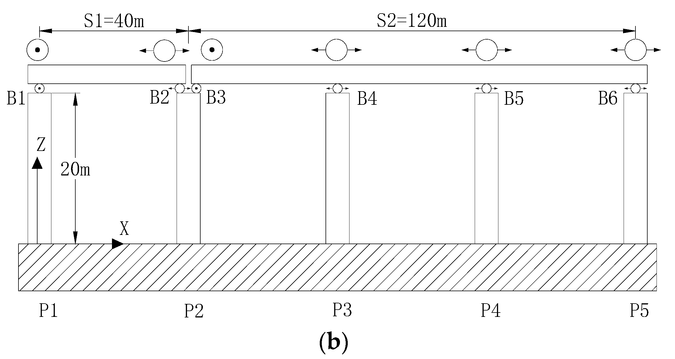
The pounding effects between superstructures on seismic performance of bridges have been studied by many researchers with software, such as ANSYS, ABAQUS, and MIDAS. The calculation efficiency is fast because the frequency of concentrated pounding is less. The commercial finite element software also cannot consider the energy loss in the pounding process. In this study, the pounding will occur at a spatial multipoint, and the pounding energy needs to be considered. Therefore, the software of FORTRAN is used to create a curved viaduct model and to simulate the pounding at a spatial multipoint in this analysis. A simply supported span (S1) and a continuous span (S2) form the curved viaduct, as shown in Figure 1. The total length of the viaduct is 160 m. The bridge alignment is horizontally curved in a circular arc with a radius of curvature of 200 m. In this figure, the X- and Y-axes lie in the horizontal plane, whilst the Z-axis is vertical.

2.1. Superstructures and Piers

The superstructure is composed of a concrete deck slab and three I-section steel girders (G1, G2, and G3). Full composite action between the slab and the girders is assumed for the linear elastic elements of the superstructure model, which is treated as a three-dimensional grillage beam system. The viaduct is designed according to the seismic design code of Japan [1]. The piers are steel piers with a hollow rectangular cross section and a height of 20 m. The cross-sectional properties of the superstructures and piers are summarised in Table 1. The steel and concrete densities are 7850 and 2500 kg/m3, respectively. Fibre element is used to simulate the pier. The constitutive model of the fibre regions is based on the uniaxial stress–strain relationship for each zone [22]. The interaction between the deck and pier motions is simulated by the transverse rigid bar [23].

2.2. Viscous Damper

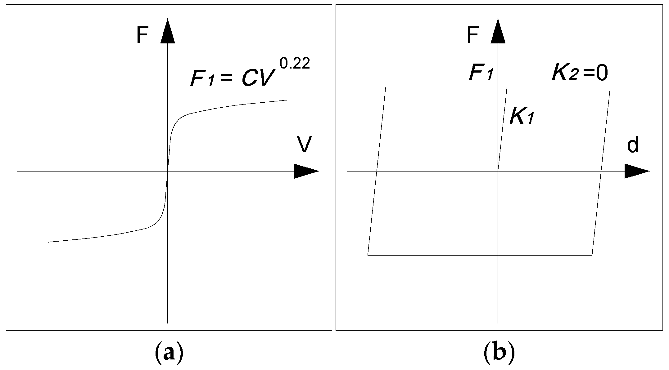
The schematic of a viscous damper is shown in Figure 2a. In this analysis, viscous dampers are anchored to the three girder ends connecting both adjacent superstructures across the expansion joint, as shown in Figure 2b. The relationship between resistance force and relative velocity is nonlinear, as shown in Figure 3. C is the attenuation coefficient, which is shown in Table 2. The viscous damper presents no resistance force under slow relative movements of segments due to thermal changes, creep, and shrinkage effects. It quickly begins to work only when an earthquake occurs. In other words, viscous dampers do not influence the normal service of the viaduct in a static state condition that is very well for a viaduct. Three stopper values (4, 6, and 8 cm) can be used in this analysis. Stopper values have an obvious effect on the relative velocity between adjacent superstructures. According to the calculation results, the maximum relative velocities between superstructures are 0.6, 0.7, and 0.8 m/s. The resistance forces of viscous dampers are derived from the maximum relative velocity, as shown in Table 2. Another relationship between force and displacement for a viscous damper is shown in Figure 3b. The force–displacement loop is nearly rectangular, and it presents relatively large energy dissipation capacity. The bridge seismic performance has been evaluated on five different kinds of viscous dampers (D0 indicating no viscous dampers). The structural properties of viscous dampers are shown in Table 2.

2.3. Bearing Supports and Stoppers

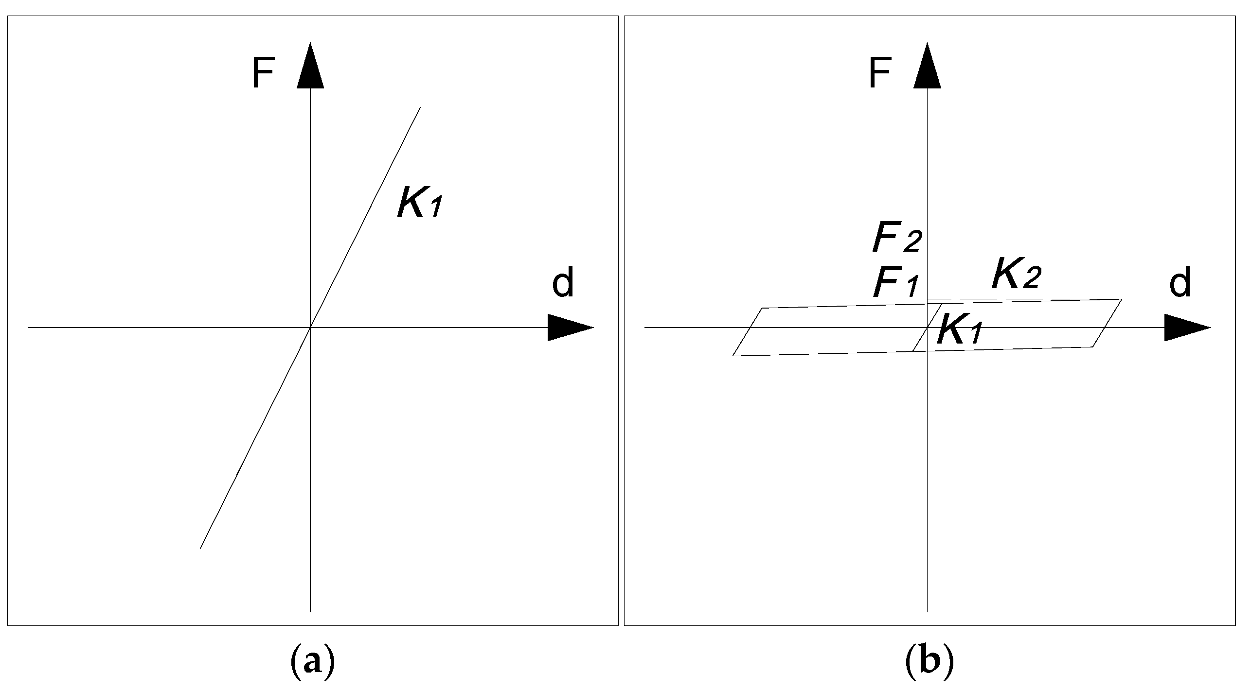
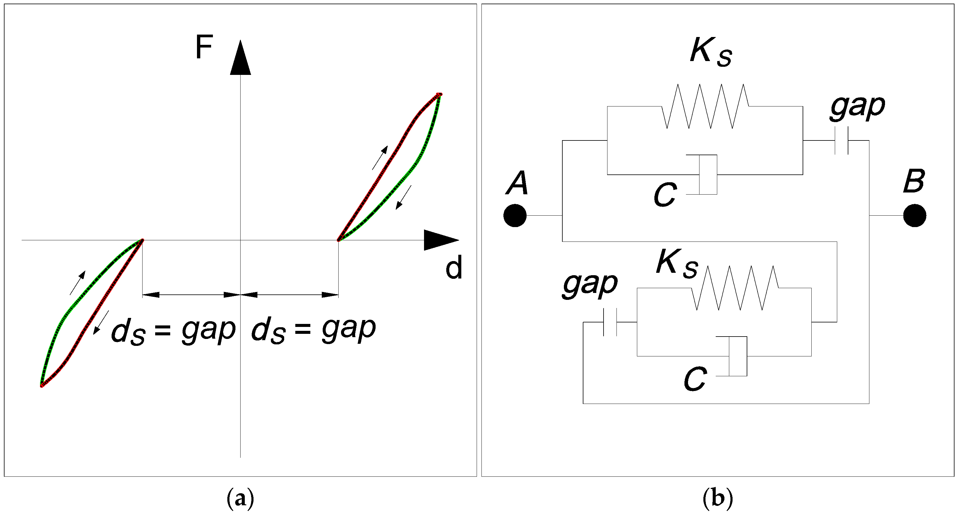
The bearing support layout including fixed and roller bearings is shown in Figure 4. The movements of the fixed bearing supports (F) are restrained in the longitudinal and transverse radial directions. Force–displacement relationship for fixed bearing supports is shown in Figure 5a. Roller bearing supports (R) can freely move in longitudinal direction, but they are restrained in transverse radial direction. Coulomb friction force is considered in numerical analysis for roller bearings, which are represented by using a trilinear element (Figure 5b). The structural properties of the steel bearing supports are shown in Table 3. The dispersed steel stoppers (D1–D4) are installed at a spatial multipoint near each roller bearing to limit excessive displacement of rollers. In this analysis, the pounding phenomenon at steel stopper is simulated by a modified Hertz-damp model, as shown in Figure 6a. The model can consider the energy dissipation in the pounding process, which can accurately simulate the pounding process. A nonlinear damper is activated during the approach period of the pounding to simulate the process of energy dissipation, which takes place mainly during that period in Figure 6b. During the restitution period, no energy dissipation occurs. The pounding force, F, for this type of pounding element is expressed as
F = { 0 for   δ < 0   ( no   contact ) , K s δ 3 / 2 + C δ for   δ 0 ,   δ > 0   ( contact - approach   period ) , K s δ 3 / 2 for   δ 0 ,   δ 0   ( contact - restitution   period ) , δ = x 1 x 2 d 0 C = 2 ξ ¯ K s δ m 1 m 2 m 1 + m 2 ,
where C is the pounding element’s damping, Ks is the pounding stiffness parameter, and the value is 780 MN/m; x1, x2 denote displacements of the structural members; d0 presents the initial distance between separation gap and the value is 4 cm, 6 cm, and 8 cm, respectively; m1 (1.86 × 10⁵ kg), m2 (7.38 × 10⁴ kg) are the mass of superstructure and pier, respectively; ξ ¯ is the damping ratio, and the value is 0.02.

3. Analysis Method

Elasto-plastic finite displacement dynamic response analysis is used as an analysis method in this study. The incremental equation of motion considers the effect of geometrical and material nonlinearities. The incremental finite element dynamic equilibrium equation at time t + ∆t over all the elements can be expressed in the following matrix form:
[ M ] { u ¨ } t + Δ t + [ C ] { u ˙ } t + Δ t + [ K ] t + Δ t { Δ u } t + Δ t = [ M ] { z ¨ } t + Δ t
Where [M], [C], and [K]t+∆t represent the mass, damping, and tangent stiffness matrices of the viaduct structure at time t + ∆t, respectively. In the meantime, u ¨ , u ˙ , Δ u and z ¨ denote the structural accelerations, velocities, incremental displacements, and earthquake accelerations at time t + ∆t, respectively.
A bilinear type is used to simulate the stress–strain relationship of beam–column element. The piers are made of steel. The elastic modulus is 200 GPa, and the yield stress is 235 MPa. The strain hardening coefficient is 0.01. Newmark’s step-by-step method of constant acceleration is adopted in this study to obtain the integration of the equations of motion. The Newton–Raphson iteration scheme is adopted to achieve the acceptable accuracy in the response calculations. The damping of the structure is also simulated by Rayleigh’s type. The damping coefficient of the structure is 2%. In this study, the program has been validated through a comparison with different commercial software, such as EDYNA, DYNA2E, and DYNAS [24].
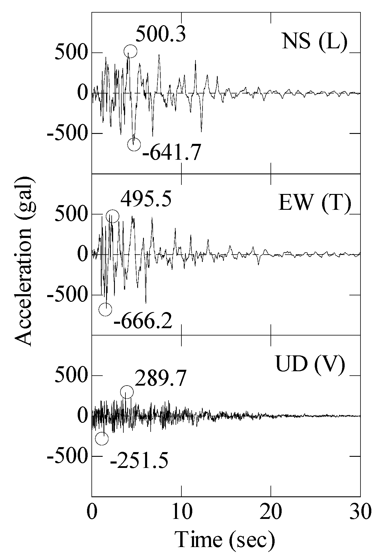
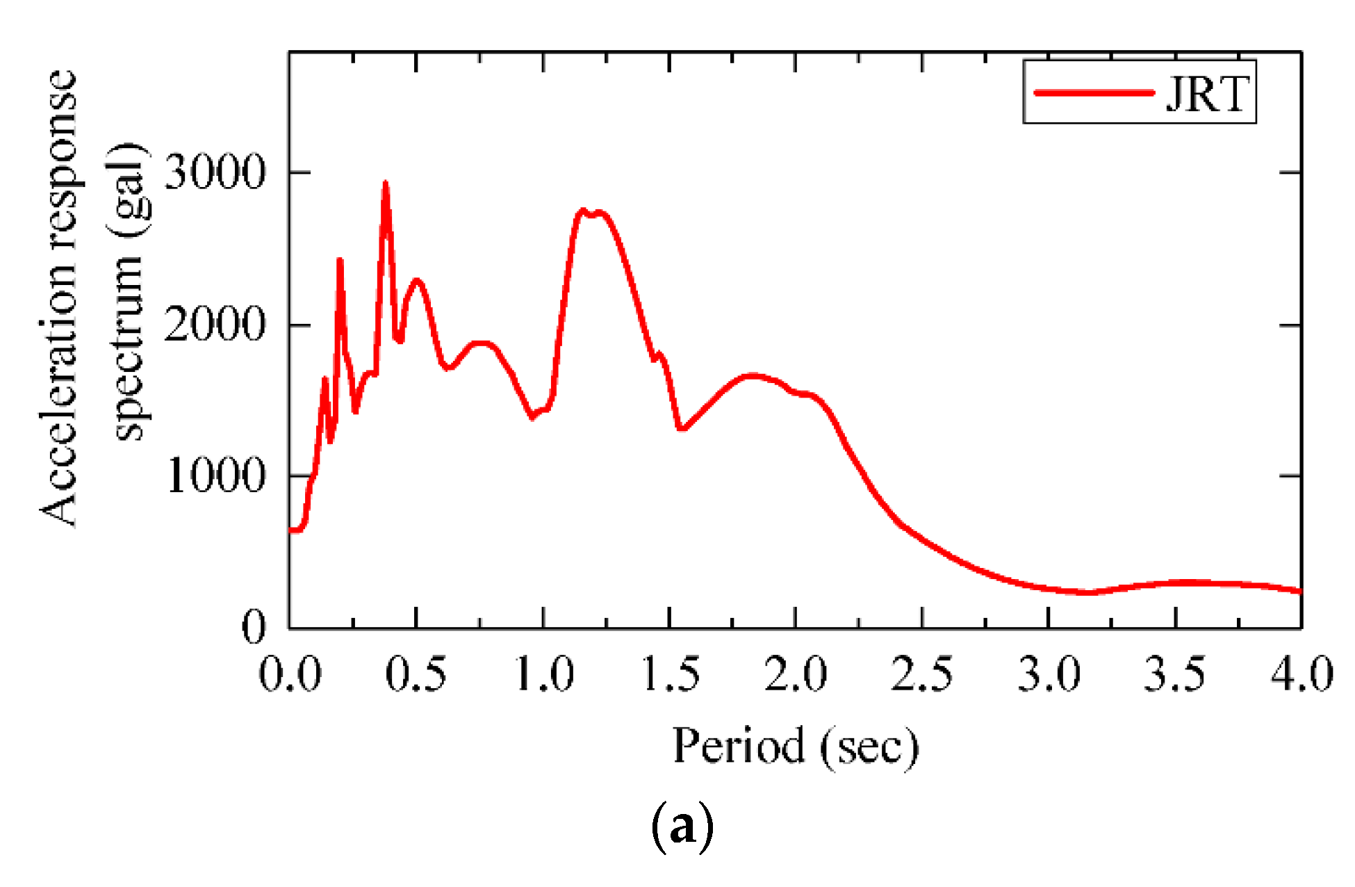
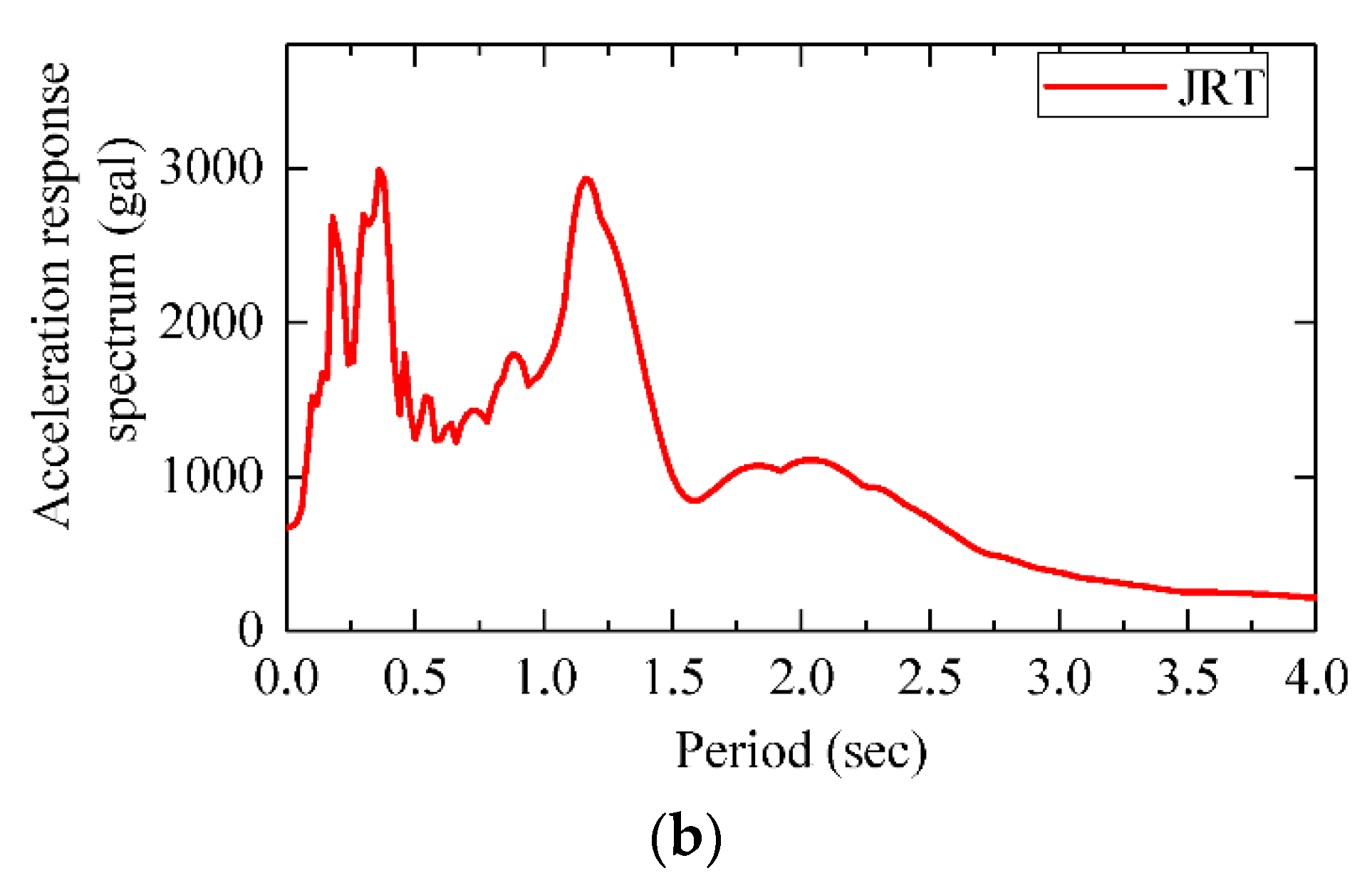
The input ground motion records are obtained from Takatori Stations (JRT) during the 1995 Kobe earthquake. Three direction earthquake records, namely, North–South (NS), East–West (EW), and Up–Down (UD), are shown in Figure 7. The NS component shakes the viaduct parallel to the X-axis in Figure 1, whilst the EW and UD components are acting in the Y- and Z-axes, respectively. The JRT record is characterised by high intensities of accelerations and velocities [25]. Thus, JRT is selected as input ground motion. The acceleration response spectrum for a damping ratio (ξ = 0.02) is shown in Figure 8. The fundamental natural periods for continuous span and simple supported span are 1.393 and 0.770 s, respectively.

4. Numerical Results

For an easy identification of the calculation cases, a specific nomenclature is adopted in this research. ‘D’ refers to viscous damper. Thus, ‘D100’ presents that the viscous damper type is D100. ‘D0’ indicates the viaduct without viscous dampers.

4.1. Deck Unseating Damage

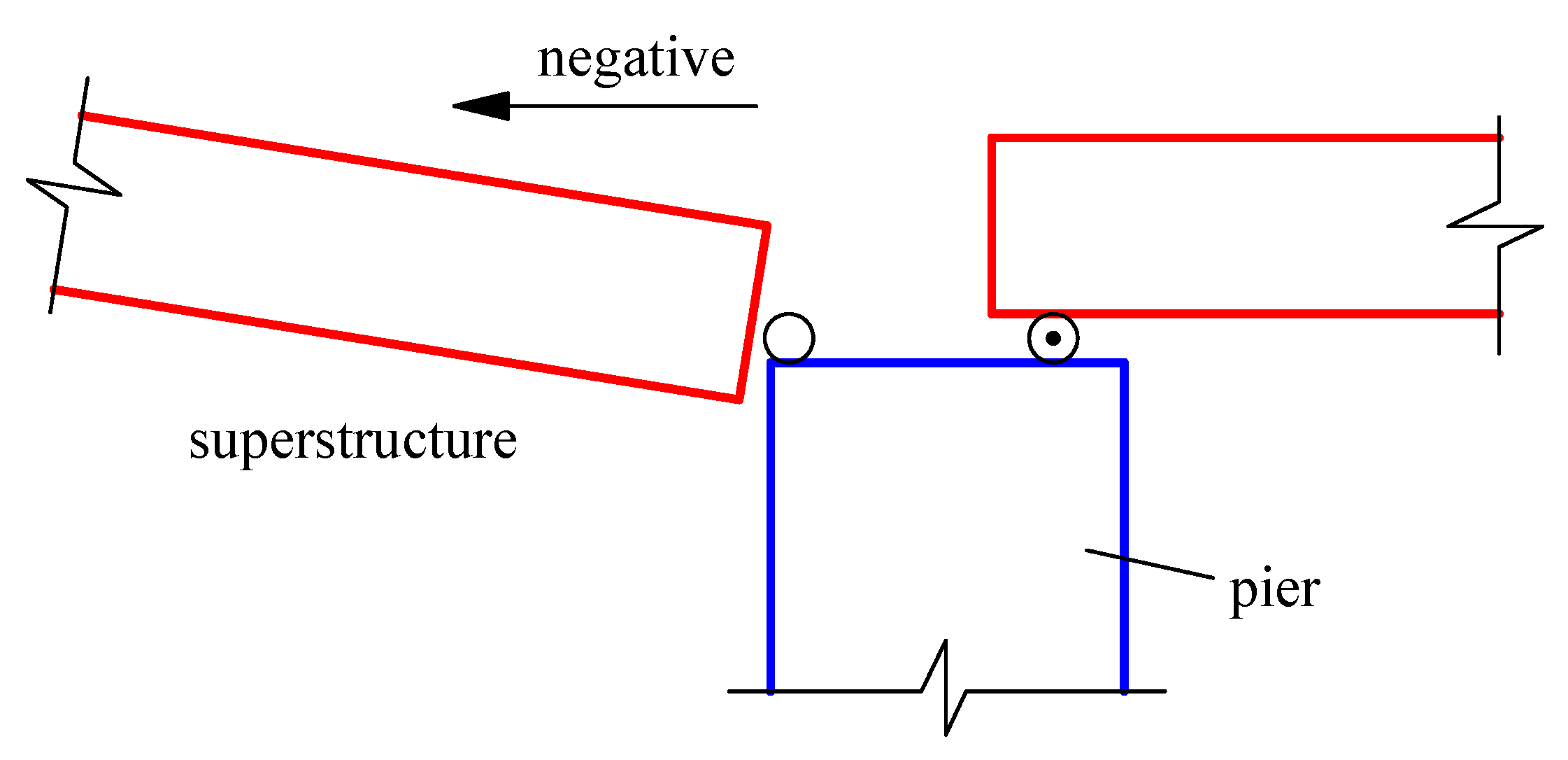
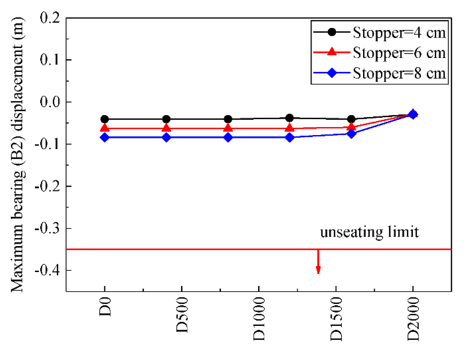
The maximum roller bearing (B2) displacement in negative tangential direction has been established as the damage index to evaluate the potential possibility of deck unseating, as shown in Figure 9. A limit of 0.35 m has been considered to indicate high unseating probability for the viaduct, with narrow steel pier caps that provide short seat widths.
Absolute values in all cases are less than the limit value, as shown in Figure 10. Maximum bearing (B2) displacement for negative direction presents nearly the same value with the stopper value, except the case of D2000. The stiffness and resistance force of viscous damper are insufficiently large to resist the structure movements. Thus, the stopper prevents the superstructure movements. As the stopper value increases, maximum bearing (B2) displacement for negative direction increases. Maximum bearing (B2) displacement in the case of D2000 also presents a least value. The resistance force and stiffness of D2000 are the largest amongst all the selected viscous dampers. Thus, the movement of roller bearing (B2) is relatively hard compared with other viscous dampers, which leads to the least displacement.

4.2. Relative Displacement between Superstructures

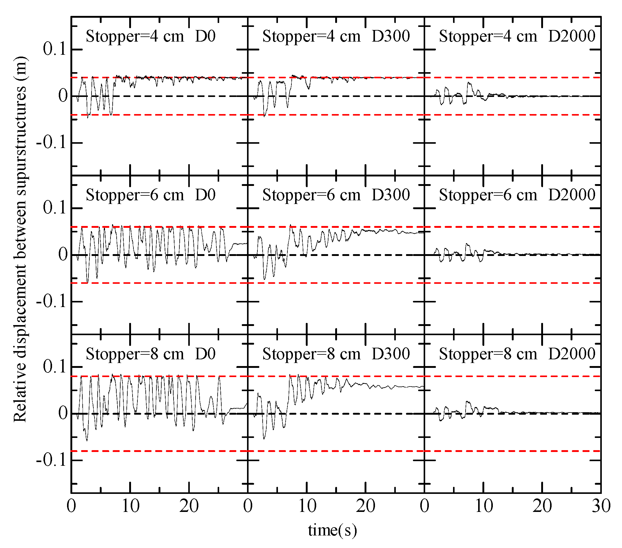
Relative displacement time history between superstructures, without viscous damper and with viscous damper, is presented in Figure 11. The results with viscous dampers (D300 and D2000) are only presented here because the results with other viscous dampers exhibit a similar response. The dashed red line presents the stopper value. A positive relative displacement of the expansion joint corresponds to opening of the joint gap, whilst a negative relative displacement corresponds to a closing. The viscous damper can greatly reduce the relative displacement between superstructures. Maximum relative displacement obviously decreases as the resistance force of viscous damper increases. However, maximum positive relative displacements present the same value with stopper value. Given that the positive relative displacement (outward) is larger than the stopper value, pounding between roller bearing (B2) and stopper occurs except the case of D2000. The stopper prevents the increase in maximum positive relative displacement. The resistance force of D2000 is the largest; thus, it could obviously reduce positive and negative relative displacements. Figure 12 shows the viscous damper force time history. D2000 presents the largest resistance force that can reduce relative displacement between superstructures. The case of D0 presents no viscous damper. Thus, the relative displacement between superstructures is the largest.

4.3. Bearing Forces and Pounding Forces

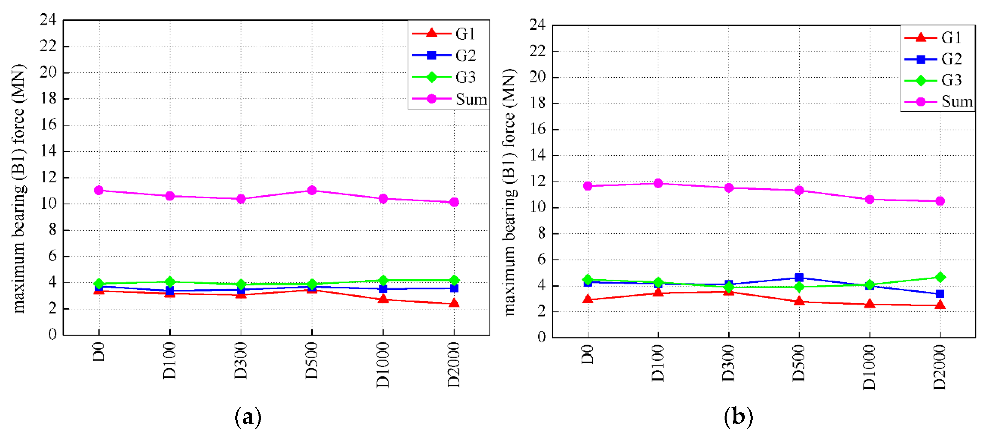
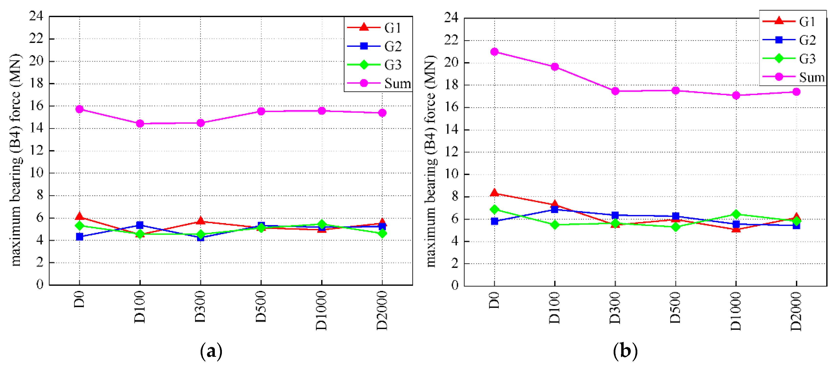
The maximum bearing (B1) forces and the maximum pounding forces (B4) are only presented here in Figure 13 and Figure 14, which represent the fixed bearing and the roller bearing forces, respectively, because the other bearing forces exhibit the similar change trend. The maximum fixed bearing (B1) forces and the maximum pounding forces (B4) increase with the rise in stopper value. The maximum pounding forces (B4) are much larger than the fixed bearing force.

4.4. Pier Damage

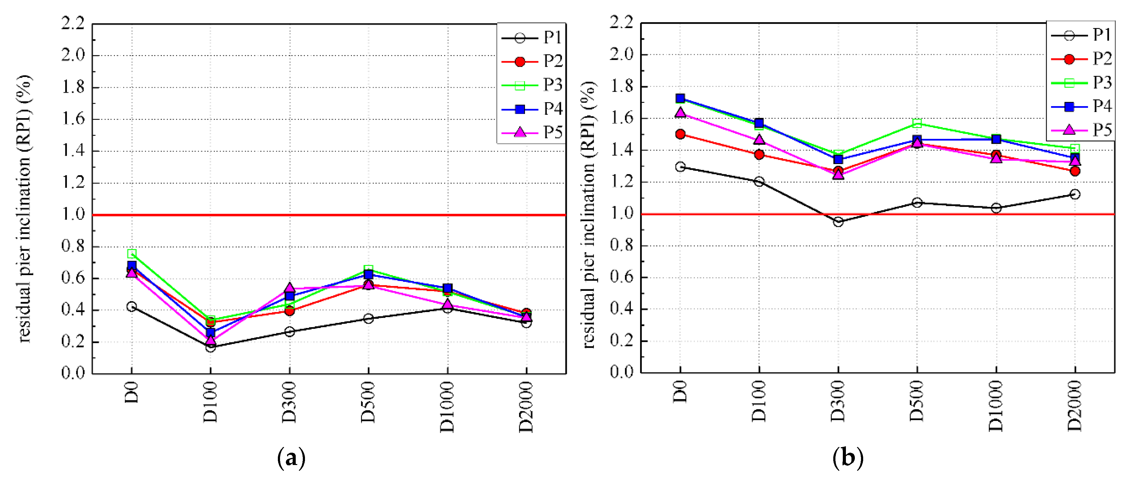
Superstructure supported on piers with large residual inclination may lose their serviceability and may even result in collapse. Residual pier inclination has been considered an important damage index in this analysis. The residual pier inclination of P1 exhibits the least residual pier inclination, as shown in Figure 15, compared with those of other piers. The fixed bearing is placed on the top of P1, and the roller bearings equipped with steel stoppers are placed on other tops of piers. Pounding force between roller bearing and stopper is much larger than fixed bearing force in Figure 13 and Figure 14, which lead to less residual pier inclination of P1. Given that a large stopper value leads to large pounding forces, residual pier inclination in case of a stopper value of 8 cm is larger than that in the case of a stopper value of 4 cm. Residual pier inclination and residual curvature present nearly the same change trend, as shown in Figure 15 and Figure 16. The local buckling of the pier base is the reason for the residual pier inclination of the pier. Residual pier inclination does not present an obvious difference value when different viscous dampers are provided in Figure 15. The resistance force and the stiffness of viscous damper do not obviously influence the residual pier inclination. However, residual pier inclination without viscous dampers presents larger value than those with viscous dampers in the case of the same stopper value. The reason is that viscous dampers could dissipate some energy to a certain degree.

4.5. Relationship of Bending Moment and Curvature

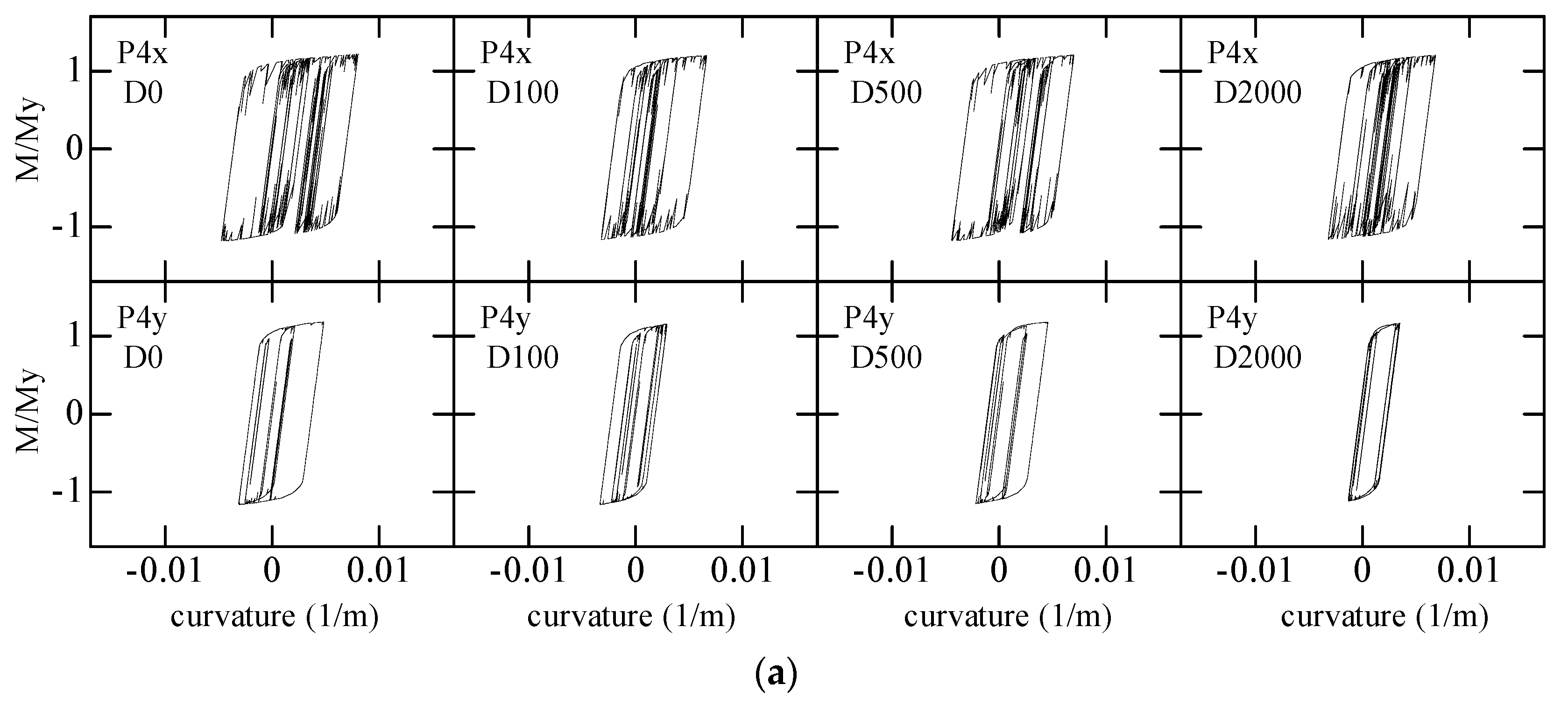
In this analysis, central pier (P4) of continuous span, which supports more weight and shall afford more inertial force during earthquakes, is likely subjected to large pounding forces between roller bearing and stopper during earthquakes. Therefore, the hysteretic curve of bending moment to curvature at pier bases for P4 in X and Y direction in cases of D0, D100, D500, and D2000 are shown Figure 17. M and My represent bending moment and yield bending moment, respectively. The hysteretic curve of bending moment to curvature at other pier bases present similar results. Figure 17 shows that the absolute value of M/My overpasses 1 in X and Y directions, which indicates plastic deformation at pier base in the two directions. Maximum bending moment and maximum curvature in X direction are larger than those in Y direction. All the bearings are restrained in Y direction, which leads to relatively less bearing forces. Thus, maximum bending moment and maximum curvature at pier bases in X direction play a more important effect on the damage of pier bases. As stopper value increases, maximum bending moment and maximum curvature at pier bases in X direction obviously increase. However, maximum bending moment and maximum curvature at pier bases do not exhibit a significant difference in case of different viscous dampers applied on the viaduct. In other words, the type of viscous dampers does not affect the maximum bending moment and maximum curvature at pier bases. Viaduct equipped with a viscous damper also presents less maximum bending moment and less maximum curvature at pier bases than those without viscous dampers. In conclusion, stopper value plays a more important role in maximum bending moment and maximum curvature at pier bases than viscous dampers.

5. Conclusions

The overall performance of viaducts with different kinds of viscous dampers and different stopper values is evaluated during serious earthquakes in this study. Application of viscous dampers and stoppers to reduce some kinds of viaduct damage is also proven. Stopper value plays a more important role in pier damage than viscous damper. The analysis results provide sufficient evidence for the following conclusions:
(1) Calculated results demonstrate that a stopper could effectively reduce the possibility of deck unseating. However, the possibility of deck unseating could also be significantly reduced in the case of D2000 because of its large resistance force and stiffness;
(2) Maximum closing relative displacement could be greatly reduced in the case of viscous dampers. Maximum closing relative displacement also obviously decreases as the resistance force and stiffness of damper increase. However, a stopper could greatly reduce maximum opening relative displacement;
(3) Viaducts with less stopper value present less residual pier inclination. As stopper value increases, residual pier inclination rises. Pounding force between roller bearing and stopper is much larger than fixed bearing force. Thus, P1 with fixed bearings on top of it exhibits the least residual pier inclination compared with other piers. Viaducts with viscous dampers present less residual pier inclination than those without viscous dampers. However, the resistance force and stiffness of a damper do not obviously affect the residual pier inclination. Residual pier inclination and residual curvature at pier bases present similar trend for all cases;
(4) Plastic deformations at pier bases appear in X and Y directions during earthquakes. Maximum bending moment and maximum curvature at pier bases in X direction are larger than those in Y direction. Thus, maximum bending moment and maximum curvature at pier bases in X direction play a more important role in the damages of pier bases. In the case of same viscous damper, maximum bending moment and maximum curvature at pier bases obviously increase with the rise in stopper value. A viaduct equipped with a viscous damper presents less maximum bending moment and less maximum curvature at pier bases than those without viscous dampers. However, the type of viscous dampers does not affect the maximum bending moment and maximum curvature at pier bases. Stopper value plays a more important role in maximum bending moment and maximum curvature than viscous dampers.

Author Contributions

Conceptualization, Q.T.; methodology, C.K. and Q.T.; software, C.K. and Q.T.; validation, L.Z.; formal analysis, Q.T.; resources, Q.T.; data curation, C.K. and Q.T.; writing—original draft preparation, C.K., Q.T. and L.Z.; writing—review and editing, C.K.; project administration, Q.T.; funding acquisition, Q.T. All authors have read and agreed to the published version of the manuscript.

Funding

This research was funded by the Natural Science Foundation of China, grant number 52168023; the National Science Foundation for Young Scientists of Jiang Xi, grant number 20161BAB216113; the Natural Science Foundation of Jiang Xi, grant number 20171BAB206050; and the China Postdoctoral Science Foundation, grant number 2017M611993.

Conflicts of Interest

The authors declare no conflict of interest.

References

  1. Japan Road Association. Specifications for Highway Bridges—Part V Seismic Design; Japan Road Association: Tokyo, Japan, 2012. (In Japanese) [Google Scholar]
  2. Itani, A.M.; Bruneau, M.; Carden, L.; Buckle, I.G. Seismic behavior of steel girder bridge superstructures. J. Bridge Eng. 2004, 9, 243–249. [Google Scholar] [CrossRef]
  3. Taflanidis, A.A. Optimal probabilistic design of seismic dampers for the protection of isolated bridges against near-fault seismic excitations. Eng. Struct. 2011, 33, 3496–3508. [Google Scholar] [CrossRef]
  4. Li, B.; Bi, K.M.; Chouw, N.; Butterworth, J.W.; Hao, H. Experimental investigation of spatially varying effect of ground motions on bridge pounding. Earthq. Eng. Struct. Dyn. 2012, 41, 1959–1976. [Google Scholar] [CrossRef]
  5. Hao, H.; Bi, K.M.; Chouw, N.; Ren, W.X. State-of-the-art review on seismic induced pounding response of bridge structures. J. Earthq. Tsunami 2013, 7, 1350019. [Google Scholar] [CrossRef]
  6. Zanardo, G.; Hao, H.; Modena, C. Seismic response of multi-span simply supported bridges to a spatially varying earthquake ground motion. Earthq. Eng. Struct. D 2002, 31, 1325–1345. [Google Scholar] [CrossRef]
  7. Mendez Galindo, C.; Gil Belda, J.; Hayashikawa, T. Non-linear seismic dynamic response of curved steel bridges equipped with LRB supports. Steel Constr. 2010, 3, 34–41. [Google Scholar] [CrossRef]
  8. Tian, Q.; Hayashikawa, T.; Song, G.Q.; Zhang, C. Study on the effect of cable restrainers stiffness on the seismic performance of curved viaducts combined use of steel stoppers. J. Earthq. Tsunami 2019, 13, 1950006. [Google Scholar] [CrossRef]
  9. Tian, Q.; Hayashikawa, T.; Ren, W.X. Effectiveness of shock absorber device for damage mitigation of curved viaduct with steel bearing supports. Eng. Struct. 2016, 109, 61–74. [Google Scholar] [CrossRef]
  10. Tian, Q.; Hayashikawa, T.; Xiong, J.G.; Lei, B. Seismic performance of curved viaducts with shock absorber devices of different stiffness in great earthquakes. J. Earthq. Tsunami 2018, 12, 1850013. [Google Scholar] [CrossRef]
  11. Maghsoudi-Barmi, A.; Khansefid, A.; Khaloo, A.; Moeini, M.E. Probabilistic seismic performance assessment of optimally designed highway bridge isolated by ordinary unbonded elastomeric bearings. Eng. Struct. 2021, 247, 113058. [Google Scholar] [CrossRef]
  12. Maghsoudi-Barmi, A.; Khansefid, A.; Khaloo, A.; Ehteshami Moeini, M. Seismic risk assessment of optimally designed highway bridge isolated by ordinary unbounded elastomeric bearings. Numer. Methods Civ. Eng. 2021, 6, 10–21. [Google Scholar] [CrossRef]
  13. Khaloo, A.; Maghsoudi-Barmi, A.; Moeini, M.E. August. Numerical parametric investigation of hysteretic behavior of steel-reinforced elastomeric bearings under large shear deformation. Structures 2020, 26, 456–470. [Google Scholar] [CrossRef]
  14. Kawashima, K.; Unjoh, S. Seismic response control of bridges by variable dampers. J. Struct. Eng. ASCE 1994, 120, 2583–2601. [Google Scholar] [CrossRef]
  15. Wu, Y.X.; Huang, J.; Lin, S.Z.; Qi, A. Design and application status of seismic isolation constitution of building. China Civ. Eng. J. 2018, 51, 62–73, 94. [Google Scholar]
  16. Khedmatgozar Dolati, S.S.; Mehrabi, A.; Khedmatgozar Dolati, S.S. Application of viscous damper and laminated rubber bearing pads for bridges in seismic regions. Metals 2021, 11, 1666. [Google Scholar] [CrossRef]
  17. Ruangrassamee, A.; Kawashima, K. Control of nonlinear bridge response with pounding effect by variable dampers. Eng. Struct. 2003, 25, 593–606. [Google Scholar] [CrossRef]
  18. Hwang, J.-S.; Tseng, Y.-S. Design formulations for supplemental viscous dampers to highway bridges. Earthq. Eng. Struct. D 2005, 34, 1627–1642. [Google Scholar] [CrossRef]
  19. Domaneschi, M. Feasible control solutions of the ASCE benchmark cable-stayed bridge. Struct. Control. Health Monit. 2010, 17, 675–693. [Google Scholar] [CrossRef]
  20. Talyan, N.; Elias, S.; Matsagar, V. Earthquake response control of isolated bridges using supplementary passive dampers. Pract. Period. Struct. 2021, 26, 04021002. [Google Scholar] [CrossRef]
  21. Chen, X.; Xiong, J. Seismic resilient design with base isolation device using friction pendulum bearing and viscous damper. Soil Dyn. Earthq. Eng. 2022, 153, 107073. [Google Scholar] [CrossRef]
  22. Mendez Galindo, C.; Ruiz Julian, F.D.; Hayashikawa, T. Seismic performance of isolated curved steel viaducts under level II earthquakes. J. Struct. Eng. 2009, 55, 699–708. [Google Scholar]
  23. Maleki, S. Effect of deck and support stiffness on seismic response of slab-girder bridges. Eng. Struct. 2002, 24, 219–226. [Google Scholar] [CrossRef]
  24. Abdel Raheem, S.E. Pounding mitigation and unseating prevention at expansion joints of isolated multi-span bridges. Eng. Struct. 2009, 31, 2345–2356. [Google Scholar] [CrossRef]
  25. Somerville, P.G. Magnitude scaling of the near fault rupture directivity pulse. Phys. Earth Planet. Inter. 2003, 137, 201–212. [Google Scholar] [CrossRef]
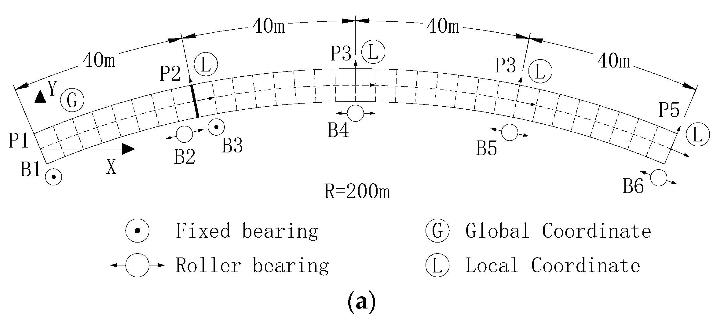
Figure 1. Analytical model of the viaduct. (a) Plan view of the curved highway viaduct model. (b) Elevation view of the curved highway viaduct model.
Applsci 12 08207 g001aApplsci 12 08207 g001b
Figure 2. Analytical model of expansion joint. (a) Analytical model of expansion joint. (b) Finite element model of expansion joint.
Applsci 12 08207 g002
Figure 3. Analytical model of viscous damper. (a) Force–velocity. (b) Force–displacement.
Applsci 12 08207 g003
Figure 4. Elevation view of finite element model of curved viaduct.
Applsci 12 08207 g004
Figure 5. Force–displacement relationships for steel bearing supports. (a) Fixed bearing. (b) Roller bearing.
Applsci 12 08207 g005
Figure 6. Force–displacement relationships for steel stoppers. (a) Modified Hertz-damp model. (b) Pounding element model.
Applsci 12 08207 g006
Figure 7. Recording of 1995 Kobe earthquake by Japan Railway Takatori Station of (JRT).
Applsci 12 08207 g007
Figure 8. Acceleration response spectra (ξ = 0.02). (a) Longitudinal direction. (b) Transverse direction.
Applsci 12 08207 g008aApplsci 12 08207 g008b
Figure 9. Schematic of deck unseating.
Applsci 12 08207 g009
Figure 10. Possibility of deck unseating damage.
Applsci 12 08207 g010
Figure 11. Relative displacement between superstructures.
Applsci 12 08207 g011
Figure 12. Viscous damper force time history.
Applsci 12 08207 g012
Figure 13. Maximum bearing (B1) forces in tangential direction. (a) Stopper = 4 cm. (b) Stopper = 8 cm.
Applsci 12 08207 g013
Figure 14. Maximum pounding forces between roller bearing (B4) and stopper in tangential direction. (a) Stopper = 4 cm. (b) Stopper = 8 cm.
Applsci 12 08207 g014
Figure 15. Residual pier inclination. (a) Stopper = 4 cm. (b) Stopper = 8 cm.
Applsci 12 08207 g015
Figure 16. Ratio of residual curvature to yield curvature. (a) Stopper = 4 cm. (b) Stopper = 8 cm.
Applsci 12 08207 g016
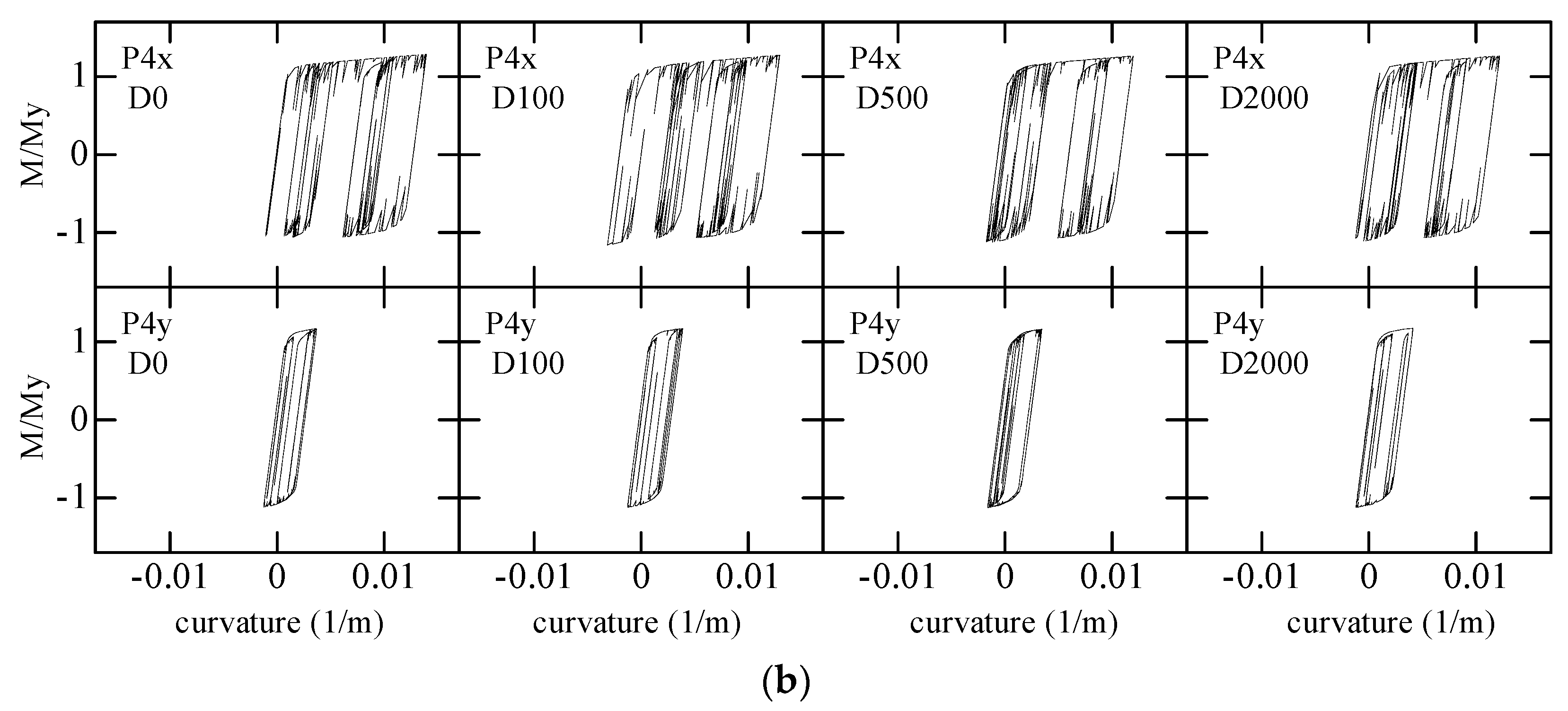
Figure 17. Hysteretic curve of bending moment to curvature at pier bases (P4). (a) Stopper = 4 cm. (b) Stopper = 8 cm.
Applsci 12 08207 g017aApplsci 12 08207 g017b
Table 1. Cross-sectional properties of girders and piers.
Pier or GirderA (m2)Ix (m4)a Iy (m4)
P10.45000.37980.3798
P20.47000.43290.4329
P30.47000.43290.4329
P40.47000.43290.4329
P50.45000.37980.3798
G10.21000.10050.0994
G20.42000.16090.2182
G30.21000.10050.0994
a Iz in the cases of G1, G2, and G3.
Table 2. Structural properties of viscous dampers.
Type of DamperAttenuation Coefficient
C
Power Exponent
α
Stiffness
K1 (MN/m)
Stopper = 4 cmStopper = 6 cmStopper = 8 cm
Resistance Force F1 (MN)Resistance Force F1 (MN)Resistance Force F1 (MN)
D0
D1001170.22900.1050.1080.111
D3003500.221300.3130.3240.333
D5005830.222000.5210.5390.555
D100011650.224001.0411.0771.109
D200023300.228002.0822.1542.218
Table 3. Structural properties of steel bearing supports.
Bearing TypeK1
(MN/m)
K2
(MN/m)
F1
(MN)
F2
(MN)
Fixed980---
Roller49.00.00980.07350.0754
Publisher’s Note: MDPI stays neutral with regard to jurisdictional claims in published maps and institutional affiliations.