Article

Shear-Bond Behaviour of Profiled Composite Slab Incorporated with Self-Compacted Geopolymer Concrete

School of Engineering, Deakin University, Geelong, VIC 3217, Australia
*
Author to whom correspondence should be addressed.
Appl. Sci. 2022, 12(17), 8512; https://doi.org/10.3390/app12178512
Submission received: 23 March 2022 / Revised: 22 August 2022 / Accepted: 23 August 2022 / Published: 25 August 2022
(This article belongs to the Section Civil Engineering)

Abstract

:
Composite slab systems have become increasingly popular over the last few decades because of the advantages of merging the two building materials, profiled steel sheets and concrete. The profiled composite slab’s performance depends on the composite interaction at the longitudinal direction of the concrete–steel interface. Geopolymer concrete has emerged over the last few years as a potential sustainable construction material, with 80% less carbon dioxide emissions than cementitious concrete. Recently, self-compacted geopolymer concrete (SCGC) has been developed, synthesised from a fly ash/slag ratio equal to 60/40, micro fly ash (5%), anhydrous sodium metasilicate solid powder as the alkali-activator and a water/solid content ratio equal to 0.45. The production of SCGC eliminates the need for an elevated temperature during curing and high corrosive alkali-activator solutions, as in traditional geopolymer concrete. The bond characteristics of the profiled composite slab system incorporated with the SCGC mix have not yet been thoroughly investigated. The cost-effectiveness of small-scale tests has popularised its usage by many researchers as an alternative technique to large-scale testing for assessing composite slab load shear capacity. In this paper, small-scale push tests were conducted to investigate the load slip behaviour of the SCGC composite slab compared to the normal concrete (NC) composite slab, with targeted compressive strengths of 40 and 60 MPa. The results indicate that SCGC has better chemical adhesion with profiled steel sheets than NC. Additionally, the profiled composite slab incorporated with SCGC possesses higher ultimate strength and toughness than the normal concrete composite slab.

1. Introduction

The built environment is responsible for about 39% of global carbon dioxide emissions [1,2]. According to the worldwide status report in 2017, published by the UN Environment and the International Energy Agency, 28% of carbon dioxide emissions are caused by the energy required for cooling, heating and lighting buildings. In contrast, 11% of the remaining carbon dioxide emissions are linked to the operation of construction material production. Concrete is one of the most commonly used construction materials, with an estimated annual use rate of 1.4 m3 per person [3]. Cement material production only is responsible for around 7% of worldwide carbon dioxide emissions [3,4,5,6,7]. In Australia, concrete accounts for more than half of construction material. Approximately 30 million tonnes of building materials are produced yearly to meet the demands of population growth and economic progress. Due to the ozone depletion and global warming challenge, the building industry has recently become more conscious of the importance of using environmentally sustainable construction materials. Immense interest in sustainable construction materials has recently arisen. It aligns with the pioneering vision of the World Green Building Council’s (WorldGBC) approach to net-zero carbon emissions by 2050.
Geopolymer concrete is synthesised by the chemical reaction of by-product compounds, including fly ash, slag, metakaolin, high calcium wood ash and rice husk ash, with an alkaline solution, such as sodium hydroxide (NaOH) and sodium silicate (Na2SiO3) [8]. Geopolymer concrete as a replacement for cementitious concrete has been the focus of many researchers in the last few decades. It mainly returns to the low negative environmental impact, as carbon dioxide emissions are 80% less than normal concrete [9,10,11], along with recycling by-products waste materials, such as fly ash and slag, which cause serious harm to the environment if not stored properly. For example, 12 million tons of fly ash are produced yearly in Australia by coal-fired power plants, which constitute 18% of the total waste stream in Australia. Several studies concluded that geopolymer concrete has excellent mechanical properties, including high compressive strength and adequate flexural strength [12,13], high chemical resistance [14,15], and excellent bond strength with steel reinforcement [16,17]. Moreover, fly ash/slag-based geopolymer concrete (FSGC) has excellent resistance to the freeze–thaw cycle, comparable to normal concrete [18]. In addition, geopolymer concrete has better chemical stability, which culminates in its performance with better mechanical characteristics and durability during intense heat than its counterparts [19].
Despite many advantages of geopolymer concrete, its utilisation in the construction industry is minimal, mainly because of two obstacles that hinder its usage beyond the structural precast elements. Geopolymer concrete must be cured at a temperature range of 60–85 °C for 24 h to achieve a comparable compressive strength to conventional concrete [20,21,22]. In addition, alkali-activator solutions must be prepared before the day of casting, and they have a high corrosive property that necessitates special handling and storage techniques [23,24,25,26]. Recently, Rahman and Al-Ameri (2021) [13] developed a self-compacted geopolymer concrete (SCGC) cured at ambient temperature with compressive strength of 40 MPa and tensile strength of 3 MPa. The binders used to synthesise the geopolymer concrete were a fly ash/slag ratio equal to 60/40, micro fly ash (5%), anhydrous sodium metasilicate solid powder as the alkali-activator and water/solid content ratio equal to 0.45. This newly developed SCGC eliminates the need for high corrosive alkali activator solutions for production and elevated temperatures for curing.
Composite slab systems have become increasingly popular over the last few decades because of the advantages of merging the two building materials, profiled steel sheets and concrete. The profiled steel sheet is integral in reinforcing the concrete and serves as a secure scaffolding platform for construction workers during the construction stage, thus saving time and cost [27,28]. Compared to other alternative construction techniques, composite steel-concrete structures are more cost-effective, as they require less construction time and reduced cross-sectional areas [29]. Three main failure modes (flexural failure, vertical shear failure and longitudinal shear failure) have been identified in composite slab systems under the bending moment load [30]. Out of three dominant failure modes, the composite profiled slab system is more prone to longitudinal shear failure than the other two failure modes [31].
The bond strength of a composite slab depends on the efficiency of chemical adhesion, mechanical interlocks, and frictional resistance [27,28,32,33,34,35,36]. The chemical adhesion bond between concrete and the profiled deck is initially responsible for transferring the longitudinal shear forces and inducing a resistance that prevents the occurrence of longitudinal slip [37,38]. The high shear forces lead to bond strength degradation, and consequently, the significance of the interface embossments at profiled steel sheets emerges by hindering the rapid interface slippage [39,40]. The frictional bond at the concrete-profiled steel sheet interface is induced during the slippage process, due to the applied pressure by the weight of the hardened concrete slab. The variance in properties between concrete (brittle material) and profiled steel sheet (ductile material), in terms of plastic deformation, results in an inefficient steel-concrete shear bond that leads to brittle failure and low durability of the composite structure [28]. Therefore, a more ductile property of hardened concrete results in a better bond performance of the profiled composite slab system.
The transfer of longitudinal shear forces at the concrete-profiled steel sheet interface has been identified as complex to be mathematically modelled. Small-scale tests [30,39,40,41,42,43,44,45,46,47,48,49,50] have been used as an alternative to full-scale bending tests, due to their simplicity and lower construction cost. In the last few decades, different small-scale push test set-ups have been designed to measure and understand the composite interaction behaviour of composite slabs. Some researchers favoured the vertically loaded set-up [38,42,44,48], where profiled steel sheets sandwiched normal concrete, as shown in Figure 1a–c or encased the profiled steel sheets symmetrically, as shown in Figure 1d. However, concrete delamination, handling issues and local buckling were experienced in vertical specimens with lengths over 1 m [38].
Other studies adopted horizontal-loaded test setups [45,51]. Concrete is cast on the profiled steel sheet, so the concrete self-weight reflects the composite interaction at the concrete–steel interface. Constant and variant clamping forces were applied vertically on the hardened concrete to measure its effect on the frictional resistance. However, a few factors were not adequately simulated in the push tests, including the influence of slab slenderness, frictional resistance provided due to end supports, bending curvature and tensile straining in profiled sheets [50]. As a result, a small-scale block bending test, as shown in Figure 1e, was developed by An (1993) [52] to overcome the observed drawbacks. Nevertheless, the bending effect was not adequately performed, due to the specimen’s small length and the test equipment’s nature. Moreover, specimen handling and storage issues were challenging [53].
Recently, two horizontal small-scale test set-ups were suggested by Yi et al. (2021) [40], namely push-off and pull-out tests, as shown in Figure 1f,g, respectively. The aim was to investigate the bond stress-slip behaviour of crumbed rubber concrete composite slabs, compared to normal concrete composite slabs. The obtained results from the two different test set-ups were validated numerically using ABAQUS software to advise which small-scale test setup could be used for further investigation in future studies. The bond strength results obtained from the pull-out numerical analysis showed an overestimation of the bond stress. Roughly 100 times deformation was observed in the profiled steel sheet compared to the results from the push-off numerical analysis. As a result, the pull-out test set-up is not advised as an experimental method for assessing the bond characteristics of a composite slab. In this sense, a test set-up is developed, similar to the push-off test set-up adopted in Yi et al.’s (2021) [40] study, to evaluate the bond characteristics of the SCGC composite slab.

Research Significance

Due to their advantages in the past few years, there has been increasing research into geopolymer concrete composites and their application in various structural composites, including beams [54,55,56,57,58] and columns [59,60,61]. However, to the best of the author’s knowledge, the uniqueness of this study is that no previous investigation has been conducted to investigate the bond characteristics of profiled composite slabs incorporated with self-compacted geopolymer concrete. Previous small-scale studies investigated the bond stress-slip behaviour of normal concrete composite slabs with trapezoidal profiled steel sheets [31,41,42,43,45,46,53,62,63,64,65,66], with limited studies investigating the bond characteristics of dovetailed profiled sheets with normal concrete [39,40]. This study will help us to understand the bond characteristics between the dovetailed profiled steel sheet and SCGC. Moreover, the bond behaviour results will be compared to the results from the cementitious profiled composite slab to investigate the difference between both behaviours. The push test was conducted on six specimens, comprising two SCGC composite slabs and four NC composite slabs. The interface bond characteristics of the SCGC composite slab with design compressive strength of 40 MPa are compared to the NC composite slab with design compressive strength of 40 and 60 MPa.

2. Material and Methodology

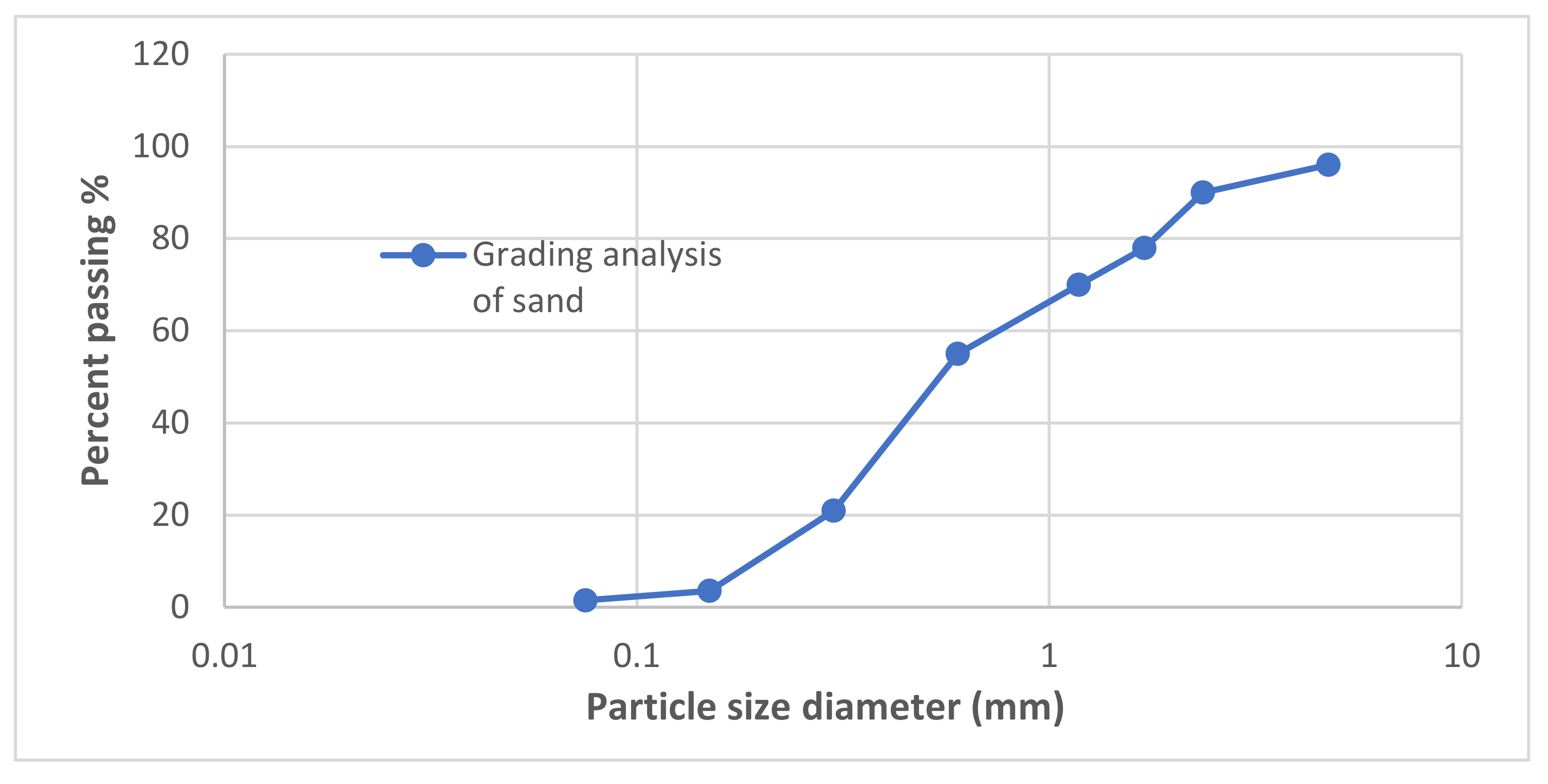
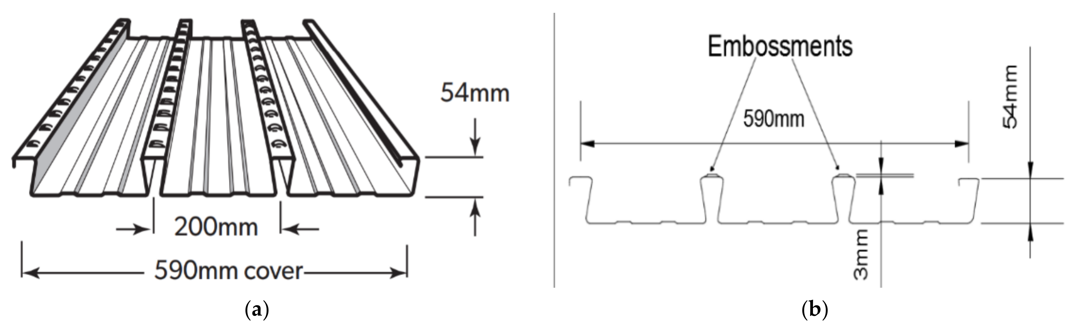
2.1. Material Properties

This study used the new SCGC mix design, developed recently at Deakin University by Rahman and Al-Ameri in 2021 [13]. The mix comprises a fly ash/slag ratio equal to 60/40, micro fly ash equal to 5%, water/solid content equal to 0.45, and solid anhydrous sodium metasilicate as an alkali activator. Fly ash grade 1 complies with the Australian Standards AS/NZS 3582.1:2016 [67] and was sourced from Cement Australia. Ground slag was produced by Independent Cements. Solid sodium metasilicate anhydrous beaded was sourced from Chemist supply. A 5% micro fly ash was sourced from Fly Ash Australia Pty. Ltd. The material properties and chemical composition of the SCGC binder constituents are presented in Table 1 and Table 2. The coarse aggregate to the fine aggregate ratio used in this study was 0.53:0.47. The fine aggregate grading analysis used in the study complies with the Australian Standards AS 1141.3.1:2021 [68], as presented in Figure 2. Boral Construction supplied the aggregate for this test program. General purpose cement procured from Cement Australia was used to produce the normal concrete. The mix designs of the self-compacted geopolymer concrete (SCGC), normal concrete with a compressive design strength of 40 MPa (NC40) and normal concrete with a compressive design strength of 60 MPa (NC60) are presented in Table 3. The Bondek® profiled steel sheet, as shown in Figure 3a,b, was procured from Lysaght and used in this study. Table 4 presents the material specification of a 1 mm thickness profiled steel sheet.

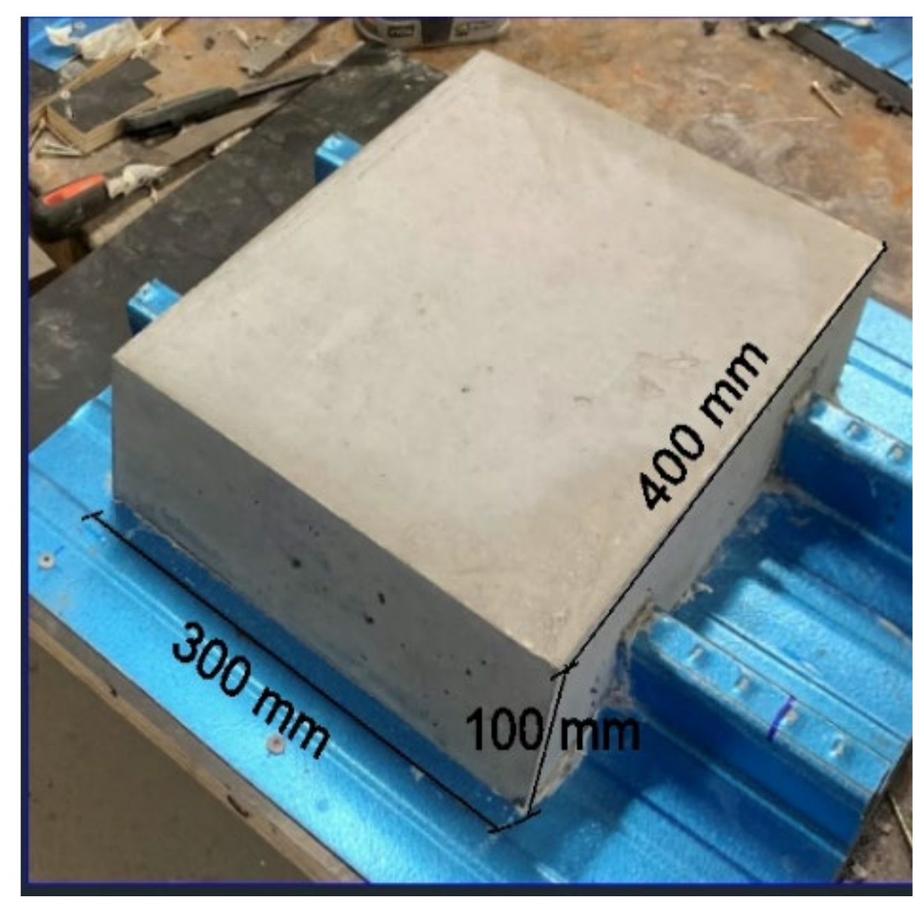
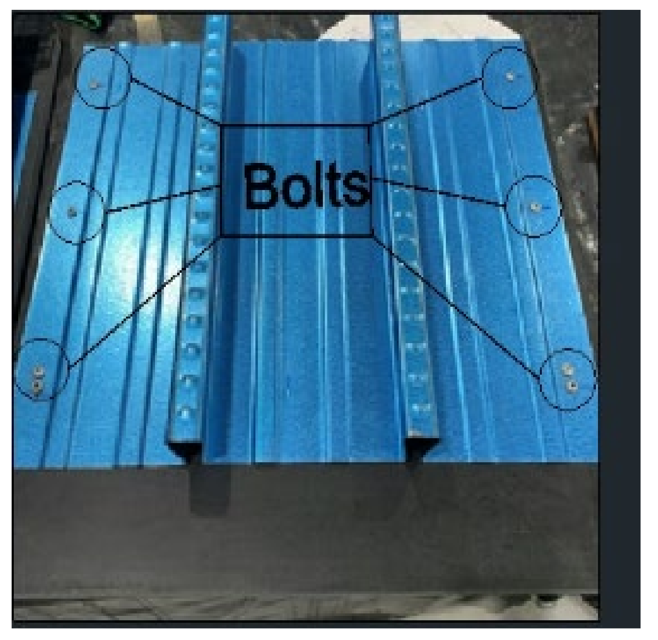
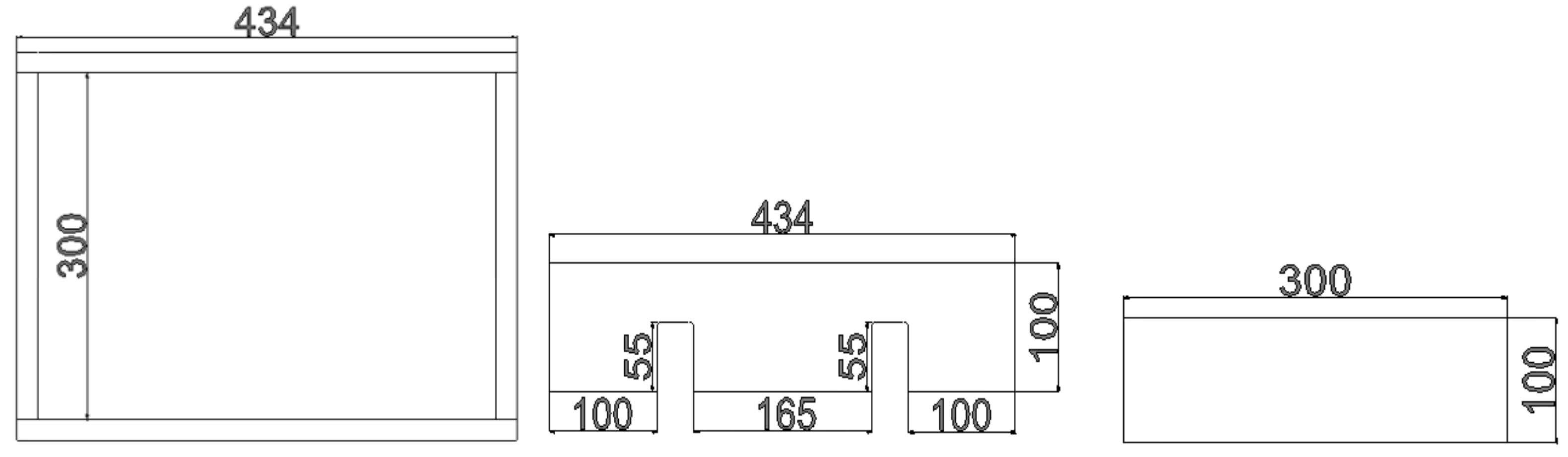
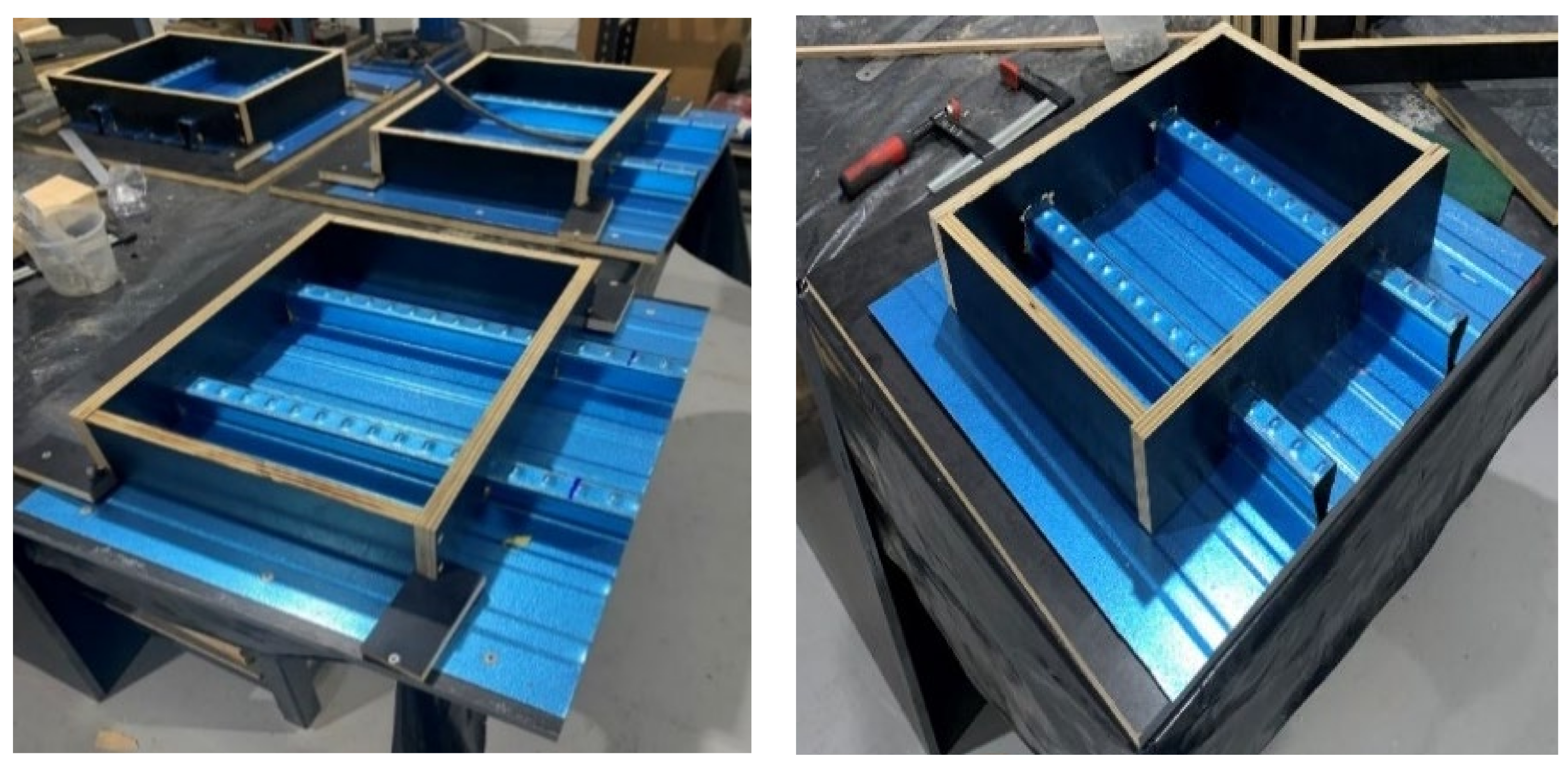
2.2. Specimen Preparation

Six specimens were fabricated for the push test, including four normal concrete specimens and two SCGC specimens. Four normal concrete samples were split into two with a design compressive strength of 40 MPa and two with a compressive design strength of 60 MPa. Table 5 presents the specimen details, where each specimen in the table is annotated with the following abbreviation: type of concrete, design compressive strength and specimen number. It is noteworthy that the embossments provided at the ribs have mild and sharp sides, as shown in Figure 4. According to Jolly and Zubair in 1987 [43], applying pushing force on concrete against the angular side of the embossment provides better bond resistance than against the mild side of the embossment. It is necessary to ensure that the pushing force is applied against the same side of embossment for all specimens to have comparable results, which will be the angular side in this study.
The specimens are designed to have concrete block dimensions of 300 mm (length) × 400 mm (width) × 100 mm (height), as shown in Figure 5. The width of the specimen is 400 mm and is selected to cover two ribs of the profiled sheeting. In a similar manner to the previously conducted studies [39,40,45,53], 300 mm length was chosen to ensure no overturning for concrete, and sufficient bond strength was generated between the profiled sheet and hardened concrete. The adopted thickness of concrete is 100 mm to comply with the minimum thickness requirement of the Australian standards AS/NZS 2327:2017 [69], which is 90 mm. The dimensions of the profiled steel sheet are 500 mm × 450 mm to ensure the availability of sufficient space for test set-up. Each profiled sheet was fixed to a timber plywood sheet, with dimensions of 18 mm × 600 mm × 600 mm by 7–9 bolts, as shown in Figure 6, to ease the concrete casting process and handling procedure during the push test. Form plywood was water jetted to the dimensions, as shown in Figure 7, to form the casting of concrete blocks. Silicon was used to fill the gaps in the formwork to ensure no water leakage happens, especially with SCGC specimens with higher water content than normal concrete. Figure 8 shows the prepared formworks for concrete casting.
Both NC and SCGC mixtures were prepared and cast in the structural laboratory of Deakin University, Australia. A concrete vibrator was used for compacting the NC specimen, while there was no need for vibrator usage with the SCGC specimen, as it is characterised by high flowability. The formwork of the NC specimens was demolded on the following day from casting. The SCGC specimen’s formwork was demolded two days after the casting date to ensure that the SCGC specimens were solid enough. A slump flow test was conducted for each concrete mix to measure its flowability. Nine cylinders were taken from each concrete mixture. Three cylinders for the compressive strength test complied with Australian Standards AS 1012.14:2018 [70], three cylinders used to measure the indirect tensile strength complied with Australian Standards AS 1012.10-2000 [71], and the last three cylinders used for calculating the modulus of elasticity complied with Australian Standards AS 1012.17:1997 [72]. A vibrator table was used on all cylindrical moulds, except the SCGC moulds, to ensure no formation of air bubbles within the mix. The NC cylindrical specimens were placed into a curing water tank for the first seven days after casting at 25 °C temperature, while the SCGC specimens were left to cure under the laboratory temperature. The test results, including the mechanical properties and workability test, are discussed thoroughly in the discussion section.

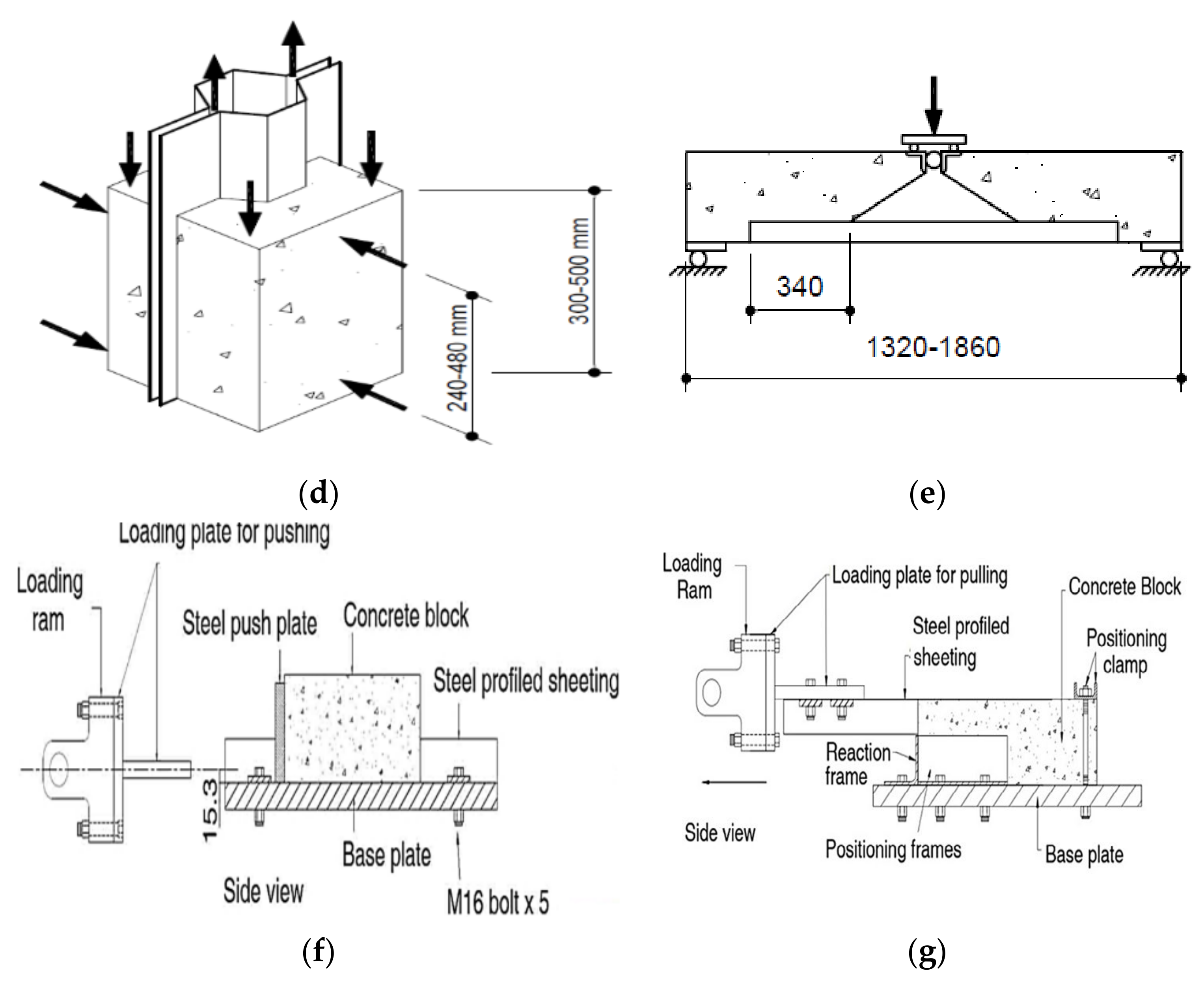
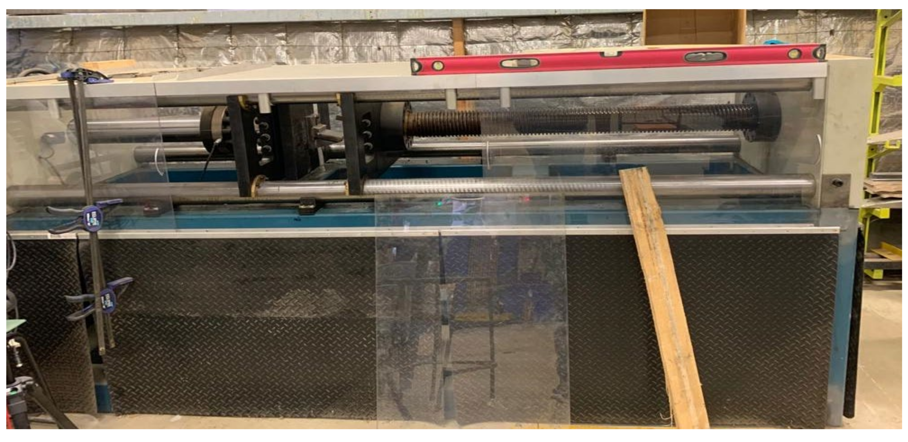
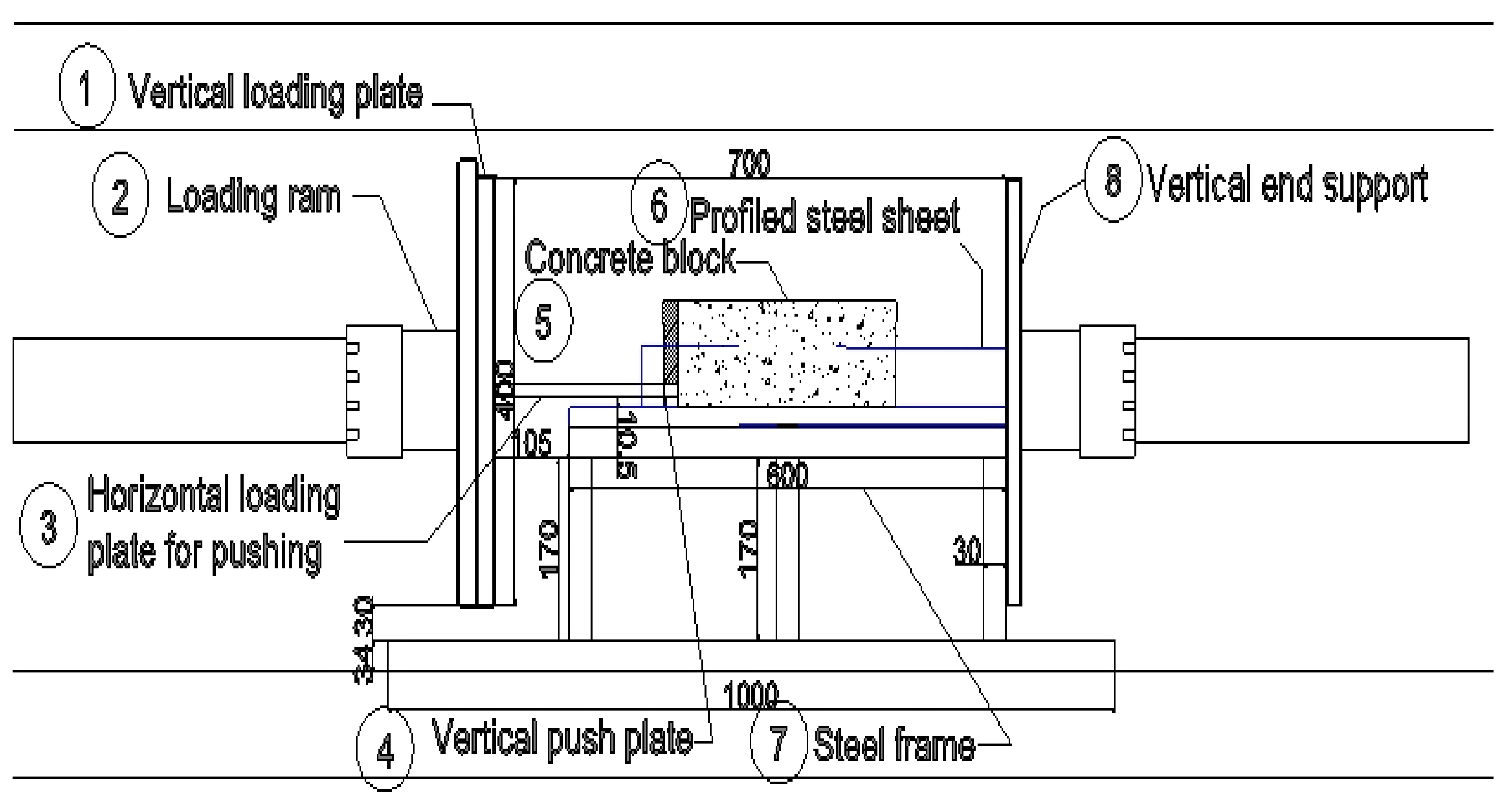
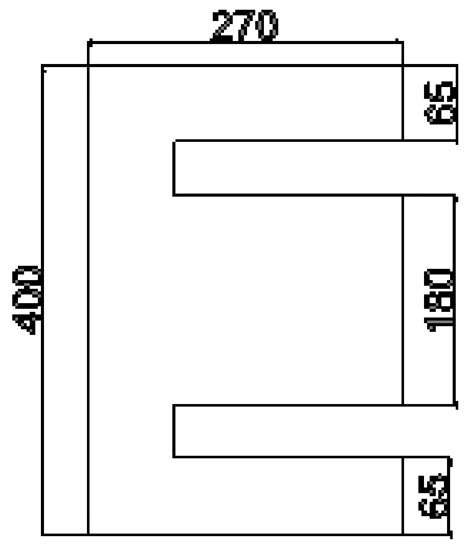
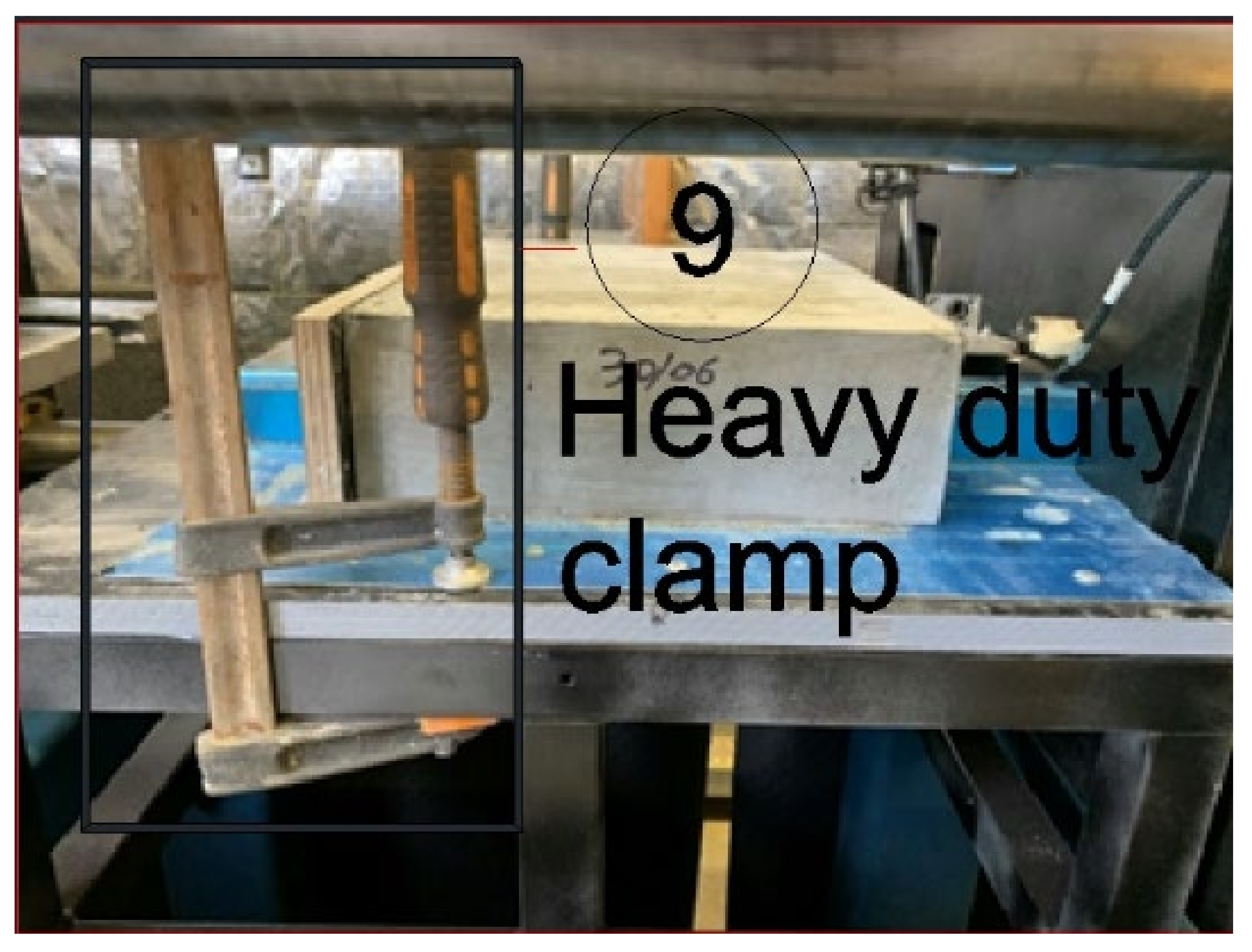
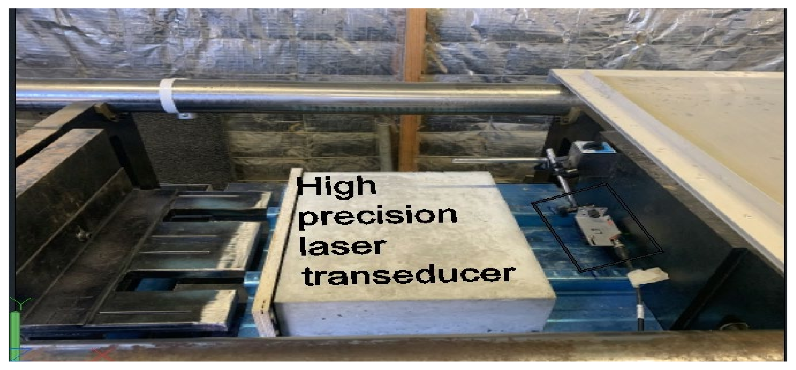
2.3. Test Set-Up and Loading Procedure

A hydraulic horizontal testing frame of 1000 kN capacity, as shown in Figure 9, at Deakin University’s structural lab was used to carry out the push test. The equipment consists of a horizontal hydraulic jack fastened to a rigid frame. The horizontal hydraulic jack is connected to the MTS machine to control the displacement and speed of the applied load over the specimen. It was noticed that the centreline of the vertical loading plate attached to the loading jack was above the machine top frame base by 260 mm, which may cause some inclination if the specimen is not positioned close to the centre level of the vertical press plate. As shown in Figure 10, a structural frame was designed to lift the samples and keep the vertical loading plate’s centerline and the profiled sheet’s centroid aligned. Figure 11 presents a side view of the push test set-up. As shown in Figure 11, a horizontal loading steel plate to apply horizontal force, marked no. 3, was fabricated and directly fixed to the centre of the vertical loading plate, marked no 1. The horizontal loading steel plate’s dimensions, as presented in Figure 12, were designed to evenly distribute force on the concrete side in the longitudinal direction. According to the manufacturer’s design guidelines, the horizontal push plate was pointed at the centroid of the profiled sheet, which was 15.5 mm above the profiled sheet. The horizontal loading steel plate was applied directly on the vertical push plate, marked no 4 in Figure 11, and was positioned ahead of the concrete block. A vertical end steel support, marked no 8 in Figure 11, backed the specimen, and heavy-duty clamps, as shown in Figure 13, were used to attach the sample to the structural lift frame and to ensure no movement occurred during the test.
The mechanism of the push test was to apply a horizontal load on the concrete block to shear it off from the profiled steel sheet. During the testing procedure, a longitudinal shear resistance was developed at the concrete-profiled sheet interface, due to the chemical adhesion property of concrete and mechanical interlock and frictional resistance. A low loading rate of 0.5 mm/min was applied in the displacement-controlled mode to precisely measure the load-slip behaviour of the composite slab.
During the push test, the concrete end slip was measured using a high-precision laser sensor, as shown in Figure 14, to confirm the results obtained from the machine. The displacement results obtained from the MTS machine and the laser sensor were agreed upon.

3. Test Results and Discussions

3.1. Mechanical Properties

Table 6 presents the results obtained from the compressive strength test, indirect tensile strength test, modulus of elasticity and slump flow test for NC40, NC60 and SCGC. The results confirm the compressive design strengths of the various mixes used in this program. According to the EFNARC Guidelines, the self-compacted concrete’s flowability ranges between 650 mm and 800 mm. The flowability of SCGC is 680 mm, and this value lies between the standard range of self-compacted concrete.

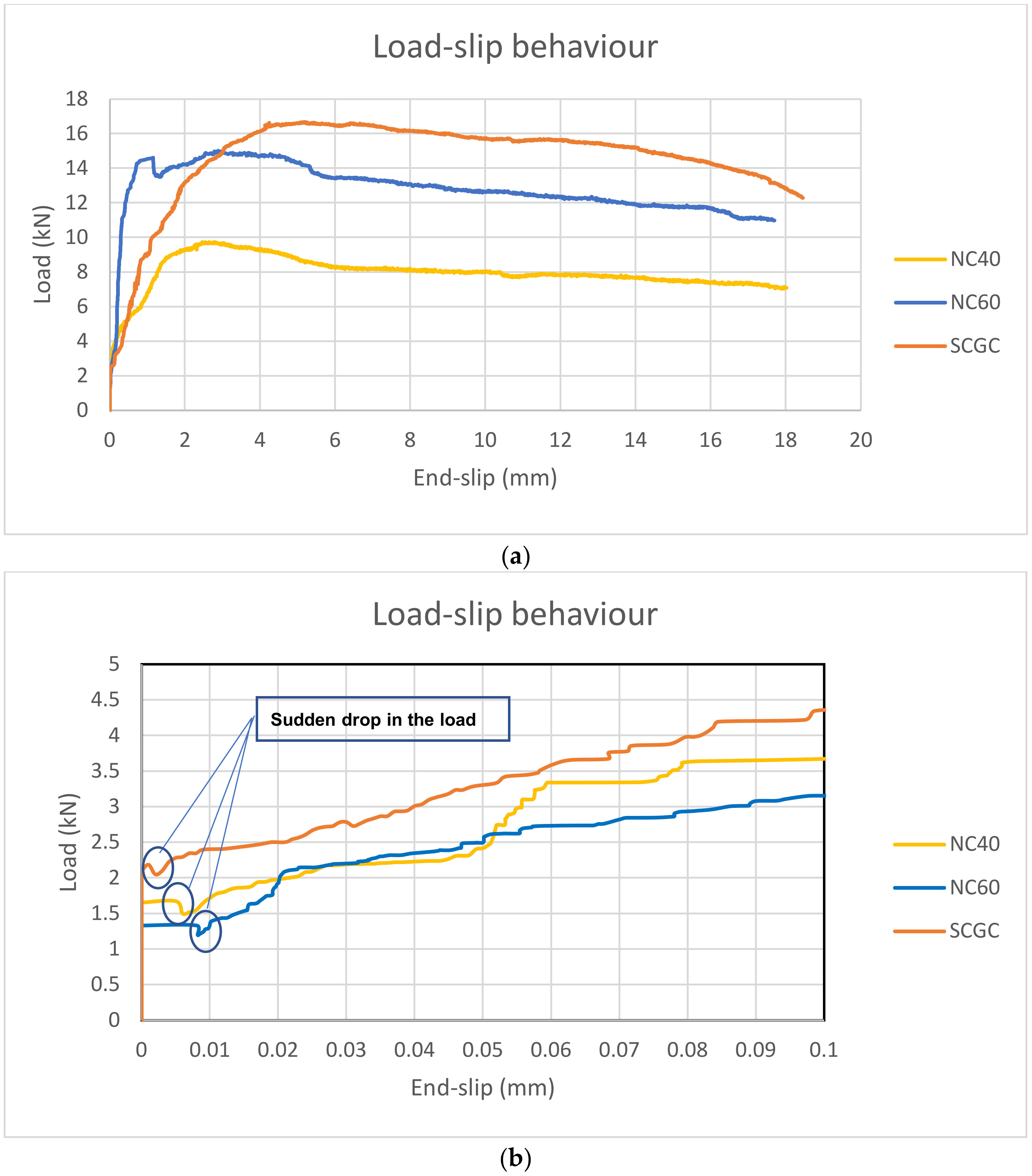
3.2. Bond–Slip Relationship

The applied load and end-slip were continuously recorded, until the composite slab specimen could not withstand any load. A comparative analysis was conducted to investigate the load slip behaviour of the SCGC composite slab compared to the normal concrete composite slab with compressive strength of 40 MPa and 60 MPa, respectively. Table 7 presents the results from the push tests on six specimens that demonstrate chemical adhesion breaking loads, interface connection stiffness, ultimate loads and toughness. The mechanism of shear load transfer in the composite slab system is profoundly dependent on the composite interaction between the profiled steel sheet and the hardened concrete. The concrete chemical adhesion bond and mechanical and frictional resistance developed at the concrete-profiled steel sheet interface are responsible for transferring shear loads to the beam elements. The maximum load concrete can withstand before the chemical break occurs is the chemical adhesion break load. A sudden drop in load happens once the chemical adhesion is broken, followed by a proportional increase between the applied load and end-slip, due to the mechanical interlock and frictional resistance. The interface connection stiffness can be expressed based on the slope of the linear graph drawn up to the ultimate load. The composite slab toughness can withstand inelastic deformation without a rapid deterioration in its ultimate strength. The composite slab toughness can be described as the total area under the load–slip curve to the rupture (failure load). The failure load can be considered 80% of the ultimate load at the descending branch of the load–end slip curve.
Load–end slip curves of NC40, NC60 and SCGC composite slabs are shown in Figure 15. It is to be noted that a cracking sound was heard early at the first recorded end slip during the test at loads that varied between 1 and 2.5 MPa, which indicated that the chemical adhesion bond was broken. NC40 reported a 25% better average chemical bond strength than NC60. On the other hand, SCGC showed a 31% better average chemical adhesion bond than NC40 and 64% better average chemical adhesion bond than NC60, respectively. The higher chemical adhesion bond observed in the SCGC composite slab could be due to the higher moisture content in the mixture that interacted with the binder material and resulted in better flowability and distribution over the profiled sheet contact surface. The findings indicate that the geopolymer binder has better chemical adhesion than normal concrete. It is also possible to interpret that neither compressive nor tensile strength influences the chemical adhesion bond between the profiled sheet and concrete, as NC40 and NC60 have higher compressive strength and tensile strength than SCGC, but a lower chemical adhesion bond.
Once the chemical adhesion bond between concrete block and profiled steel sheet is broken, a sudden drop in load occurs, followed by a gradual increase in the load proportional to the end slip, as shown in Figure 15b. The slip resistance load is attributed to the combined effect of mechanical interlock (embossment) and frictional resistance at the concrete-profiled steel sheet interface. The ascending load–end slip graph slope represents the interface connection stiffness (m). The stiffness of the composite slab is due to the composite interaction between the concrete and profiled steel sheet surface. NC60 specimens have a high average shear connection stiffness value equal to 21.50 MPa, which is approximately five times higher than NC40. SCGC specimens recorded an average shear connection stiffness value of 6.25 MPa, 71% lower than NC60 but 45% higher than NC40. The results indicate that increased compressive strength enhances the shear connection stiffness. However, SCGC specimens with lower compressive strength showed a higher interface connection stiffness than NC40 specimens, which was not expected. As the slip progressed, all standard concrete samples observed a sudden drop in load, indicating that the embossment’s angular side was compressed within the elastic deformation zone and escaped from the indention. Afterwards, the load gradually increases with slip progress, until it approached the ultimate load. Then, the load gradually decreased until the specimen could not withstand any load. Compared to NC specimens, the different load–end slip behaviour can be attributed to the better composite interaction between SCGC and the angular side of the embossments.
NC60 recorded an average ultimate load equal to 15.30 KN at an end slip equal to 3.35 mm. On the other hand, NC40 recorded a 10.26 KN average ultimate load at the relevant slip value equivalent to 2.70 mm. The results showed that NC60 specimens have 49% higher average ultimate strength than NC40. SCGC specimens have 66% higher average ultimate strength than NC40 and 11% higher average ultimate strength than NC60. The higher ultimate strength developed with SCGC specimens compared to NC specimens is due to the lower hardness associated with SCGC, allowing for better composite interaction between SCGC and the profiled steel sheet. The average ultimate load strength of the SCGC specimens was developed at 4.64 mm, which was higher than the NC specimens. The low concrete hardness associated with SCGC allowed the angular side of the embossment to crush into the concrete, causing better shear resistance at the SCGC-profiled sheet interface than the NC specimens.
The composite slab toughness or ductility is the energy capacity that a composite slab can sustain without rapidly losing its strength. The integrated area under the load–slip curve is up to 80% of the ultimate load. The SCGC1 and SCGC2 specimens showed unexpected results, as they recorded 81% higher average toughness compared to NC40 and 16.5% higher average toughness compared to NC60. Compared to NC, the low concrete hardness associated with SCGC allowed for better mechanical interlock and friction between the profiled steel sheet and SCGC.

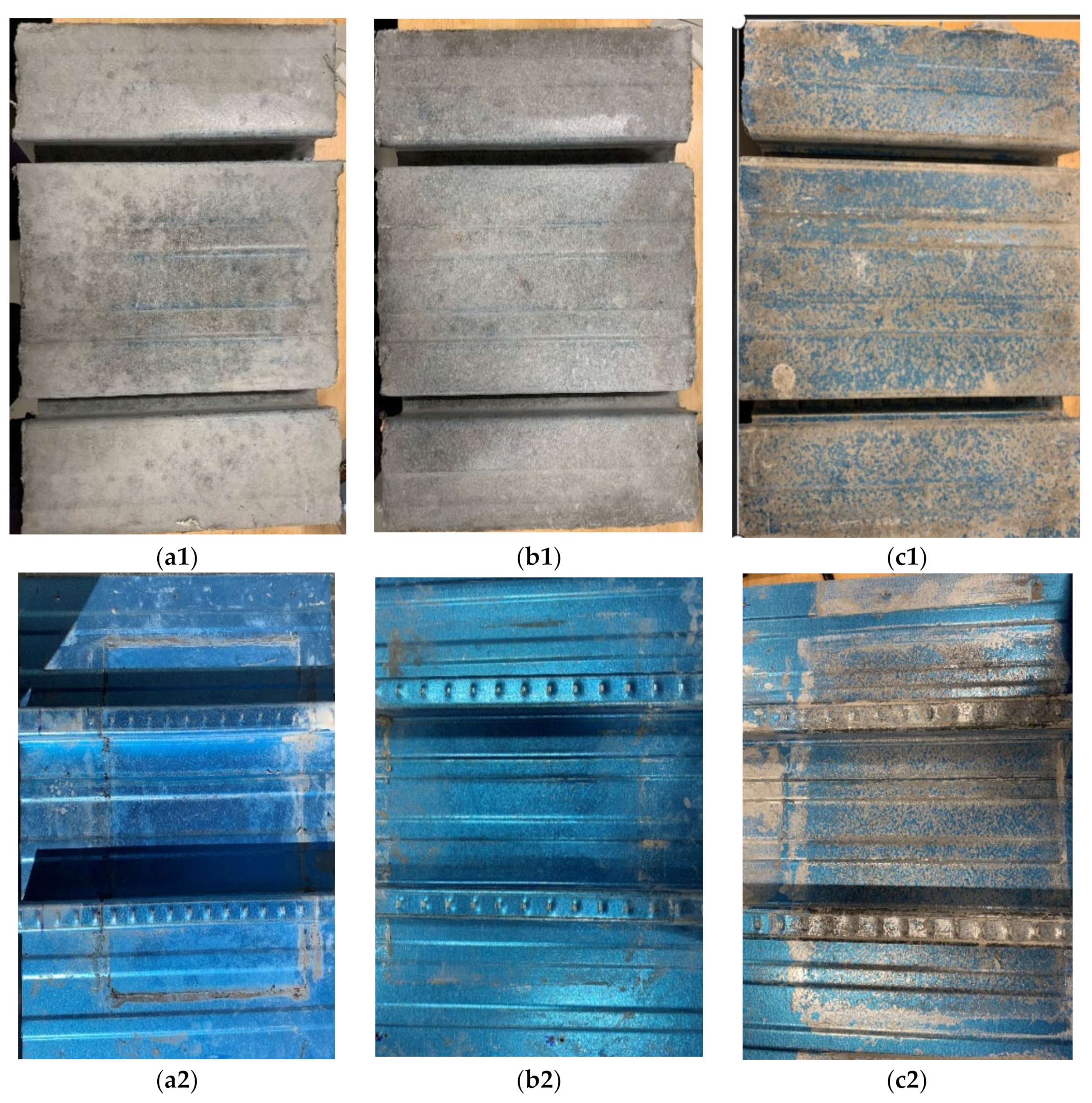
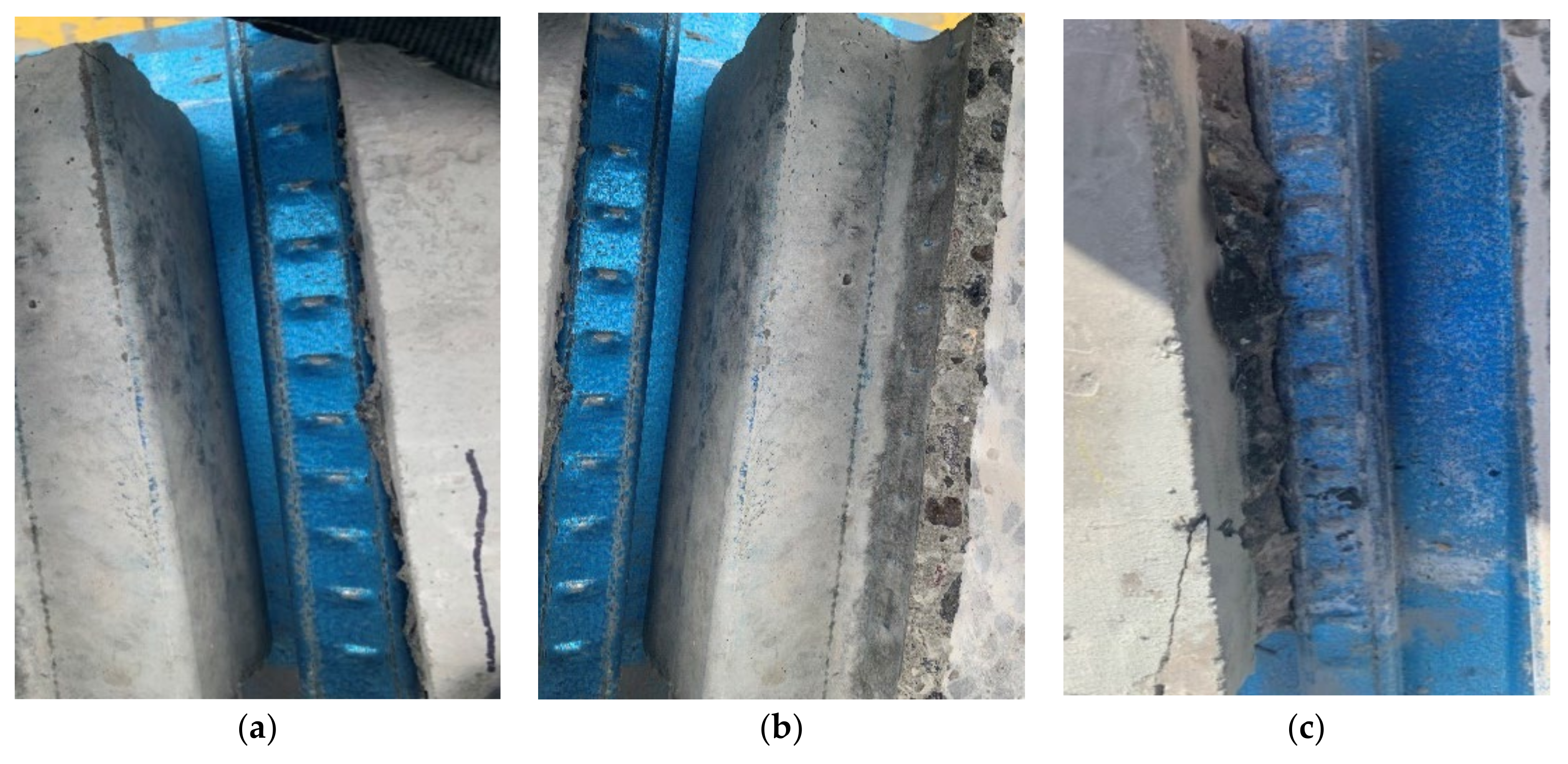
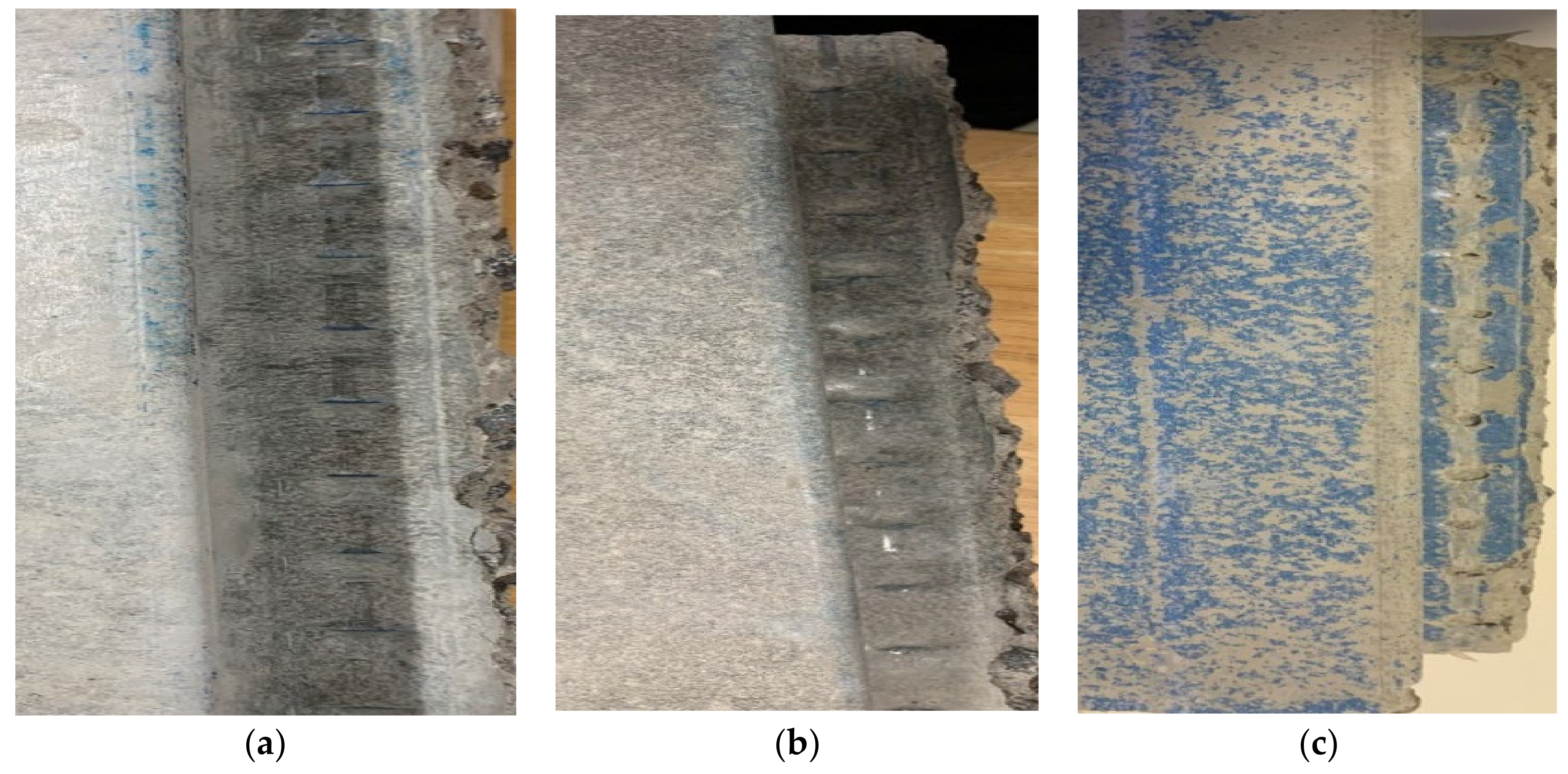
3.3. Visual Observation

After push test completion, the concrete-profiled steel sheet interface of one specimen of each mixture was investigated by separating the concrete block from the profiled steel sheet, as shown in Figure 16. NC40 and NC60 shared the same observations regarding the smooth concrete bottom surface, as shown in Figure 16(a1,b2), with no cracks. In addition, the profiled steel sheet was clean, and no concrete powder was left on the soffit or ribs, as shown in Figure 16(a2,b2). On the other hand, the SCGC specimen showed a different behaviour for the concrete block bottom and profiled steel sheet interface. For the SCGC specimen, the blue zinc coated covering the profiled steel sheet was primarily wiped off the profiled sheet surface, as shown in Figure 16(c2), and printed on the SCGC interface, as shown in Figure 16(c1), which was not observed in the NC specimens. The observed behaviour indicates that SCGC has a better chemical adhesion bond with profiled sheets than NC.
The observed behaviour indicates that SCGC has a better chemical adhesion bond with the profiled sheets than NC. For profound visual observation, a diamond saw machine cut through the concrete from the top to the bottom edge around the ribs for the three specimens, as shown in Figure 17. The aim was to ensure that the voids formed due to the interaction between the embossments and concrete were kept intact and not affected by the saw. A crushed SCGC powder was observed around the profiled sheet embossments, as shown in Figure 17c, which indicates a heavy interaction between SCGC and the embossment during the push test. There was no observed crushed concrete around the embossments in the NC specimens, as shown in Figure 17a,b. Figure 18 shows the indentions developed in the NC40, NC60 and SCGC samples at the concrete embossment interface. A minor groove was formed along the longitudinal path due to the heavy interaction between SCGC and the embossments, as shown in Figure 18c. At the same time, for NC40 and NC60, an imprint was visible, as shown in Figure 18a,b, indicating less interaction between NC and the embossments than the SCGC specimens. The better composite interaction between SCGC and the embossments can be attributed to the lower concrete hardness that SCGC has compared to NC. The lower SCGC hardness allowed the angular side of the embossment to crush a small amount of concrete during the push test and improve the composite interaction between SCGC and the profiled sheet. Once the chemical adhesion is broken and the concrete block slips into the longitudinal rib direction, the concrete block compresses the embossment within the elastic deformation zone. This deformation is fully recovered in the subsequent concrete void. Hence, there was no deformation observed in the embossment after test completion.

4. Conclusions

In summary, small-scale push tests were carried out to investigate the load slip behaviour of SCGC composite slabs compared to NC composite slabs with targeted compressive strengths equal to 40 and 60 MPa. The results obtained from the conducted push tests will help us to understand the composite interaction between re-entrant profiled steel sheets and SCGC and, subsequently, evaluate its efficiency compared to the normal concrete composite slab. The obtained results are summarised as follows:
  • SCGC has a better chemical adhesion bond with profiled steel sheets than normal concrete, confirmed by visual observation and the test results. SCGC showed a 131% better chemical adhesion bond than NC40 and 164% better chemical adhesion bond compared to NC60. It can also be concluded that the chemical adhesion bond between concrete and profiled steel sheets is influenced by neither the concrete compressive strength nor the tensile strength, but by the binder distribution at the concrete-profiled steel sheet interface.
  • The SCGC composite slab has approximately 71% lower shear connection stiffness than the NC60 composite slab, but 46% higher than the NC40 composite slab.
  • The SCGC composite slab developed 66% and 11% higher ultimate strength than NC40 and NC60. In addition, the relevant slip to the maximum load of the SCGC composite slab was higher than that for NC40 and NC60, indicating that the SCGC slab has better resilience than NC40 and NC60.
  • The SCGC slab has higher toughness compared to NC40 and NC60, as a result of the low concrete hardness associated with SCGC, which allowed for better mechanical interlock and frictional resistance between the profiled steel sheet and SCGC, compared to NC.

Author Contributions

Conceptualization, M.H. and R.A.-A.; data curation, M.H.; investigation, M.H.; methodology, M.H.; supervision, B.K. and R.A.-A.; writing—original draft, M.H.; writing—review & editing, B.K. and R.A.-A. All authors have read and agreed to the published version of the manuscript.

Funding

This research received no external funding.

Institutional Review Board Statement

Not applicable.

Informed Consent Statement

Not applicable.

Data Availability Statement

Available on request from authors.

Acknowledgments

The authors would like to acknowledge the support of Deakin University in carrying out the present study. Moreover, the assistance of Leanne Farago, Lube Veljanoski and Michael Shanahan during the experimental phase of the study is gratefully acknowledged.

Conflicts of Interest

The authors declare no conflict of interest.

References

  1. Vieira, P.S.; Horvath, A. Assessing the end-of-life impacts of buildings. Environ. Sci. Technol. 2008, 42, 4663–4669. [Google Scholar] [CrossRef] [PubMed]
  2. Lippiatt, B.C. Bees 4.0: Building for Environmental and Economic Sustainability. Technical Manual and User Guide. 2007. Available online: https://tsapps.nist.gov/publication/get_pdf.cfm?pub_id=860108 (accessed on 8 October 2021).
  3. Turner, L.K.; Collins, F.G. Carbon dioxide equivalent (CO2-e) emissions: A comparison between geopolymer and OPC cement concrete. Constr. Build. Mater. 2013, 43, 125–130. [Google Scholar] [CrossRef]
  4. Law, D.W.; Adam, A.A.; Molyneaux, T.K.; Patnaikuni, I.; Wardhono, A. Long term durability properties of class F fly ash geopolymer concrete. Mater. Struct. 2015, 48, 721–731. [Google Scholar] [CrossRef]
  5. Deb, P.S.; Sarker, P.K.; Barbhuiya, S. Sorptivity and acid resistance of ambient-cured geopolymer mortars containing nano-silica. Cem. Concr. Compos. 2016, 72, 235–245. [Google Scholar] [CrossRef]
  6. Kong, D.L.Y.; Sanjayan, J.G. Damage behavior of geopolymer composites exposed to elevated temperatures. Cem. Concr. Compos. 2008, 30, 986–991. [Google Scholar] [CrossRef]
  7. Hardjito, D.; Wallah, S.E.; Sumajouw, D.M.J.; Rangan, B.V. Factors Influencing the Compressive Strength of Fly Ash-Based Geopolymer Concrete. Civ. Eng. Dimens. 2004, 6, 88–93. [Google Scholar] [CrossRef]
  8. Ma, C.-K.; Awang, A.Z.; Omar, W. Structural and material performance of geopolymer concrete: A review. Constr. Build. Mater. 2018, 186, 90–102. [Google Scholar] [CrossRef]
  9. Duxson, P.; Provis, J.L.; Lukey, G.C.; van Deventer, J.S.J. The role of inorganic polymer technology in the development of ‘green concrete’. Cem. Concr. Res. 2007, 37, 1590–1597. [Google Scholar] [CrossRef]
  10. Van Deventer, J.S.J.; Provis, J.L.; Duxson, P.; Brice, D.G. Chemical Research and Climate Change as Drivers in the Commercial Adoption of Alkali Activated Materials. Waste Biomass Valorization 2010, 1, 145–155. [Google Scholar] [CrossRef]
  11. Nuruddin, M.F.; Qazi, S.A.; Kusbiantoro, A.; Shafiq, N. Utilisation of waste material in geopolymeric concrete. Proc. Inst. Civ. Eng.-Constr. Mater. 2011, 164, 315–327. [Google Scholar] [CrossRef]
  12. Nath, P.; Sarker, P.K. Flexural strength and elastic modulus of ambient-cured blended low-calcium fly ash geopolymer concrete. Constr. Build. Mater. 2017, 130, 22–31. [Google Scholar] [CrossRef]
  13. Rahman, S.K.; Al-Ameri, R. A newly developed self-compacting geopolymer concrete under ambient condition. Constr. Build. Mater. 2021, 267, 121822. [Google Scholar] [CrossRef]
  14. Ariffin, M.A.M.; Bhutta, M.A.R.; Hussin, M.W.; Mohd Tahir, M.; Aziah, N. Sulfuric acid resistance of blended ash geopolymer concrete. Constr. Build. Mater. 2013, 43, 80–86. [Google Scholar] [CrossRef]
  15. Bakharev, T. Resistance of geopolymer materials to acid attack. Cem. Concr. Res. 2005, 35, 658–670. [Google Scholar] [CrossRef]
  16. Sarker, P.K. Bond strength of reinforcing steel embedded in fly ash-based geopolymer concrete. Mater. Struct. 2011, 44, 1021–1030. [Google Scholar] [CrossRef]
  17. Castel, A.; Foster, S.J. Bond strength between blended slag and Class F fly ash geopolymer concrete with steel reinforcement. Cem. Concr. Res. 2015, 72, 48–53. [Google Scholar] [CrossRef]
  18. Zhao, R.; Yuan, Y.; Cheng, Z.; Wen, T.; Li, J.; Li, F.; Ma, Z.J. Freeze-thaw resistance of Class F fly ash-based geopolymer concrete. Constr. Build. Mater. 2019, 222, 474–483. [Google Scholar] [CrossRef]
  19. Luhar, S.; Nicolaides, D.; Luhar, I. Fire resistance behaviour of geopolymer concrete: An overview. Buildings 2021, 11, 82. [Google Scholar] [CrossRef]
  20. Fan, Y.; Yin, S.; Wen, Z.; Zhong, J. Activation of fly ash and its effects on cement properties. Cem. Concr. Res. 1999, 29, 467–472. [Google Scholar] [CrossRef]
  21. Puertas, F.; Martínez-Ramírez, S.; Alonso, S.; Vázquez, T. Alkali-activated fly ash/slag cements: Strength behaviour and hydration products. Cem. Concr. Res. 2000, 30, 1625–1632. [Google Scholar] [CrossRef]
  22. Somna, K.; Jaturapitakkul, C.; Kajitvichyanukul, P.; Chindaprasirt, P. NaOH-activated ground fly ash geopolymer cured at ambient temperature. Fuel 2011, 90, 2118–2124. [Google Scholar] [CrossRef]
  23. Zannerni, G.M.; Fattah, K.P.; Al-Tamimi, A.K. Ambient-cured geopolymer concrete with single alkali activator. Sustain. Mater. Technol. 2020, 23, e00131. [Google Scholar] [CrossRef]
  24. Ardalan, R.B.; Emamzadeh, Z.N.; Rasekh, H.; Joshaghani, A.; Samali, B. Physical and mechanical properties of polymer modified self-compacting concrete (SCC) using natural and recycled aggregates. J. Sustain. Cem.-Based Mater. 2020, 9, 1–16. [Google Scholar] [CrossRef]
  25. Nematollahi, B.; Sanjayan, J.; Shaikh, F.U.A. Synthesis of heat and ambient cured one-part geopolymer mixes with different grades of sodium silicate. Ceram. Int. 2015, 41, 5696–5704. [Google Scholar] [CrossRef]
  26. Bong, S.H.; Nematollahi, B.; Nazari, A.; Xia, M.; Sanjayan, J. Efficiency of Different Superplasticizers and Retarders on Properties of ‘One-Part’ Fly Ash-Slag Blended Geopolymers with Different Activators. Materials 2019, 12, 3410. [Google Scholar] [CrossRef] [PubMed]
  27. Cifuentes, H.; Medina, F. Experimental study on shear bond behavior of composite slabs according to Eurocode 4. J. Constr. Steel Res. 2013, 82, 99–110. [Google Scholar] [CrossRef]
  28. Gholamhoseini, A.; Gilbert, R.I.; Bradford, M.A.; Chang, Z.T. Longitudinal shear stress and bond–slip relationships in composite concrete slabs. Eng. Struct. 2014, 69, 37–48. [Google Scholar] [CrossRef]
  29. Wright, H.D.; Evans, H.R.; Harding, P.W. The use of profiled steel sheeting in floor construction. J. Constr. Steel Res. 1987, 7, 279–295. [Google Scholar] [CrossRef]
  30. Patrick, M.; Bridge, R.Q. Partial shear connection design of composite slabs. Eng. Struct. 1994, 16, 348–362. [Google Scholar] [CrossRef]
  31. Porter, M.L.; Ekberg, C.E., Jr. Compendium of ISU Research Conducted on Cold-Formed Steel-Deck-Reinforced Slab Systems; National Academy of Sciences: Washington, DC, USA, 1978. [Google Scholar]
  32. Oehlers, D.J.; Bradford, M.A. 13-Longitudinal Shear. In Composite Steel and Concrete Structural Members; Oehlers, D.J., Bradford, M.A., Eds.; Pergamon: Oxford, UK, 1995; pp. 326–335. [Google Scholar]
  33. Marimuthu, V.; Seetharaman, S.; Arul Jayachandran, S.; Chellappan, A.; Bandyopadhyay, T.K.; Dutta, D. Experimental studies on composite deck slabs to determine the shear-bond characteristic (m–k) values of the embossed profiled sheet. J. Constr. Steel Res. 2007, 63, 791–803. [Google Scholar] [CrossRef]
  34. Mohammed, B.S. Structural behavior and m–k value of composite slab utilizing concrete containing crumb rubber. Constr. Build. Mater. 2010, 24, 1214–1221. [Google Scholar] [CrossRef]
  35. Youssf, O.; Hassanli, R.; Mills, J.E.; Ma, X.; Zhuge, Y. Cyclic Performance of Steel–Concrete–Steel Sandwich Beams with Rubcrete and LECA Concrete Core. J. Compos. Sci. 2019, 3, 5. [Google Scholar] [CrossRef]
  36. Eltayeb, E.; Ma, X.; Zhuge, Y.; Youssf, O.; Mills, J.E.; Xiao, J.; Singh, A. Structural performance of composite panels made of profiled steel skins and foam rubberised concrete under axial compressive loads. Eng. Struct. 2020, 211, 110448. [Google Scholar] [CrossRef]
  37. Holmes, N.; Dunne, K.; O’Donnell, J. Longitudinal shear resistance of composite slabs containing crumb rubber in concrete toppings. Constr. Build. Mater. 2014, 55, 365–378. [Google Scholar] [CrossRef]
  38. Rana, M.M.; Uy, B.; Mirza, O. Experimental and numerical study of the bond–slip relationship for post-tensioned composite slabs. J. Constr. Steel Res. 2015, 114, 362–379. [Google Scholar] [CrossRef]
  39. Burnet, M.J.; Oehlers, D.J. Rib shear connectors in composite profiled slabs. J. Constr. Steel Res. 2001, 57, 1267–1287. [Google Scholar] [CrossRef]
  40. Yi, O.; Zhuge, Y.; Ma, X.; Gravina, R.J.; Mills, J.E.; Youssf, O. Push-off and Pull-out Bond Behaviour of CRC Composite Slabs—An Experimental Investigation. Eng. Struct. 2021, 228, 111480. [Google Scholar] [CrossRef]
  41. Schuster, R.M. Strength and Behavior of Cold-Rolled Steel-Deck-Reinforced Concrete Floor Slabs; Iowa State University: Ames, IA, USA, 1970. [Google Scholar]
  42. Stark, J.W. Design of composite floors with profiled steel sheet. In Proceedings of the CCFSS International Specialty Conference on Cold-Formed Steel Structures (1971–2018), St. Louis, MO, USA, 1 June 1978. [Google Scholar]
  43. Jolly, C.K.; Zubair, A.K. The efficiency of shear-bond interlock between profiled steel sheeting and concrete. In Proceedings of the International Conference on Steel and Aluminum Structures Composite Steel Structures, Advances, Design and Construction, Cardiff, UK, 8–10 July 1987. [Google Scholar]
  44. Daniels, B.J. Shear Bond Pull-Out Tests for Cold-Formed-Steel Composite Slabs: Rapport D’essais; ICOM; École Polytechnique Fédérale de Lausanne Institut de Statique et Structures: Lausanne, Switzerland, 1988. [Google Scholar]
  45. Patrick, M.; Poh, K. Controlled test for composite slab design parameters. In Proceedings of the IABSE Symposium Brussels, Belgium-Mixed Structures, Including New Materials, Brussels, Belgium, 5–7 September 1990; pp. 227–231. [Google Scholar]
  46. Veljkovic, M. Behaviour and Resistance of Composite Slabs: Experiments and Finite Element Analysis. Comprehensive Summary. Ph.D. Thesis, Luleå Tekniska Universitet, Luleå, Sweden, 1996. [Google Scholar]
  47. Veljkovic, M. Behaviour and Design of Shallow Composite Slab. In Composite Construction in Steel and Concrete IV; American Society of Civil Engineers: Reston, VA, USA, 2002; pp. 310–321. [Google Scholar]
  48. Burnet, M. Analysis of Composite Steel and Concrete Flexural Members that Exhibit Partial Shear Connection. Ph.D. Thesis, University of Adelaide, Adelaide, SA, USA, 1998. [Google Scholar]
  49. Rana, M.M. The Effects of Bond and Anchorage on the Behaviour and Design of Composite Slabs. Ph.D. Thesis, UNSW Sydney, Sydney, NSW, Australia, 2016. [Google Scholar]
  50. Abdullah, R. Experimental Evaluation and Analytical Modeling of Shear Bond in Composite Slabs. Ph.D. Thesis, Virginia Tech, Blacksburg, VA, USA, 2004. [Google Scholar]
  51. Veljkovic, M. Longitudinal shear capacity of composite slabs. In Proceedings of the Nordic Steel Construction Conference, Malmo, Sweden, 19–21 June 1995; pp. 547–554. [Google Scholar]
  52. An, L. Load Bearing Capacity and Behaviour of Composite Slabs with Profiled Steel Sheet. Ph.D. Thesis, Chalmers University of Technology, Goteborg, Sweden, 1993. [Google Scholar]
  53. Holomek, J.; Bajer, M.; Barnat, J.; Schmid, P. Design of composite slabs with prepressed embossments using small-scale tests. Struct. Concr. 2015, 16, 137–148. [Google Scholar] [CrossRef]
  54. Devika, C.; Deepthi, R. Study of flexural behavior of hybrid fibre reinforced geopolymer concrete beam. Int. J. Sci. Res. 2015, 4, 130–135. [Google Scholar]
  55. Kathirvel, P.; Kaliyaperumal, S.R.M. Influence of recycled concrete aggregates on the flexural properties of reinforced alkali activated slag concrete. Constr. Build. Mater. 2016, 102, 51–58. [Google Scholar] [CrossRef]
  56. Visintin, P.; Ali, M.S.M.; Albitar, M.; Lucas, W. Shear behaviour of geopolymer concrete beams without stirrups. Constr. Build. Mater. 2017, 148, 10–21. [Google Scholar] [CrossRef]
  57. Tran, T.T.; Pham, T.M.; Huang, Z.; Chen, W.; Hao, H.; Elchalakani, M. Impact response of fibre reinforced geopolymer concrete beams with BFRP bars and stirrups. Eng. Struct. 2021, 231, 111785. [Google Scholar] [CrossRef]
  58. Huang, Z.; Chen, W.; Hao, H.; Chen, Z.; Pham, T.M.; Tran, T.T.; Elchalakani, M. Flexural behaviour of ambient cured geopolymer concrete beams reinforced with BFRP bars under static and impact loads. Compos. Struct. 2021, 261, 113282. [Google Scholar] [CrossRef]
  59. Rahman, M.; Sarker, P. Geopolymer concrete columns under combined axial load and biaxial bending. In Proceedings of the Concrete 2011 Conference, Dresden, Germany, 8–10 June 2011. [Google Scholar]
  60. Nagan, S.; Karthiyaini, S. A Study on Load Carrying Capacity of Fly Ash Based Polymer Concrete Columns Strengthened Using Double Layer GFRP Wrapping. Adv. Mater. Sci. Eng. 2014, 2014, 312139. [Google Scholar] [CrossRef]
  61. Elchalakani, M.; Karrech, A.; Dong, M.; Ali, M.S.M.; Yang, B. Experiments and Finite Element Analysis of GFRP Reinforced Geopolymer Concrete Rectangular Columns Subjected to Concentric and Eccentric Axial Loading. Structures 2018, 14, 273–289. [Google Scholar] [CrossRef]
  62. Hassaine, N.-E. Shear-Bond Performance of Profiled Steel Sheets when Used as Composite Floor Decks. Masters’s Thesis, University College, Cardiff, UK, 1987. [Google Scholar]
  63. Abdel-Sayed, G.; Temple, M.C.; Madugula, M.K.S. Response of Composite Slabs to Dynamic Loads. Can. J. Civ. Eng. 1974, 1, 62–70. [Google Scholar] [CrossRef]
  64. Daniels, B.J.; Crisinel, M. Composite slab behavior and strength analysis. Part I: Calculation procedure. J. Struct. Eng. 1993, 119, 16–35. [Google Scholar] [CrossRef]
  65. Airumyan, E.; Belyaev, V.; Rumyancev, I. Efficient embossment for corrugated steel sheeting. In Proceedings of the IABSE Symposium on Mixed Structures Including New Materials, Brussels, Belgium, 5–7 September 1990; pp. 137–142. [Google Scholar]
  66. Tremlay, R.; Gignac, P.; Degrange, G.; Rogers, C.A. Variables Affecting the Shear-Bond Resistance of Composite Floor Deck Systems; Missouri University of Science and Technology: Rolla, MO, USA, 2002. [Google Scholar]
  67. AS/NZS 3582.1:2016; Supplementary Cementitious Materials Fly Ash. Standards Australia: Sydney, Australia, 2016; p. 11. Available online: https://infostore.saiglobal.com/en-us/standards/as-nzs-3582-1-2016-101026_saig_as_as_212259/ (accessed on 9 November 2021).
  68. General Purpose Cement-Product Data Sheet; Independent Cement: Melbourne, VIC, Australia, 2017; p. 2.
  69. AS/NZS 2327:2017; Composite Structures-Composite Steel-Concrete Construction in Buildings. Standards Australia: Sydney, Australia, 2017; p. 261. Available online: https://infostore.saiglobal.com/en-us/standards/as-nzs-2327-2017-99192_saig_as_as_208561/ (accessed on 8 January 2021).
  70. AS 1012.14:2018; Methods of Testing Concrete Method for Securing and Testing Cores from Hardened Concrete for Compressive Strength and Mass Per Unit Volume 11. Standards Australia: Sydney, Australia, 2018. Available online: https://infostore.saiglobal.com/en-us/standards/as-1012-14-2018-99136_saig_as_as_208448/ (accessed on 7 December 2021).
  71. AS 1012.10-2000; Methods of Testing Concrete Determination of Indirect Tensile Strength of Concrete Cylinders (‘Brazil’ or Splitting Test) (Reconfirmed 2014). Standards Australia: Sydney, Australia, 2014; p. 5. Available online: https://infostore.saiglobal.com/en-us/standards/as-1012-10-2000-129179_saig_as_as_273253/ (accessed on 2 October 2021).
  72. AS 1012.17-1997; Methods of Testing Concrete Determination of the Static Chord Modulus of Elasticity and Poisson’s Ratio of Concrete Specimens (Reconfirmed 2014). Standards Australia: Sydney, Australia, 1997; p. 13. Available online: https://infostore.saiglobal.com/en-au/standards/as-1012-17-1997-129172_saig_as_as_273232/ (accessed on 12 October 2021).
Figure 1. Small-scale test set-ups (dimensions are in mm). (a) Stark (1987). (b) Burnet (1998). (c) Rana (2016a). (d) Daniels (1988). (e) An (1993). (f) Yi et al. (2021a). (g) Yi et al. (2021a).
Applsci 12 08512 g001aApplsci 12 08512 g001b
Figure 2. Size distribution analysis of fine aggregate used.
Applsci 12 08512 g002
Figure 3. Lysaght dovetailed profiled sheet (dimensions are in mm). (a) 3D section. (b) cross-section.
Applsci 12 08512 g003
Figure 4. Indication of mild and sharp sides of the embossment.
Applsci 12 08512 g004
Figure 5. Specimen (dimensions are in mm).
Applsci 12 08512 g005
Figure 6. A total of 7–9 bolts were used to fix the profiled sheet to timber plywood.
Applsci 12 08512 g006
Figure 7. Detailed dimensions of specimen formwork (dimensions are in mm).
Applsci 12 08512 g007
Figure 8. Specimen’s formwork.
Applsci 12 08512 g008
Figure 9. Hydraulic horizontal testing frame 1000 KN.
Applsci 12 08512 g009
Figure 10. Structural lift frame (dimensions are in mm). (a) Plan view. (b) Side view. (c) 3D view.
Applsci 12 08512 g010
Figure 11. The layout of the push test set-up (dimensions are in mm).
Applsci 12 08512 g011
Figure 12. Horizontal loading steel plate for pushing (dimensions are in mm).
Applsci 12 08512 g012
Figure 13. Heavy duty clamps.
Applsci 12 08512 g013
Figure 14. High precision laser sensor.
Applsci 12 08512 g014
Figure 15. Average load–end slip relationships of the push test specimens. (a) Overall behaviour. (b) Enlarged behaviour.
Applsci 12 08512 g015
Figure 16. Interface of concrete and steel deck of push-off test specimens. (a1) NC40 concrete, (b1) NC60 concrete, (c1) SCGC concrete. (a2) NC40, (b2) NC60, (c2) SCGC.
Applsci 12 08512 g016
Figure 17. Visual observations around embossments. (a) NC40. (b) NC60. (c) SCGC.
Applsci 12 08512 g017
Figure 18. Precise observation of indentions in concrete. (a) NC40. (b) NC60. (c) SCGC.
Applsci 12 08512 g018
Table 1. Physical properties of concrete constituents.
MaterialOdourLoss on Ignition
(%)
Moisture Content
(%)
Relative DensityMelting Point
(°C)
pH
Fly ashNo odour10.12.4>1400--
SlagNo odour----3>120012
Micro fly ashNo odour0.70.012.35----
Anhydrous
sodium
metasilicate
No odour----2.4108812.6
CementNo odour----3.1>1200>11
Table 2. The chemical composition of SCGC binder constituents.
Chemical
Composition
Fly Ash (%)Slag (%)Sodium Metasilicate Anhydrous (%)Micro Fly Ash (%)General Purpose Cement (%) [68]
SiO265.7535.195063.09--
CaO--41.47------
Al2O332.8713.66--32.26--
MgO--6.32------
K2O------0.83--
MnO--0.67------
SO3--2.43------
V2O5--0.20------
TiO21.380.73--1.67--
C4AF--------<97
Na2O----500.41--
CaSO4·2H2O--------2-5
P2O5------0.62--
FeO------1.12--
Others--------0–7.5
Table 3. Mix design for NC40, NC60 and SCGC concrete kg per 1 m3.
MixTargeted Compressive Strength (MPa)Fly Ash
(kg)
Slag
(kg)
Micro Fly Ash
(kg)
Sodium
Metasilicate
(kg)
Cement
(kg)
Fine
Aggregate
(kg)
Coarse
Aggregate
(kg)
SCGC [13]40480360120960763677
NC40400000400632960
NC606000005527301080
Table 4. Profiled steel sheet material properties.
PropertyThickness (mm)Mass (kg/m2)Yield Strength (fy) (Mpa)Minimum Yield Stress (fu)
(MPa)
Coverage
(m2/t)
Cross-Sectional Area
Ash (mm2/m)
Sheeting Elastic Centroid
(mm)
Bondek® profiled steel sheet113.7955075072.50167815.5
Table 5. Tested specimen details.
Specimen No.Concrete Type
NC40NC401Normal concrete
NC402Normal concrete
NC60NC601Normal concrete
NC602Normal concrete
SCGCSCGC1Self-compacted geopolymer concrete
SCGC2Self-compacted geopolymer concrete
Table 6. Concrete mechanical properties.
SCGCNC40NC60
Slump (mm)6809585
Compressive strength (MPa)36.6539.661.45
Indirect tensile strength (MPa)2.533.44
Modulus of elasticity (GPa)151932
Table 7. Average results of load and end slip.
SpecimenPk
(kN)
m
(MPa)
Pu
(kN)
Su
(mm)
Toughness
(J)
NC401.664.3210.262.701424
NC601.3321.5015.303.352193
SCGC2.186.2517.034.642564
Pk is the average load at the first slip-chemical adhesion break load, m is the average interface connection stiffness, and Pu is the average ultimate load that the specimen can withstand (maximum strength). Su is the average end slip associated with Pu.
Publisher’s Note: MDPI stays neutral with regard to jurisdictional claims in published maps and institutional affiliations.

