1. Introduction
China has a vast territory and abundant resources, and is very rich in coal resources. Due to large-scale continuous mining over many years, many goafs have been produced all over the country. With time, the overburden gradually collapses, and the goaf becomes an old goaf. However, as old goafs are widely distributed, more and more highways will inevitably pass through them as construction progresses. Many scholars have carried out research on the problems of highway construction in old goafs, such as the deformation of the roadbed and pavement [
1,
2], the stability of bridges and tunnels [
3,
4,
5], the governance of old goafs under highways [
6,
7], and the detection of old goafs under highways [
8,
9]. For the stability of slopes, most research has focused on: (1) new methods for analyzing slope stability, such a method based on the generalized Hoek–Brown criterion [
10], one based on finite element analysis and superposition of field data [
11], and one method of slope stability prediction based on machine learning [
12]; (2) slope stability analysis of various special soils, such as expansive soil [
13,
14], unsaturated soil [
15], weak soil [
16], etc.; (3) slope stability analysis under various special conditions, such as earthquake conditions [
17], rainfall conditions [
18,
19], etc.; and (4) slope reinforcement measures, such as plant reinforcement [
20,
21], injection of curing liquid reinforcement [
22], etc.
The above scholars have conducted extensive research on highway construction in old mined-out areas and slope stability, but they have not involved the slope stability in mined-out areas. On the stability of mined-out area slopes, Yang et al. [
23] used Flac 3D software to study the influence of underground mined-out areas on slope stability based on strength reduction theory and elastic–plastic mechanics. The results showed that when the sliding surface crossed the mined-out area, it would seriously affect the stability of the slope, but when the mined-out area was above and below the sliding surface, it had little influence on the stability of the slope. To study the influence of mining on the stability of slopes with different dip angles, Fan et al. [
24] analyzed the displacement and deformation of slopes with different dip angles based on Flac 3D numerical simulation. The results show that the larger the dip angle of slopes is, the greater the mining influence and displacement will be. To explore the influence of mined-out areas on slope stability, Wang et al. [
25] analyzed the slope stability under different mining conditions based on Midas GTS numerical simulation. The results showed that the slope stability gradually decreased with the mining of coal seams. To explore the slope instability process of the multilevel mining effect, Zhang et al. [
26] analyzed the local rock mass damage, failure, and instability process in the multilevel slope-mining process based on RFPA finite element software. The results show that the continuous mining of multilevel slopes is mainly caused by local instability under the influence of time and space effects. To explore the influence of the coal mine goaf on the stability of the nearby ground slope, Yang et al. [
27] analyzed the deformation and failure of mining slopes under the influence of new and old goafs based on Midas GTS numerical simulation. The results show that the stability coefficient of the new goaf slope is higher than that of the old goaf slope.
According to the above analysis, some scholars have studied the slope stability of old mined-out areas, but the research is mostly directed on the influence of coal mining on existing slope stability (that is, mined-out areas are new; existing slopes are not newly excavated slopes). Although some scholars have studied the influence of old mined-out areas on slope stability, they only involve situations where the old mined-out areas are located in bedrock (far away from the slope surface), but have not conducted any research on situations where there are old mined-out areas near the slope surface. Because of the cutting slope formed by excavation, when one or more positions of the cutting slope contains a goaf collapsed roadway or collapsed mining face, the stability of the slope excavation is affected and uncertain. Based on this, this paper combines the excavation of a cutting slope in section K1644 + 720–K1644 + 860 of the Jimu Highway Reconstruction and Extension Project, analyzes the stability of cutting slope excavation and the reasonable reinforcement scheme under the influence of an old goaf by Midas GTS, and applies it to the actual project to verify the accuracy of the analysis results. The rest of this paper is structured as follows:
Section 2 introduces the general situation of cutting slope excavation and different excavation schemes;
Section 3 introduces the rock mechanics parameters of the slope numerical model, the calculation method of the slope stability, and the establishment process of the slope model;
Section 4 introduces the slope stability of different excavation schemes and the reasons that affect the slope stability;
Section 5 introduces the reasonable reinforcement scheme of the slope and applies it to the actual project for verification;
Section 6 introduces the discussion of the novelty of the research content, the research results, and the shortcomings.
Section 7 introduces the research conclusion of this paper.
2. Project Overview
The K1644 + 720–K1644 + 860 section of the Jimu Highway reconstruction and expansion project is located in Jixi City, Heilongjiang Province. The original form of the slope is a bedrock mountain, and the underlying coal seam has a goaf and collapsed area. The road section is 140 m long and about 40 m high, with an original slope of about 15° and a slope of 143°. The slope is mainly composed of strongly weathered sandstone, moderately weathered sandstone, and moderately weathered shale. The reconstructed and expanded highway passes through deep cutting. After excavation, the left subgrade will form a high bedrock slope with a maximum excavation depth of 34 m. There are six slopes in total, and each slope is equipped with a 2 m-wide platform. The specific location of the project and the overall map of the cutting slope are shown in
Figure 1.
By means of engineering geological survey and engineering geological exploration, we found that there are the following goaf collapsed areas on the cutting slope:
The K1644 + 790–K1644 + 840 section has a collapsed mining face 20 m from the left; the K1644 + 810–K1644 + 840 section has a goaf collapsed roadway under the right subgrade; the K1644 + 780–K1644 + 860 section has a goaf collapsed roadway parallel to the road 120 m from the left; and the K1644 + 720–K1644 + 830 section has a goaf collapsed roadway parallel to the road 65 m from the left.
Table 1 shows the situation of the goafs and collapsed areas of the cutting slope.
During the excavation stability analysis, the most representative K1644 + 800 slope section in the mileage section was selected. The maximum excavation depth of the pile in this section was 25 m, and the maximum excavation depth of the left side slope was 34 m. According to the geological survey report combined with similar engineering experience, the slope can be divided into six levels of excavation, and three excavation schemes were proposed, as shown in
Table 2. The excavation lines and engineering geological conditions of each scheme are shown in
Figure 2.
In the above picture, the horizontal distance from the No.1 collapsed roadway to the excavation slope toe is −120 m, and the vertical distance is −12 m. The No.2 collapsed roadway has a horizontal distance of −65 m and a vertical distance of −5 m from the excavation slope toe, and is located below the top of the slope. The No.3 collapsed roadway is 20 m horizontally from the excavation slope toe and has a vertical distance of −2 m.
3. Establishment of Slope Finite Element Model
3.1. Rock Mass Mechanical Parameters of Slope
The main rock layers of the slope include weathered sandstone, weathered shale, and collapsed coal seams. The rock mass mechanical parameters of the slope model were set according to the laboratory test parameters of rock mass mechanics in the actual project. The parameters of each rock layer are shown in
Table 3.
3.2. Slope Stability Calculation Method
The slope stability analysis method adopts the strength reduction method. In this method, the strength parameters
c and tan
φ of the rock and soil mass are continuously reduced until the soil mass is destroyed, and the final reduced ratio
is the slope stability coefficient.
In the formula, is the cohesion before and after the strength reduction, and is the internal friction angle before and after the strength reduction.
When calculating the slope deformation of the model, the Mohr–Coulomb criterion needs to be followed. When the shear stress exceeds the shear stress of the rock and soil mass determined by internal friction and cohesion, the rock and soil mass will produce shear failure. The formula for calculating shear stress
is as follows:
In the above formula, is the shear stress, is the maximum principal stress, and is the minimum principal stress.
3.3. Slope Model Parameter Analysis
Whether the parameters of the finite element model are set reasonably or not will probably affect the calculation results of slope stability, and even affect the judgment of slope stability. To establish a reasonable finite element analysis model and ensure the accuracy of the analysis in the fourth and fifth chapters of this paper, the models shown in
Table 4,
Table 5,
Table 6 and
Table 7 are established concerning the engineering geology cross section to analyze the influences of boundary range, mesh size, and boundary conditions on the calculation results of slope stability.
Table 4 shows the models of different boundary ranges, with the mesh size of 1 m, the normal constraint on the side, and the fixed constraint on the bottom.
Table 5 shows the models of different slope mesh sizes, with the model range of X = 240, and Y = 100, with a normal constraint on the side and a fixed constraint on the bottom.
Table 6 shows the models of different bedrock mesh sizes. The range of the model is X = 240, Y = 100, with a normal constraint on the side and a fixed constraint on the bottom.
Table 7 shows the models of different boundary conditions. The mesh size is 1 m, the model range is X = 240, Y = 100, and the side faces are constrained by normal direction.
The above model is calculated, and the calculation results are shown in
Table 8. As can be seen from
Table 8, in this finite element model, the model range and the size of the slope mesh will affect the calculation results of the slope stability coefficient, while the size of the bedrock mesh and the boundary conditions will not affect the calculation results. On the influence of boundary range, with the continuous expansion of the range, when X > 210 m and Y > 85 m, the slope stability coefficient tends to be constant; on the influence of slope mesh size, with the gradual refinement of the size, when the slope mesh size is less than 1 m, the slope stability coefficient tends to be constant.
3.4. Slope Model Establishment
According to the results of parameter analysis of the slope model in
Section 3.3, a finite element slope excavation model is established, and the model size is shown in
Figure 3. The length of the top of the model slope is 67.4 m–100.8 m (excavation scheme No.3–excavation scheme No.1), and the height of the slope is 36.7 m–32.5 m (excavation scheme No.3–excavation scheme No.1); the distance between the upper and lower boundaries of the slope model is 85 m, and the distance between the left and right boundaries of the slope model is 210 m. The model size conforms to the reasonable slope finite element model size proposed by Academician Yingren Zheng [
28]. In the calculation, rock and roadway loose rock are regarded as isotropic and locally homogeneous materials, and the Mohr–Coulomb yield criterion is adopted as the constitutive model of yield function and plastic potential function in model calculation. When meshing, the upper boundary of the model is divided by 1 m unit length and 1 m–3 m linear gradient, the excavated slope is divided by 1 m unit length, the slope angle to the right boundary is divided by 1 m–3 m linear gradient, the left and right boundaries are divided by 3 m unit length, and the slope bottom is divided by 3 m unit length. The density of the mesh is from dense to sparse from the middle of the excavation line to the boundary of the model, and the unit type is triangle + quadrilateral. The schematic diagram of the divided mesh model is shown in
Figure 4. The left and right boundaries of the model adopt normal constraints, the bottom boundary adopts fixed constraints, and the top boundary is free. Constrain the initial displacement, consider the slope stability analysis under the condition that the initial stress field is self-weight, activate the self-weight of the model and the rock material during the analysis, set the stress analysis construction stage and the calculation convergence criterion, and finally add the SRM condition of slope stability for analysis, and obtain the calculation results. The acceleration of gravity is 9.8 m/s
2, and the convergence criterion of calculation is set to terminate when the convergence error is less than the fixed value of 10
−6 and the maximum number of iterations exceeds 1000.
The setting of rainfall conditions: According to the weather and hydrological data in this area, the rainfall condition is set as heavy rainfall of 200 mm for 24 h. According to the rainfall conditions, the corresponding surface flow is applied to the model. According to the project data and the initial groundwater level, nodal heads are added to the left and right boundaries of the model, and the lower boundary is regarded as the impermeable boundary, and the surface is regarded as the rain-permeable boundary.
4. Slope Excavation Stability Analysis
4.1. Slope Stability Analysis of Different Excavation Schemes
During the simulation, the deformation in all directions of the original working condition was first cleared so the model was in a state of in situ stress equilibrium, to ensure that the subsequent deformation would be completely caused by the excavation of the slope.
4.1.1. Scheme Comparison and Selection
According to the requirements of Code for Design of Highway Subgrade JTG D30-2015, normal working conditions and rainfall conditions should be considered when conducting slope stability analysis. The safety factor is 1.3 under normal conditions and 1.2 under rainfall conditions [
29]. The numerical simulation results of the slope stability coefficient of each excavation scheme under normal working conditions are shown in
Figure 5a.
Figure 5b–d show the comparison of the numerical simulation results of the slope stability coefficient between the normal conditions and the rainfall conditions of each excavation scheme.
According to the slope stability evaluation standard [
30] in the Technical Code for Building Slope Engineering GB 50330-2013, the analysis of
Figure 5a shows that the stability coefficient of the sixth-grade slope after excavation in the first scheme is 0.95 under normal working conditions, and it is in an unstable state. The stability coefficient of the second scheme is 1.04 after the excavation of the sixth-grade slope, which is in an unstable state. In the third scheme, the stability coefficient is 2.15 after the sixth-grade slope is excavated, and it is always in a stable state during the excavation process.
According to the analysis of
Figure 5b–d, the stability coefficients of each scheme are reduced under rainfall conditions. After the excavation of the fifth-level slope under the rain condition of Scheme No.1, the stability coefficient changed from 1.03 in the normal condition to 0.99 and changed from the under-stable state to the unstable state, and from the sixth-level excavation in an unstable state to the fifth-level excavation in an unstable state. After the fifth-grade slope was excavated under the rainfall condition of Scheme No.2, the stability coefficient changed from 1.1 in the normal condition to 1.05 and changed from the basic stable state to the under-stable state, and from the sixth-level excavation in an under-stable state to the fifth-level excavation in an under-stable state. After the excavation of the sixth-grade slope under the rainfall condition of Scheme No.3, the stability coefficient changed from 2.15 in the normal condition to 2.06, which is still in a stable state.
From the above analysis, it can be seen that the overall stability of Scheme No.1 becomes worse after the excavation of the fourth-grade slope, the overall stability of Scheme No.2 becomes worse after the fifth-grade slope is excavated, and the overall stability of Scheme No.3 is always better after the slope is excavated. Therefore, Scheme No.3 is the best excavation scheme. However, since the scope of land acquisition for this project has been approved and no new land can be occupied, Scheme No.3 cannot be implemented. The slope stability of Scheme No.2 is significantly greater than that of Scheme No.1, and the number of excavation works does not increase significantly. Therefore, it is finally proposed to adopt Scheme No.2 for excavation.
4.1.2. Scheme No.2 Plastic Zone Analysis
The change in the plastic area of the slope during the excavation process can reflect the stability of the slope. To further analyze the slope stability of the proposed scheme, a numerical simulation of step-by-step excavation was carried out on the slope of Scheme No.2, and the change in the plastic zone is shown in
Figure 6.
Through the analysis of
Figure 6a,b, we found that after the first-class excavation, the slope plastic zone calculated by Midas GTS does not belong to the slope formed by the excavation, but belongs to the original slope. Instead, the calculation of the plastic zone formed by the excavation slope starts after the second-class slope excavation. This is because Midas GTS only calculates the stability factor of the most dangerous slope when calculating the stability factor of a model with multiple slopes. However, the stability coefficient of the excavation slope formed after the first-class excavation was larger than that of the original slope, which is the most dangerous slope. The stability coefficient of the excavated slope formed after the second-class excavation was smaller than the original slope, and the excavated slope is the most dangerous.
Based on
Figure 6c–f, we found that there was an obvious relaxation deformation zone when the slope was excavated to the fourth-class slope. With the increase in the excavation depth, the scope of the relaxation deformation zone was further expanded, and the relaxation deformation zone developed into a potential plastic run-through zone after the sixth excavation. After the sixth-class excavation, the potential landslide shear exit appeared at the location of the collapsed mining face.
Combined with the analysis of Scheme No.2 in
Figure 5, the stability coefficient of the slope body gradually decreased from 3.3 to 1.04 under normal conditions with the increase in excavation depth, and the stability coefficient of the slope body decreased from 3.2 to 1.01 under rainfall conditions. The overall stability of the slope body was good when the excavation reached the fourth class. When the excavation reached the fifth class, the overall stability decreased, and the stability changed from stable to less stable, indicating that reinforcement measures needed to be taken.
4.2. Analysis of the Influence of the Goaf Collapsed Area
To quantitatively analyze the influence of a collapsed area in three collapsed roadways and one collapsed mining face on the slope stability coefficient, in the process of numerical simulation, the control variable method was adopted. We replaced the material of one of them with the material of a similar soil layer, keeping other conditions unchanged, and still adopted Scheme No.2 for step-by-step slope excavation. By comparing the change in the slope stability coefficient during the excavation process, the influence of the collapsed roadway or collapsed mining on the slope stability could be evaluated.
4.2.1. Analysis of the Impact of the Collapsed Roadway
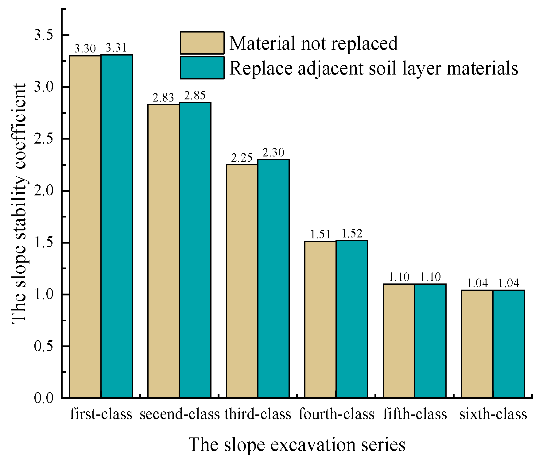
To quantitatively analyze the influence of the No.1 collapsed roadway on the slope stability coefficient, after replacing the materials of the No.1 collapsed roadway with medium weathered shale, and keeping other conditions unchanged, the slope was excavated step by step, adopting Scheme No.2. The comparison between the slope stability coefficient after excavation and that before replacing materials is shown in
Figure 7.
Comparing the stability coefficient of each class of slope excavation after changing the material of the No.1 collapsed roadway to that before changing the material, we found that the existence of the No.1 collapsed roadway only had a slight impact on the stability of the slope excavation from first-class to fourth-class, while other classes of excavation were not affected by the No.1 collapsed roadway. Therefore, the No.1 collapsed roadway will not affect the overall safety of the slope.
We repeated the above operation for collapsed roadway No.2 and collapsed roadway No.3, and the results were similar to those for collapsed roadway No.1.
4.2.2. Analysis of the Impact of the Collapsed Mining Face
To quantitatively analyze the influence of the collapsed mining face on the slope stability coefficient, after the materials of the collapsed mining face of the slope were replaced medium weathered shale, the slope was excavated step by step, adopting Scheme No.2. The comparison of the slope stability coefficient after excavation with that before replacing the materials is shown in
Figure 8.
Comparing the stability coefficient of each class of slope excavation after changing the materials of the collapsed mining face with the results before changing the materials, we found that the existence of the collapsed mining face had little influence on the stability of the first class of slope excavation, but it had a great influence on the stability of the second class to the sixth class of slope excavation. The concrete situation is as follows: the slope stability coefficient increased by 0.02 after the first-class excavation. After the second-class excavation, the stability coefficient increased by 0.25. After the third-class excavation, the stability coefficient increased by 0.53. After the fourth-class excavation, the stability coefficient increased by 0.91. After the fifth-class excavation, the stability coefficient increased by 1.03. After the sixth-class excavation, the stability coefficient increased by 0.91.
Through the analysis of the change in slope stability coefficient after changing the materials in the abovementioned collapsed mining face, we found that the existence of the collapsed mining face was the main factor affecting the slope stability. Because of the existence of the collapsed mining face, the slope stability coefficient decreased to 1.1 after the fifth-class excavation. The reason for this was that after the fifth-class excavation, the collapsed mining face was exposed to the side slope (as shown in
Figure 9). When the upper and lower layers are hard rocks, the collapsed mining face is equivalent to the existence of the weak rock stratum, which turns into the potential sliding face of the slope, resulting in the rock mass above the collapsed mining face sliding downward along the potential sliding face of the side slope under its weight.
4.2.3. Sensitivity Analysis of Material Parameters in Collapsed Mining Face
The sensitivity analysis method is an uncertainty analysis method, which studies the degree of influence of a factor change on one or a group of key indicators from the perspective of quantitative analysis. Its essence is to explain the size law of key indicators affected by these variables by changing the values of related variables one by one. The sensitivity calculation formula is as follows:
In the above formula, is the relative change rate of the slope stability coefficient corresponding to the influencing factor ; is the relative change rate of influencing factor . The larger the is, the greater the sensitivity of the influencing factor is, and the greater the influence of this factor on slope stability.
From the analysis in
Section 4.2.2, it can be seen that the existence of the collapsed mining face is the main reason that affects the stability of the slope. According to the material parameters of rock mass in the collapsed mining face, the models shown in
Table 9,
Table 10,
Table 11 and
Table 12 are established, respectively, to analyze the sensitivity of material parameters such as elastic modulus, cohesion, internal friction angle, and bulk density to assess the relative importance of input variables of rock mass material parameters.
The above different material parameter models are calculated, and the other parameters remain unchanged during the calculation. The calculation results are shown in
Table 13. It can be seen from the table that the cohesion, internal friction angle, and unit weight will affect the calculation results of the slope stability coefficient among the material parameters of the slope collapsed mining face, while the elastic modulus of the rock mass has little effect on the calculation results.
According to the sensitivity calculation formula, the sensitivity of elastic modulus, cohesion, internal friction angle, and unit weight is calculated, and the calculation results are shown in
Table 14. According to the calculation results, among the four material parameters, the sensitivity relationship is internal friction angle > cohesion > unit weight > elastic modulus; that is, the influence of internal friction angle, cohesion, unit weight, and elastic modulus of the collapsed mining face on slope stability decreases in turn. Within the normal fluctuation range, the greater the internal friction angle and cohesion of the collapsed mining face, the more favorable it is for slope stability, and the smaller the unit weight of the collapsed mining face, the more favorable it is for slope stability.
5. Slope Reinforcement Analysis
To prevent landslides during and after slope excavation, according to the selected safety factor, the sliding force was calculated by the transfer coefficient method, and according to the magnitude of the sliding force, we planned to reinforce the slope by setting the anchor cable frame. The length of the anchor cable was 25 m, the length of the anchorage section was 10 m, the design load was 600 kN, the inclination angle was 25°, and two anchor cables were set for each grade of the slope.
Considering the anchor cable structure, this paper used the contact between the rock and anchor cable and the method of assigning value to truss to simulate the reinforcement effect of the anchor cable, and used the embedded truss element in the software to simulate the anchor cable.
For the frame structure, the beam element was used to simulate the frame, and the reinforcement effect was realized by the rigid connection between the frame and the rock mass. The elastic model was adopted for the constitutive model of the anchor cable frame.
A reasonable anchor cable frame-setting scheme can not only enhance the stability of the slope and prevent the slope from collapsing, but also save on cost. Based on the relevant engineering experience, and referring to the analysis results in
Section 4.2, two anchor cable schemes were proposed to treat the slope, as shown in
Table 15. The first scheme was the traditional reinforcement method combined with engineering experience, which involved excavating the slope step by step and strengthening it step by step. The advantage of this method is that it can greatly improve the stability of the slope after construction and completion, and the disadvantage is that when the slope length is too large, the engineering requirements will be greatly increased. The second scheme refers to the analysis results in
Section 4.2 and considers that the slope collapsed mining face is the main reason for the instability of the slope after excavation. Therefore, only the third-class and fourth-class slopes near the slope collapsed mining face were reinforced. The finite element models of the two reinforcement schemes are shown in
Figure 10, and the numerical simulation results are shown in
Figure 11.
In Scheme No.1, in the process of slope excavation, the slope was excavated and reinforced step by step. Compared with the unreinforced slope after excavation, the stability coefficient of each slope was improved as follows: the stability coefficient of the first-class slope increased by 1.4. The stability coefficient of the second-class slope increased by 1.14. The stability coefficient of the third-class slope increased by 1.25. The stability coefficient of the fourth-class slope increased by 1.79. The stability coefficient of the fifth-class slope increased by 2.03. The stability coefficient of the sixth-class slope increased by 1.64.
In Scheme No.2, in the process of slope excavation, only the third-class and fourth-class slopes were reinforced with anchor cable frames. Compared with the unreinforced slopes after excavation, the stability coefficient of the third-class to sixth-class slopes improved as follows: The stability coefficient of the third-class slope improved by 0.6. The stability coefficient of the fourth-class slope increased by 1.3. The stability coefficient of the fifth-class slope increased by 1.56. The stability coefficient of the sixth-class slope increased by 1.43.
Through the above quantitative analysis, it can be seen that the two reinforcement schemes can greatly improve the stability coefficient of the slope during and after excavation, and the slope is in a stable state. Further analysis shows that in the process of slope excavation, although the increase in the stability coefficient of Scheme No.1 is obviously greater than that of Scheme No.2, the difference between the stability coefficients of Scheme No.1 and Scheme No.2 is only 0.21 after the slope excavation is completed, and the stability coefficients of the two schemes are both greater than 2.0, ensuring that the slope is in a stable state. This shows that although the treatment effect of Scheme No.2 is not as good as that of Scheme No.1, it can still greatly improve the stability coefficient of the slope after excavation so that the stability of the slope can meet the engineering needs. Therefore, it is reasonable and feasible to adopt the second scheme to reinforce the slope.
Through the above analysis, Scheme No.2 was finally adopted to treat the slope. The construction design is shown in
Figure 12, and
Figure 13 shows the site anchor cable construction drawing. After Scheme No.2 was adopted for reinforcement, through a one-year observation, the slope stability was found to be good, and there were no engineering-related geological disasters, such as landslides.
6. Discussion
The novelty of the excavation stability of the old mined-out area cutting slope studied in this paper lies in analyzing the influence on the slope stability when the mined-out collapsed part is near the cutting slope due to cutting excavation, and the analysis of the reasonable slope reinforcement measures given this special working condition.
The research content of this paper enriches the research content of slope stability of old mined-out areas because the previous research content mostly focused on the excavation of mined-out areas or the influence of old mined-out areas on existing slopes. The mined-out areas and old mined-out areas are located below the ground, and there is almost no working condition where old mined-out areas are located on the slope due to cutting excavation.
Through the analysis, it is found that when excavating the cutting slope in the old goaf, slowing down the slope can effectively improve the stability of the slope. At the same time, only when the mined-out collapsed part is near the slope surface and the slope is excavated to the mined-out collapsed part will the slope stability be affected. Therefore, when excavating the cutting slope, the slope surface should avoid the mined-out collapsed part as much as possible. When the mined-out collapsed part is located on the excavated slope, the influence of the internal friction angle, cohesion, unit weight, and elastic modulus of the mined-out collapsed part on the slope stability decreases in turn; because the collapsed mining part of the slope is the main factor that affects the stability of the slope, the stability of the slope can be improved by reinforcing the mined-out collapsed part of the slope, and the whole slope does not need to be treated.
As mentioned above, the research content of this paper provides a scientific basis for the stability analysis of collapsed slope excavation in old goafs and also provides a reference for similar engineering construction. However, this paper only verifies the analysis results through an actual project. In future work, similar simulation tests can be used to increase more samples to verify the analysis results of this paper.
7. Conclusions
In this paper, the finite element software Midas GTS was used to model the cutting slopes in old goafs encountered in practical projects, the stability of slopes under different excavation schemes, the influence of collapsed roadways and collapsed mining faces on the stability of slopes, and the key reinforcement range of the anchor cable frame during slope reinforcement, and the following conclusions were drawn:
(1) The excavated cutting slope affected by the old goaf can improve the stability of the slope by slowing down the slope rate and putting the slope in a stable state during excavation and after completion.
(2) Each collapsed roadway and collapsed mining face was replaced with adjacent stratum materials by the control variable method, and we conclude that the collapsed mining face, which is near the excavated slope, is the main cause of slope instability. When the upper and lower layers of the collapsed mining face are high-strength rock masses, the existence of the collapsed mining face is similar to the existence of a weak interlayer in the side slope.
(3) According to the analysis conclusion of this paper, when reinforcing the cutting slope of section K1644 + 720–K1644 + 860 of the Jimu Highway Reconstruction and Extension Project, only the third-class and fourth-class slopes near the collapsed mining face of the slope should be reinforced. Under this scenario, the stability coefficient of the slope during excavation and after completion is always greater than 2.0, ensuring that the slope is in a stable state after completion. After the scheme was adopted for reinforcement and treatment, through one-year observation, the slope stability was good, and there were no engineering geological disasters, such as landslides.
Author Contributions
Conceptualization, C.H. and C.D.; methodology, C.H., F.Z., C.D. and L.S.; software, C.H., F.Z., C.D. and L.S.; validation, F.Z. and C.D.; formal analysis, C.H., F.Z., C.D. and L.S.; investigation, C.H., F.Z., C.D. and L.S.; resources, C.H. and F.Z.; data curation, F.Z. and C.D.; writing—original draft preparation, C.H. and F.Z.; writing—review and editing, F.Z. and C.D.; visualization, F.Z. and C.D.; supervision, C.H.; project administration, C.H.; funding acquisition, F.Z. All authors have read and agreed to the published version of the manuscript.
Funding
This research was funded by the Science and Technology Project of the Department of Transportation of Heilongjiang Province (20210430).
Institutional Review Board Statement
Not applicable.
Informed Consent Statement
Not applicable.
Data Availability Statement
The data used to support the findings of this study are available from the corresponding author upon request.
Acknowledgments
This work was supported by the Department of Transportation of Heilongjiang Province.
Conflicts of Interest
The authors declare that there are no conflicts of interest regarding the publication of this paper.
References
- Sun, Q.; Zhang, X.; Dongning, D.U.; Wei, X.; Qianwen, M.U. Numerical simulation of the impact of shallow seam goaf on highway safety. Chin. J. Geol. Hazard Control 2015, 26, 127–131. [Google Scholar]
- Zhang, S.K.; Yang, Y.; Yong-Jing, L.I.; Sun, Q. Impact of old goaf on safety and stability of surface highway. China Saf. Sci. J. 2014, 24, 57–62. [Google Scholar]
- Fang, Y.; Yao, Z.; Walton, G.; Fu, Y. Liner Behavior of a Tunnel Constructed Below a Caved Zone. Ksce J. Civ. Eng. 2018, 22, 4163–4172. [Google Scholar] [CrossRef]
- Li, Z.; Cheng, P.; Liu, Z.; Zheng, J. Study on surface stability and residual deformation of old goaf in dongjiagou mine, china. Stavební Obz.-Civ. Eng. J. 2021, 30, 30–46. [Google Scholar] [CrossRef]
- Cai, G.; Sui, W.; Wu, S.; Wang, J.; Chen, J. On-Site Monitoring for the Stability Evaluation of a Highway Tunnel above Goaves of Multi-Layer Coal Seams. Appl. Sci. 2021, 11, 7383. [Google Scholar] [CrossRef]
- Huang, L.; Yiyu, L.U.; Dengfeng, S.U.; Zhang, D. Treatment Technology of Highway Tunnel through Steep Inclined Goaf. J. Highw. Transp. Res. Dev. 2012, 29, 80–85. [Google Scholar]
- Zhang, S.K.; Wang, B.H.; Wei, L.I.; Pan, Q.; Zhang, X.D. Filling in the Underlying Mine Goafs in Highway. Bull. Chin. Ceram. Soc. 2015, 34, 1485–1490. [Google Scholar]
- Zhang, S.; Zhang, X.; Li, Y. Old goaf detection and verification techniques under highway. J. Cent. South Univ. (Sci. Technol.) 2015, 46, 3361–3367. [Google Scholar]
- Hua, Z.; Chen, X.; Song, L. Application of Seismic Prospecting Technology in Investigation on the Goaf under Highway. Chin. J. Undergr. Space Eng. 2011, 7, 371–375. [Google Scholar]
- Karrech, A.; Dong, X.; Elchalakani, M.; Basarir, H.; Shahin, M.A.; Regenauer-Lieb, K. Limit analysis for the seismic stability of three-dimensional rock slopes using the generalized Hoek-Brown criterion. Int. J. Min. Sci. Technol. 2022, 32, 237–245. [Google Scholar] [CrossRef]
- Kardani, N.; Zhou, A.; Nazem, M.; Shen, S.L. Improved prediction of slope stability using a hybrid stacking ensemble method based on finite element analysis and field data. J. Rock Mech. Geotech. Eng. 2021, 13, 188–201. [Google Scholar] [CrossRef]
- Bai, G.; Hou, Y.; Wan, B.; An, N.; Yan, Y.; Tang, Z.; Yan, M.; Zhang, Y.; Sun, D. Performance Evaluation and Engineering Verification of Machine Learning Based Prediction Models for Slope Stability. Appl. Sci. 2022, 12, 7890. [Google Scholar] [CrossRef]
- Ijaz, N.; Ye, W.; Rehman, Z.U.; Dai, F.; Ijaz, Z. Numerical study on stability of lignosulphonate-based stabilized surficial layer of unsaturated expansive soil slope considering hydro-mechanical effect. Transp. Geotech. 2022, 32, 100697. [Google Scholar] [CrossRef]
- Yang, Q.; Li, R.; Zhang, S.; Li, R.; Bai, W.; Xiao, H. Algorithm Implementation of Equivalent Expansive Force in Strength Reduction FEM and Its Application in the Stability of Expansive Soil Slope. Water 2022, 14, 1540. [Google Scholar] [CrossRef]
- Zhou, J.; Qin, C. Stability analysis of unsaturated soil slopes under reservoir drawdown and rainfall conditions: Steady and transient state analysis. Comput. Geotech. 2022, 142, 104541. [Google Scholar] [CrossRef]
- Pi, X.; Li, L.; Tang, G.; Zhang, R.; Zhao, L. Stability analysis for soil slopes with weak interlayers using the finite element upper bound limit analysis. J. Rail Way Sci. Eng. 2019, 16, 351–358. [Google Scholar]
- Korzec, A.; Jankowski, R. Extended Newmark method to assess stability of slope under bidirectional seismic loading. Soil Dyn. Earthq. Eng. 2021, 143, 106600. [Google Scholar] [CrossRef]
- Bd, A.; Cas, B.; Acs, B.; El, C.; Lb, B. Proposal, application and partial validation of a simplified expression evaluating the stability of sandy slopes under rainfall conditions. Geomorphology 2021, 395, 107966. [Google Scholar]
- Theocharis, A.I.; Zevgolis, I.E.; Deliveris, A.V.; Karametou, R.; Koukouzas, N.C. From Climate Conditions to the Numerical Slope Stability Analysis of Surface Coal Mines. Appl. Sci. 2022, 12, 1538. [Google Scholar] [CrossRef]
- Zhang, C.; Li, D.; Jiang, J.; Zhou, X.; Niu, X.; Wei, Y.; Ma, J. Evaluating the potential slope plants using new method for soil reinforcement program—ScienceDirect. Catena 2019, 180, 346–354. [Google Scholar] [CrossRef]
- Liu, C.; Bi, H.; Wang, D.; Li, X. Stability Reinforcement of Slopes Using Vegetation Considering the Existence of Soft Rock. Appl. Sci. 2021, 11, 9228. [Google Scholar] [CrossRef]
- Ashpiz, E.S.; Lanis, A.L.; Razuvaev, D.A.; Lomov, P.O. Designing and Explanation of Reinforcement of Operated High Fills with the Injection of Solidifying Solutions. Transp. Res. Procedia 2022, 61, 614–620. [Google Scholar] [CrossRef]
- Xiaojie, Y.; Qiang, G.; Chenkang, L.; Wenyu, P.; Zhigang, S.; Dongdong, Z. Numerical analysis of the influence of lower goaf on the slope stability. Min. Res. Dev. 2018, 38, 71–74. [Google Scholar]
- Kegong, F.; Chunyuan, J.; Shengming, N.; Deli, F. Movement and Deformation Characteristics and Stability Analysis of Mining Slope at Different Inclination Angles. Coal Mine Saf. 2020, 51, 231–234. [Google Scholar]
- Wang, Y.F. Stability Analysis of Mining Slope Based on Numerical Simulation. Coal Technol. 2018, 37, 208–211. [Google Scholar]
- Zhang, Y.; Chen, G.; Li, Q.; Di, S.; Bo, L.; Yong, W. Study on Slope Instability Process under the Effect of Multistage Mining Activities. Met. Mine 2015, 10, 156–162. [Google Scholar]
- Yang, X.; Huo, J.; Yanrong, L.I. Study on stability of slope affected by goaf based on MIDAS software. Coal Sci. Technol. 2019, 47, 89–95. [Google Scholar]
- Yu, Z.; Yingren, Z.; Shangyi, Z.; Weimin, S. Study on the accuracy of the finite element strength reduction coefficient method for calculating the safety factor of soil slope stability. J. Water Conserv. 2003, 1, 21–27. [Google Scholar]
- JTG D30-2015; Code for Design of Highway Subgrade. People’s Communications Publishing Press: Beijing, China, 2015.
- GB 50330-2013; Technical Specification for Slope Engineering. China Construction Industry Press: Beijing, China, 2013.
Figure 1.
Project location and overall map of the cutting slope.
Figure 1.
Project location and overall map of the cutting slope.
Figure 2.
Excavation line and engineering geology cross section of each scheme.
Figure 2.
Excavation line and engineering geology cross section of each scheme.
Figure 3.
Slope model size.
Figure 3.
Slope model size.
Figure 4.
Schematic diagram of finite element mesh model division.
Figure 4.
Schematic diagram of finite element mesh model division.
Figure 5.
Slope stability factor. (a) Slope stability coefficient under normal conditions of different excavation schemes; (b) Scheme No.1 slope stability coefficient under different working conditions; (c) Scheme No.2 slope stability coefficient under different working conditions; (d) Scheme No.3 slope stability coefficient under different working conditions.
Figure 6.
Changes in the plastic zone during excavation of Scheme No.2. (a) The first-class slope excavation; (b) the second-class slope excavation; (c) the third-class slope excavation; (d) the fourth-class slope excavation; (e) the fifth-class slope excavation; (f) the sixth-class slope excavation.
Figure 7.
Comparison of the No.1 collapsed roadway.
Figure 7.
Comparison of the No.1 collapsed roadway.
Figure 8.
Comparison of the mining face of slope collapse.
Figure 8.
Comparison of the mining face of slope collapse.
Figure 9.
Collapsed mining face exposed to the side slope.
Figure 9.
Collapsed mining face exposed to the side slope.
Figure 10.
Slope reinforcement scheme. (a) Scheme No.1; (b) Scheme No.2.
Figure 10.
Slope reinforcement scheme. (a) Scheme No.1; (b) Scheme No.2.
Figure 11.
Comparison of slope reinforcement schemes.
Figure 11.
Comparison of slope reinforcement schemes.
Figure 12.
Slope treatment scheme.
Figure 12.
Slope treatment scheme.
Figure 13.
Construction of the anchor cable reinforcement slope. (a) Anchor cable construction; (b) Frame construction.
Figure 13.
Construction of the anchor cable reinforcement slope. (a) Anchor cable construction; (b) Frame construction.
Table 1.
State of goaf collapsed areas.
Table 1.
State of goaf collapsed areas.
| | On-Site Situation | Size |
|---|
| K1644 + 790–K1644 + 840 | Collapsed mining face | Width 71.9 m, thickness 3 m |
| K1644 + 780–K1644 + 860 | Collapsed roadway (No. 1 collapsed roadway) | Width 6 m, thickness 5 m |
| K1644 + 720–K1644 + 830 | Collapsed roadway (No. 2 collapsed roadway) | Width 6 m, thickness 5 m |
| K1644 + 810–K1644 + 840 | Collapsed roadway (No. 3 collapsed roadway) | Width 6 m, thickness 4 m |
Table 2.
The excavation schemes.
Table 2.
The excavation schemes.
| Excavation Plan | Slope Rate |
|---|
Grade 1–3 Slope
(Near the Top of the Cut) | Grade 4–6 Slope
(Near the Bottom of the Cut) |
|---|
| Scheme No.1 | 1:1 | 1:0.75 |
| Scheme No.2 | 1:1.5 | 1:1 |
| Scheme No.3 | 1:2 | 1:1.5 |
Table 3.
The mechanical parameters of the rock mass.
Table 3.
The mechanical parameters of the rock mass.
| Rock Formation | Elastic Modulus/Gpa | Cohesion/Kpa | Internal Friction Angle/(°) | Unit Weight (kn/m3) | Poisson’s Ratio |
|---|
| Natural | Saturate | Natural | Saturate | Natural | Saturate |
|---|
| Fully weathered sandstone | 5 | 25 | 24.8 | 18 | 16.3 | 21 | 22 | 0.3 |
| Strongly weathered sandstone | 23 | 35 | 32 | 25 | 23.5 | 24 | 25 | 0.27 |
| Strongly weathered shale | 15 | 30 | 28.5 | 20 | 18.6 | 23.5 | 24.5 | 0.3 |
| Medium-weathered sandstone | 40 | 80 | 78 | 39 | 38.5 | 24 | 25 | 0.25 |
| Medium-weathered shale | 21 | 65 | 64 | 30 | 28.4 | 23.5 | 24.5 | 0.25 |
| Roadway loose rock | 11 | 14 | 12.6 | 18 | 16.5 | 23 | 24 | 0.3 |
Table 4.
Different boundary range models.
Table 4.
Different boundary range models.
| | Model No.1 | Model No.2 | Model No.3 | Model No.4 |
|---|
| Boundary range/m | X = 150, Y = 55 | X = 180, Y = 70 | X = 210, Y = 85 | X = 240, Y = 100 |
Table 5.
Different slope mesh size models.
Table 5.
Different slope mesh size models.
| | Model No.1 | Model No.2 | Model No.3 | Model No.4 |
|---|
| Slope mesh size/m | 3 | 2 | 1 | 0.5 |
Table 6.
Different bedrock mesh size models.
Table 6.
Different bedrock mesh size models.
| | Model No.1 | Model No.2 | Model No.3 | Model No.4 |
|---|
| Bedrock mesh size/m | 3 | 2 | 1 | 0.5 |
Table 7.
Different boundary condition models.
Table 7.
Different boundary condition models.
| | Model No.1 | Model No.2 |
|---|
| Bottom constraint condition | Normal constraint | Fixed constraint |
Table 8.
Slope stability coefficient with different model parameters.
Table 8.
Slope stability coefficient with different model parameters.
| Model Parameter | Boundary Range | Slope Mesh Size | Bedrock Mesh Size | Boundary Condition |
|---|
| Model No.1 | 1.01 | 1.13 | 1.04 | 1.04 |
| Model No.2 | 1.03 | 1.08 | 1.04 | 1.04 |
| Model No.3 | 1.04 | 1.04 | 1.04 | |
| Model No.4 | 1.04 | 1.04 | 1.04 | |
Table 9.
Different elastic modulus value models.
Table 9.
Different elastic modulus value models.
| | Model No.1 | Model No.2 | Model No.3 | Model No.4 |
|---|
| Elastic Modulus/Gpa | 5.5 | 11 | 22 | 44 |
Table 10.
Different cohesion value models.
Table 10.
Different cohesion value models.
| | Model No.1 | Model No.2 | Model No.3 | Model No.4 |
|---|
| Cohesion/Kpa | 7 | 14 | 21 | 42 |
Table 11.
Different internal friction angle value models.
Table 11.
Different internal friction angle value models.
| | Model No.1 | Model No.2 | Model No.3 | Model No.4 |
|---|
| Internal friction angle/(°) | 13 | 18 | 23 | 28 |
Table 12.
Different unit weight value models.
Table 12.
Different unit weight value models.
| | Model No.1 | Model No.2 | Model No.3 | Model No.4 |
|---|
| Unit weight (kn/m3) | 22 | 23 | 24 | 25 |
Table 13.
Slope stability coefficient with different material parameters.
Table 13.
Slope stability coefficient with different material parameters.
| | Elastic Modulus | Cohesion | Internal Friction Angle | Unit Weight |
|---|
| Model No.1 | 1.03 | 0.78 | 0.85 | 1.04 |
| Model No.2 | 1.04 | 1.04 | 1.04 | 1.04 |
| Model No.3 | 1.04 | 1.32 | 1.31 | 1.03 |
| Model No.4 | 1.04 | 1.70 | 1.50 | 1.02 |
Table 14.
Sensitivity analysis results of material parameters.
Table 14.
Sensitivity analysis results of material parameters.
| | Elastic Modulus | Cohesion | Internal Friction Angle | Unit Weight |
|---|
| Sensitivity | 0.0014 | 0.235 | 0.563 | 0.141 |
Table 15.
Reinforcement scheme of the anchor cable.
Table 15.
Reinforcement scheme of the anchor cable.
| Reinforcement Scheme | Reinforcement Position |
|---|
| Scheme No.1 | First-class to sixth-class slopes are reinforced |
| Scheme No.2 | Only third-class and fourth-class slopes are reinforced |
| Publisher’s Note: MDPI stays neutral with regard to jurisdictional claims in published maps and institutional affiliations. |
© 2022 by the authors. Licensee MDPI, Basel, Switzerland. This article is an open access article distributed under the terms and conditions of the Creative Commons Attribution (CC BY) license (https://creativecommons.org/licenses/by/4.0/).


