Article

Investigation of Behavior of Masonry Walls Constructed with Autoclaved Aerated Concrete Blocks under Blast Loading

by
Somayeh Mollaei
1,*,
Reza Babaei Ghazijahani
1,
Ehsan Noroozinejad Farsangi
2,* and
Davoud Jahani
3
1
Department of Civil Engineering, University of Bonab, Bonab 55513-95167, Iran
2
Department of Civil Engineering, University of British Columbia (UBC), Vancouver, BC V6T 1Z4, Canada
3
Department of Mechanical Engineering, University of Bonab, Bonab 55517-61167, Iran
*
Authors to whom correspondence should be addressed.
Appl. Sci. 2022, 12(17), 8725; https://doi.org/10.3390/app12178725
Submission received: 17 August 2022 / Revised: 24 August 2022 / Accepted: 28 August 2022 / Published: 31 August 2022
(This article belongs to the Special Issue Blast and Impact Engineering on Structures and Materials)

Abstract

:
Autoclaved aerated concrete (AAC) blocks have widespread popularity in the construction industry. In addition to lightness, these materials have other advantages, including fire resistance, low acoustic and thermal conductivity, ease of cutting and grooving, and simple transportation. Since the behavior of AAC under severe dynamic loading conditions such as blast loads has not been adequately studied in the literature, in the current paper, the behavior of masonry walls constructed with AAC blocks was evaluated under blast loading. In this study, after performing experimental testing on materials and obtaining their compressive, tensile, and shear strength values, the finite element (FE) models of AAC-based masonry walls were created in the ABAQUS/Explicit nonlinear platform. Three different wall thicknesses of 15, 20, and 25 cm were simulated, and the models were analyzed under a lateral explosion caused by 5 and 7 kg of TNT at the stand-off distances of 2, 5, and 10 m from the wall face. The stress distributions, displacement responses, adsorbed energy, and crack propagation pattern were investigated in each case. The results showed the inappropriate behavior of these materials against explosion loads, especially at shorter distances and on walls with less thickness. The outcome gives valuable information to prioritize these walls for possible blast strengthening.

1. Introduction

The existing challenges in the construction industry mainly include increasing the speed of the construction process, increasing the useful lifetime of buildings, retrofitting, cost reduction, reducing thermal and acoustic conductivity, reducing the weight of the building, and environmental issues. Efforts to meet these needs led to the invention of autoclaved aerated concrete (AAC) products. AAC is a relatively modern material with a favorable strength-to-density ratio, thermal insulation properties, and other advantages such as lightness, fire resistance, and ease of cutting and application [1,2,3]. Today, AAC is widely used in the United States, Europe, and many other countries [4]. These materials are considered environmentally friendly construction materials [5]. AAC products are commonly made of cement, water, lime, silica-based materials (silica sand, ash, or silica fume), porosity-generating materials (aluminum powder), and additives [6].
During their service life, buildings may be exposed to several dynamic load conditions, such as earthquakes, explosions, impacts, and wind loads. Explosions caused by terrorist attacks or accidental incidents in urban areas can cause severe human and financial losses. Blast loading experiments and strengthening the structures to reduce the damage caused by explosions are among the most critical topics for researchers and structural engineers [7,8,9,10]. In this regard, multiple studies have modeled the effect of blasts on various building materials and structures.
Previous studies on the behavior of structural and nonstructural components made of AAC materials were limited to static loading conditions [11]. A small number of studies have considered the seismic or impulse load conditions. Yankelevsky and Avnon [12] tested AAC exterior walls under impact loading and evaluated the damages patterns [12]. Tanner et al. [13,14] conducted extensive studies on shear walls made of AAC; many of the requirements of ACI regulations on AAC materials [15] are derived from their research. Uddin et al. [16] introduced a new type of sandwich panel using AAC and FRP composite materials. The behavior of the panel was evaluated under low-speed impulse tests [16]. According to the results, the failure patterns and energy absorption of AAC–FRP panels were improved compared to simple AAC units. Moreover, Tomaževič and Gams [17] performed compressive, tensile, and shear strength tests on masonry walls made of AAC blocks. They also tested several reduced-scale structures with AAC walls on the shaking table [17]. In a study conducted by Bayat et al. [18], the behavior of AAC blocks under severe impulse loads was analyzed. They also investigated the ballistic limit velocity of AAC targets under the influence of rigid projectiles. The results showed that the introduced analytical model was in good agreement with the experimental results [18].
TM 5-855-1 [19] can be considered as one of the first instructions provided for nonatomic explosion-resistant structures. In addition, TM 5-1300 [20] instruction was widely used to design explosion-proof structures; TM 5-1300 was more comprehensive than TM 5-855-1 and based on many subsequent theoretical studies. Finally, UFC 3-340-02 [21] guidelines, as an updated version of TM 5-1300, were developed by the US Department of Defense (DOD) and have been widely used as the primary basis for design and research works in this area.
Historically, some studies were conducted on the behavior of masonry building materials under blast loading. In a series of studies, Hao and Wu [22] and Wu and Hao [23] investigated the effect of infilled walls on RC building behavior under explosion loading. Using explicit finite element modeling in LS-DYNA hydrocode, Wei and Stewart [24] reported that increasing the masonry wall thickness reduces the explosion damage to the buildings. In an experimental study, Ahmad et al. [25] tested a cantilever masonry wall consisting of clay bricks under blast loads. Pandey and Bisht [26] and Pereira et al. [27] investigated the dynamic performance of the brick masonry walls against blast loading. Shi et al. [28] studied local and global damage to a reinforced masonry wall under the close-in explosion scenario. According to the results, instead of bending or shear failure of the wall, the close-in explosion caused local damage by punching [28]. Parisi et al. [29] reported the explosive resistance of a stone wall. Keys and Clubley [30] and Badshah et al. [31] investigated failure patterns of masonry walls through real blast loading tests. Zeng et al. [32] applied 3D finite element models to simulate the out-of-plane behavior of un-reinforced masonry walls constructed with bricks under static and dynamic loadings.
According to ASCE 51-11 [33], the fragmentation of building elements and thrown fireballs have the most dangerous impact in an explosion event. Strengthening methods to prevent the destructive effects of explosions have been an area of interest for some researchers. The most common explosives strengthening techniques in masonry walls include the use of fiber-reinforced polymers (FRP), polyurea, and polyurethane coatings, using steel sheets, aluminum foam, and engineered cementitious composites [34,35,36,37,38,39,40,41].
Previous studies on the behavior of AAC materials under blast loads are limited. In particular, studies investigating the effect of blast loads on structural elements made with AAC are scarce. Xu et al. [42] numerically modeled infilled walls constructed with AAC blocks under gas explosion in LS-DYNA. Li et al. [43] investigated the performance of an autoclaved masonry wall under methane explosion. This study was performed using field tests and numerical simulations [43]. In an experimental study, Wang et al. [44] evaluated retrofitted masonry walls consisting of clay bricks and autoclaved aerated concrete blocks under explosion. They used polyurea layers to increase the explosion resistance of the considered walls [44]. In addition, Liu et al. [45] studied the effect of high strain loading conditions on the properties of AAC materials. Sovják et al. [46] determined the ballistic resistance of AAC against projectile penetration.
AAC lightweight concrete blocks are considered among the first alternatives in construction, especially in the reconstruction of urban areas damaged in the Middle East wars. There is a knowledge gap in the assessment methods and priorities of masonry components [47]. This matter is even more notable in the building constructions with AAC units. Since very few studies have been performed in this field so far, the material properties of autoclaved aerated concrete are not comprehensively known, especially under severe loading conditions. Therefore, investigation of the behavior of building elements constructed with AAC units under blast loading seems necessary. Understanding the behavior of these blocks under explosion and providing solutions to increase their explosive capacity can be an interesting topic for researchers in this field.
The present study aimed to identify, investigate, and analyze the behavior of masonry walls made of AAC lightweight concrete units under the effect of blast loading. The crack growth, displacements, stress distribution, and energy absorption of different models of this type of wall were investigated using FE modeling in the ABAQUS/Explicit package. The main goal of this study was to implement an effective FE procedure in the analysis of masonry models under lateral blast pressure considering different wall thicknesses, since the autoclaved aerated concrete units can be produced with various dimensions.

2. Materials and Methods
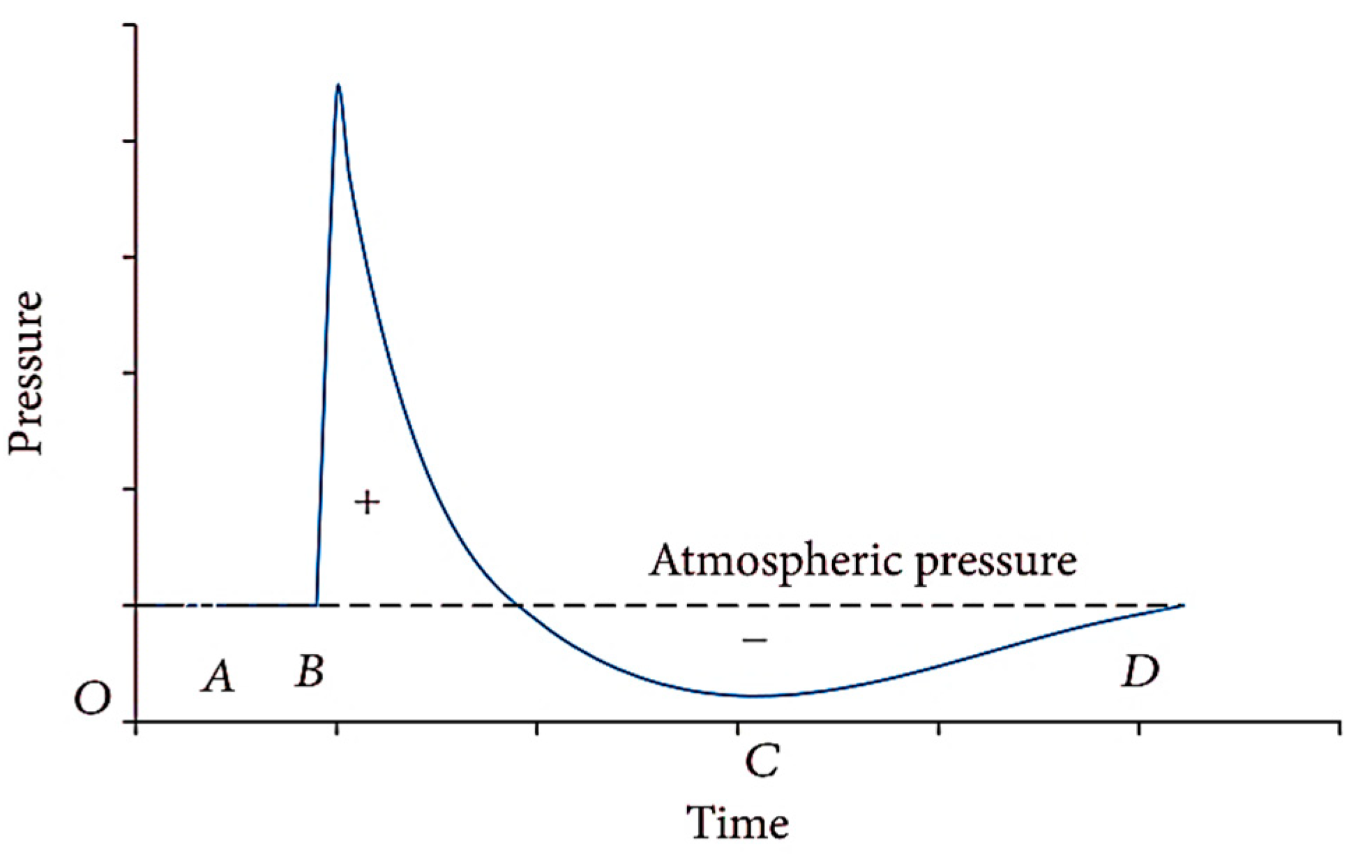
2.1. Blast Loading

When an explosion occurs in the open air, a shock wave containing very dense air is propagated radially outwards from the source center at supersonic speeds [48]. Figure 1 shows the schematic time variations of blast pressure. The time history of the pressure is mainly divided into positive and negative phases. The positive phase begins from the moment the blast wave reaches the structure (point B in Figure 1). At this point, the pressure suddenly reaches its highest value and then gradually decreases to the atmospheric pressure during the positive phase. Then, as it decreases relative to atmospheric pressure, it creates a negative or suction state (point C in Figure 1). The magnitude of the overpressure in the positive phase is much higher than that in the negative phase, and except for lightweight structures, the reverse pressure effects in the negative phase zone are assumed to be negligible [20]. Points A and D in Figure 1 represent the normal atmospheric pressure.
In general, the distance from the source of the explosion (stand-off distance), R, and the explosive charge weight, W, are two crucial factors in determining the specifications of the blast wave. For two different weights of the explosives, if the ratio of the distances from the structure is equal to the ratio of one-third of the power of the charge weight, then the resulting pressure is identical in both cases. This is known as the Hopkinson–Cranz (cube root) scaling law and is expressed according to Equation (1) [49].
R 1 R 2 = ( W 1 W 2 ) 1 / 3 ,
where R is the distance from the center of the explosives, and W is the charge weight for two different cases. The scaled distance (Z) is a basis for evaluating the explosion intensity variations (Equation (2)). Scaled distance is one of the most important characteristics that affects all explosion wave parameters.
Z = R W 1 / 3
In general, there are three types of explosions, based on the measured distance: contact, close-in, and far-field explosions [20]. In the contact state, blast load usually causes a non-uniform pressure distribution on the face of the structure, and the intensified local pressure causes cracks and ruptures. In the close-in state, blast waves are generated in a high impulse area on the face of the structure. A far-filed blast is a state in which the waves reaching the outside of the building are planar due to the great distance from the structure, and the load distribution can be assumed to be linear or uniform. In this study, the close-in explosion scenario was considered for all the models.
Various experimental relations have been presented in different studies to calculate the explosion wave parameters using the parameter Z [20,21,50,51,52,53]. The Conwep module was developed by the US Army Ground Forces Strategic Research Institute following the requirements of TM 5-855-1 Code [54]. The primary purpose of this software is to estimate and apply explosion and impulse loads on the external surface of structures. In this study, the capabilities of this sub-program in ABAQUS were used to calculate the blast load specifications.

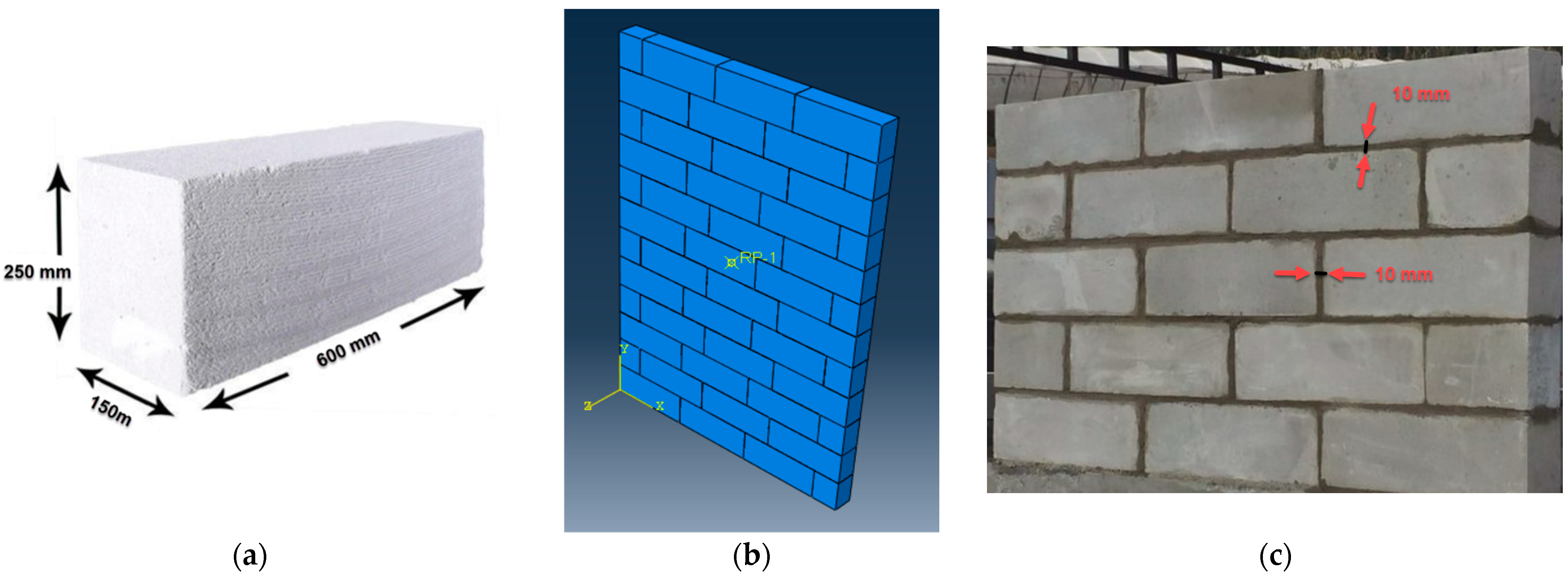
2.2. AAC and Grout Materials

Autoclaved masonry walls are defined in MSJC Code [55] as masonry AAC units placed and connected with suitable mortar or adhesives. These walls may be made with or without reinforcement. Equations (3)–(7) estimate the AAC material specifications [55].
E = 6500 ( f A A C ) 0.6           ( Mpa ) ,
f t   A A C = 0.2 f A A C           ( Mpa ) ,
f v = 0.15 f A A C                 ( Mpa ) ,
E v = 0.4   E ,
E g = 500   f g ´ ,
where f A A C is the compressive strength, E is the modulus of elasticity, f t   A A C is the tensile strength, f v is the direct shear strength, E v is the shear modulus of AAC materials, f g ´ is the compressive strength of adhesive or grout, and E g   is the elastic modulus of adhesive or grout. In this study, the compressive strength of the considered AAC materials and the compressive and tensile strengths of mortar (adhesive) were determined experimentally in the laboratory. Other properties needed for finite element modeling of the materials were estimated using the equations proposed in MSJC. Here, in defining the constitutive behavior of AAC material, the equation proposed by Entezari and Esmaili [56] was used, which is given in Equations (8) and (9).
f c = f c [ n p q ( ε c ε 0 ) ( ε c ε 0 ) n p q + n p q 1 ] ,
q = 1.25 + 0.009 f c ,
For the ascending region, p and q are constants assumed to be 3 and 1, respectively. The quantity of n p q is determined based on the properties of concrete, such as compressive strength, modulus of elasticity, and strain corresponding to the maximum stress. The values of n and p for the descending region are the same as those for the ascending part, and the value of q is determined using the return point of the descending curve. According to the experiments, the stress–strain curve obtained for this study is plotted in Figure 2.
The modulus of elasticity of AAC materials was 1716 MPa, and the Poisson’s ratio was 0.2. To define the nonlinear properties of AAC concrete, the concrete damage plastic (CDP) model was used here, the specifications of which are given in Table 1.

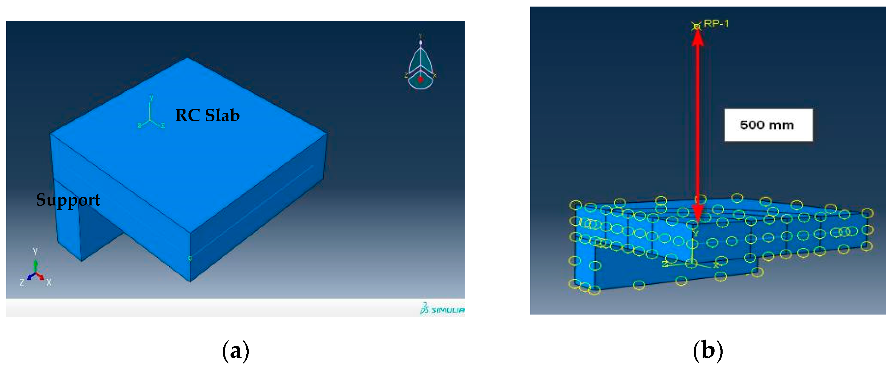
2.3. Numerical Modeling

ABAQUS/Explicit [57] is a finite element package based on an explicit integration approach used to solve extreme nonlinear systems such as high strain rate loadings. In high-velocity dynamic phenomena such as explosive and impulse loads, which apply an intense load in a very short time, it is practically impossible for the FE solution to converge in the implicit approach. Therefore, in this study, the Explicit solver was used to analyze AAC masonry models under explosion loads. ABAQUS includes an extensive library of continuum three-dimensional solid elements which are suitable for modeling solid objects. In this study, C3D20 and C3D8 were used in modeling masonry components made with AAC units. Based on a mesh sensitivity analysis, a solid elements’ meshing size of up to 15 mm was selected.
In ABAQUS, Conwep subroutine can calculate the blast pressure distribution in various structures [57]. In this study, the Conwep feature was used for blast loading. Thus, by entering the explosive charge weight and the stand-off distance, the program automatically calculates the spatial and temporal distribution of the blast pressure on the interaction surface. In this study, the blast event was defined as an air blast in Conwep subroutine, and one side of the wall was considered the blast wave interaction zone.

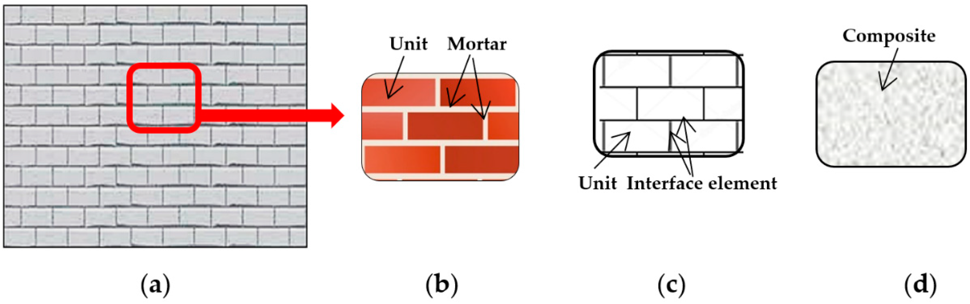
2.4. FE modeling of Masonry Walls

In addition to the analytical approaches [58] and discrete-element analysis [59], numerical methods can be successfully applied to modeling and analysis of masonry walls. Generally, there are three main methods for developing the FE model of infilled frame walls [60,61], including detailed micro modeling, simplified micro modeling, and macro modeling (Figure 3).
Micro modeling can be performed in accurate or simplified manners. The accurate detailed modeling provides the most realistic state or representation of a masonry wall composite. In the accurate approach, the construction units and joints of the mortar layers are modeled, and the properties of each material are assigned separately. The requirements related to the aspect ratio of the elements in meshing, the low thickness, and the long mortar joints mean the accurate detailed micro model needs a very fine mesh. For this reason, most complex calculations require considerable time [43,62,63,64].
In simplified micro modeling, bricks (blocks) and mortar are not modeled separately. The mortar is bonded to homogeneous construction units and added to the unit by a zero-thickness interface element. Mortar joints are added to the intermediate elements representing crack and slip surfaces [32,64]. Using this modeling approach, accuracy is expected to decrease to some extent [65]. In this study, a simplified micro modeling approach was used to prepare masonry wall models with AAC units. Therefore, the mortar was not modeled, and its behavior was considered by adding contact elements between the construction units.
In the macro modeling methodology, the whole infilled wall is modeled as a homogeneous material with equivalent properties regardless of its constituent units. The accuracy of this modeling approach is lower, and the analysis speed is much higher than that of the micro models. It should be noted that the mechanical properties of materials have different values for various conditions, i.e., the arrangement of bricks and horizontal/vertical joints of the mortar in the wall cause the varied stiffness values in different directions [66,67].

2.5. Properties of Interface Elements

The elastic properties of mortar joints are determined by normal stiffness (Knn) and shear stiffness values (Ktt and Kss). If the interaction between the two pieces is similar to that of adhesive, then adhesive elements can be used. In terms of elastic properties, the relationships between stress and vertical and shear strains can be defined as coupled or uncoupled. The stress–strain relationship for uncoupled and coupled states is in the form of Equations (10) and (11), respectively.
{ t n t s t t } = [ K n n 0 0 0 K s s 0 0 0 K t t ] . { ε n ε s ε t } ,
{ t n t s t t } = [ K n n K n s K n t K n s K s s K s t K n t K s t K t t ] . { ε n ε s ε t } ,
where t n ,   t s , and t t are the vertical and shear stresses in two directions, the matrix k is the corresponding stiffness, and ε is the vector of strains for the interface plane. The entries of the main diagonal of the stiffness matrix are the normal and shear stiffness in the main directions of the interface. Here, normal (Kn) and shear (Ks = Kt) stiffness were used to define the adhesive behavior according to Equations (12) and (13).
K n = E u E m h m ( E u E m ) ,
K s = K t = G u G m h m ( G u G m ) ,
where hm, Gm, and Em are the thickness, shear modulus, and modulus of elasticity of the mortar, and Gu and Eu are the shear modulus and modulus of elasticity of the block. The coefficient of friction of the layer was also defined as 0.7.

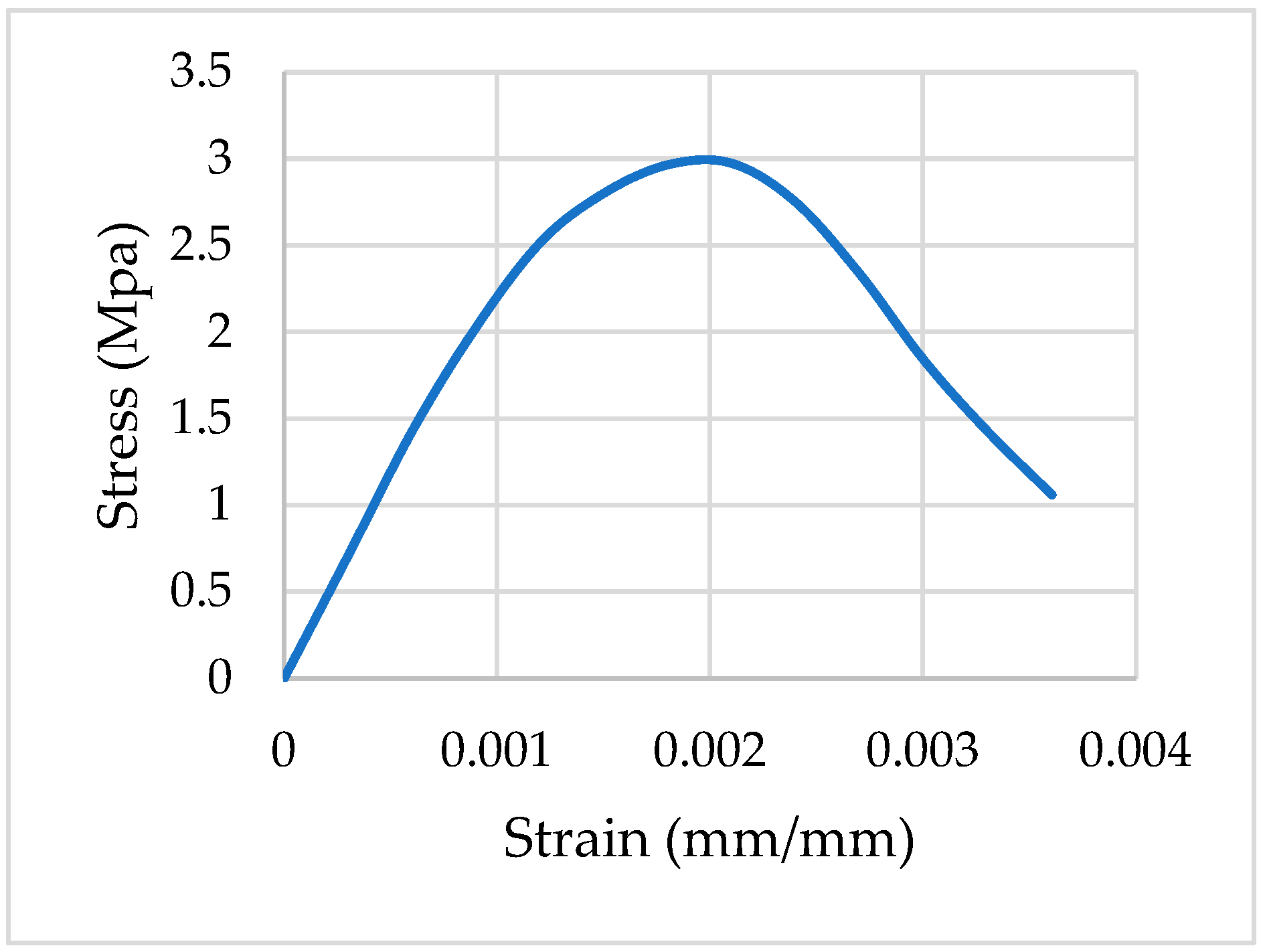
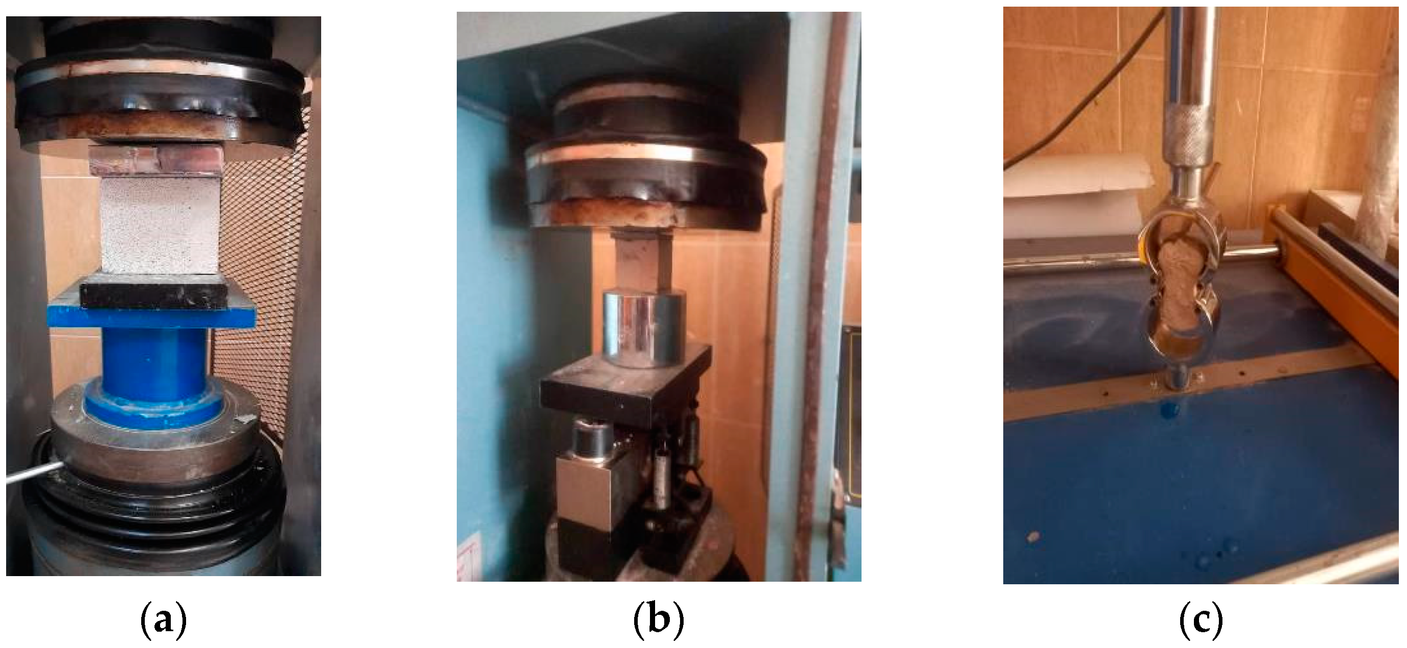
2.6. Mechanical Properties of AAC Materials and Grout

The AAC material mixture considered in this study is summarized in Table 2. With the lack of reliable data related to the mechanical properties of AAC materials, experimental tests were performed on AAC block samples prepared from Aranshahr Aran Polymer Concrete Plant (East Azerbaijan, Iran). The requirements of the ASTM C495 [68] code were used to measure the compressive strength of cubic specimens with the dimensions of 10 cm (Figure 4a). The ASTM C109 [69] code was also used here to determine the compressive strength of adhesive materials (Figure 4b). The dimensions of the cube molds in this experiment were 50 mm, and the samples were treated in water for seven days. The tensile strength of the briquette samples was also determined according to the requirements of the ASTM C 307-3 [70] code (Figure 4c). According to the results, the average compressive strength of the AAC block was about 3 MPa. Moreover, the average compressive strength of the mortar (adhesive) was 10 MPa, and its tensile strength was 1.3 MPa.
In this study, the blast loading was assumed to have occurred as a result of typical suitcase bombs at reasonable distances from the wall face. In addition, the internal pores modeling of the AAC structure was ignored. Experimental data collection and available information from the manufacturer and previous studies were used here to estimate the mechanical properties of AAC material. Moreover, the compressive and tensile strength tests were performed on the standard AAC and the special mortar specimens. The explicit finite element software ABAQUS/Explicit was used for modeling and analysis of masonry walls under explosion loads. Using suitable material models, numerical modeling of the masonry walls made of AAC block units was created and analyzed under various blast loading scenarios perpendicular to the wall face. The cracking, displacement responses, stress distribution, and energy absorption patterns in AAC wall models were investigated and compared.

2.7. Considered Models

In the modeling stage, according to Figure 5, the height and width of the wall were 3 and 2 m, respectively, and the dimensions of AAC blocks were 600 × 250 mm with thicknesses of 15, 20, and 25 cm. The thickness of the mortar layer was also considered to be 10 mm. According to Figure 6, the boundary conditions of the wall were in three different states. The models studied here were subject to the explosions caused by 5 and 7 kg of TNT at the stand-off distances of 2, 5, and 10 m. In all models, the distance of the blast center from the ground (its height from the base of the wall) was considered to be 500 mm. Therefore, in general, 18 models of AAC masonry walls were considered here, with the specifications summarized in Table 3. It should be noted that no axial loading on the walls was taken into account since the considered walls were not assumed to be load-bearing structural components.

3. Results and Discussion

3.1. Validation

Kumar et al. [71] conducted a study on the behavior of RC slabs against blast loading. The slab with dimensions of 1000 × 1000 × 100 mm was exposed to explosions with a scaled distance of 0.079–0.527 m/kg1/3. Here, to validate the process of blast load calculations in ABAQUS, this concrete slab was modeled, and the blast pressure distribution was compared to the original reference. The slab-32 model in reference [71] was modeled under the effect of a blast of 2 kg TNT at a distance of 0.5 m (Z = 0.3968 m/kg1/3). Here, due to the symmetry of the structure and loading, only one-fourth of the concrete slab was modeled and analyzed. The considered RC plate was a square with 500 mm length of side and 100 mm thickness. The finite element model of the RC slab with its support structure prepared here and the definition of the explosive charge are given in Figure 7.
Figure 8 shows the time history of the calculated pressure in the middle of the slab in this study compared to the reference [71]. It can be observed that the maximum overpressure difference is equal to 100 % - 42 . 36 44 . 0 × 100 % = 3 . 72 % , which is in an acceptable range.

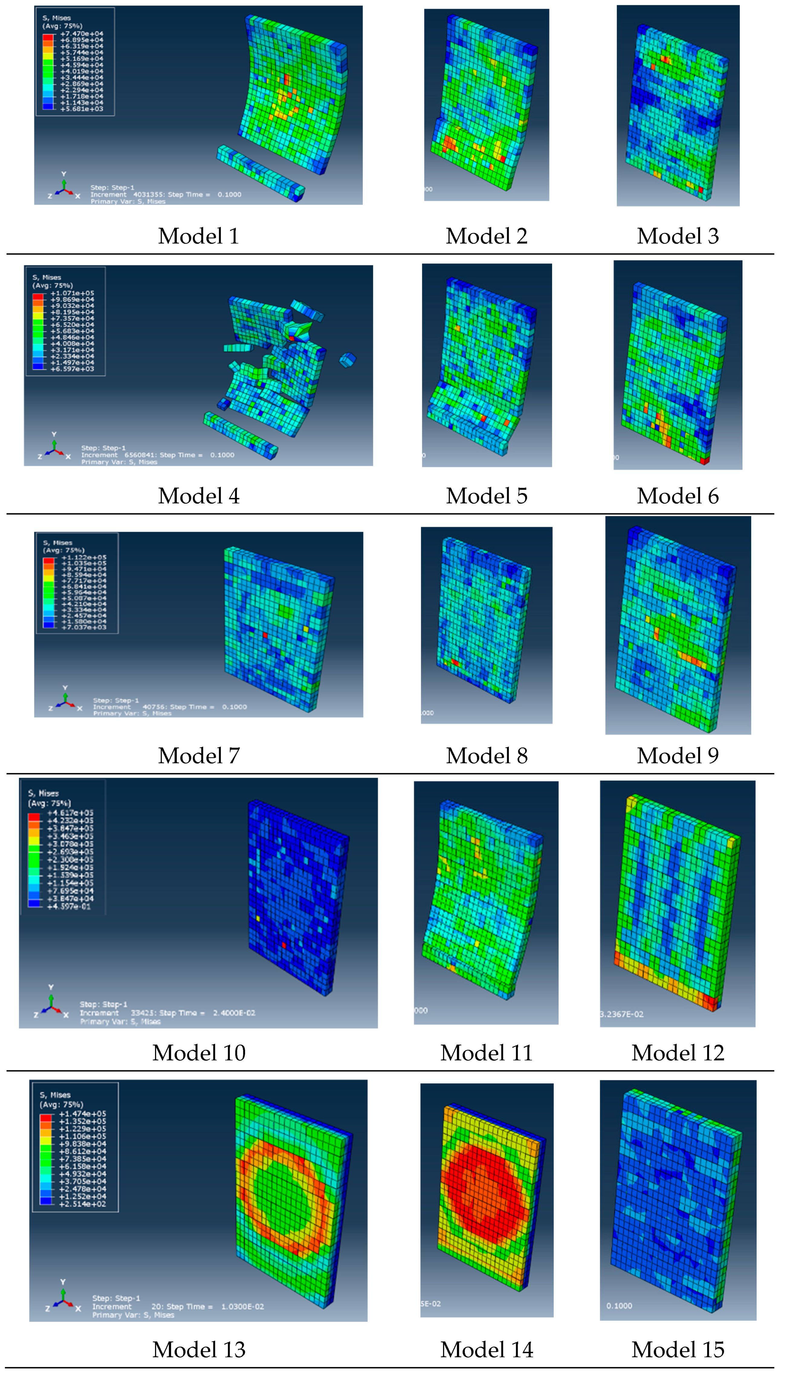
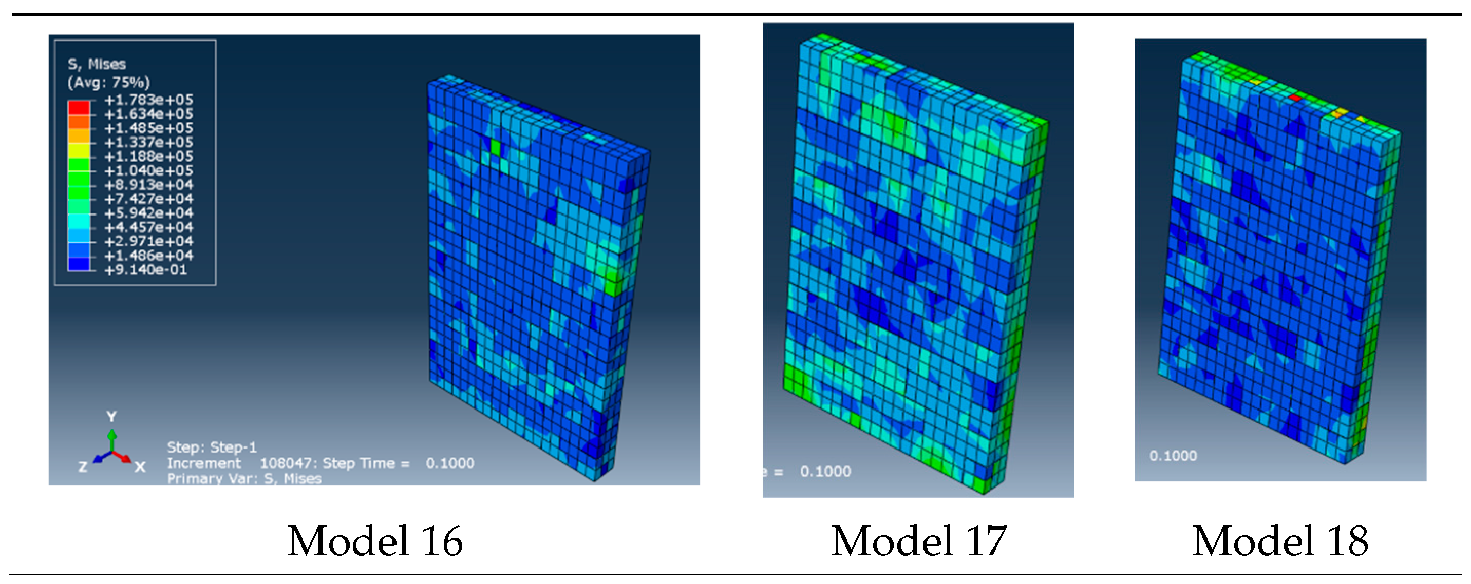
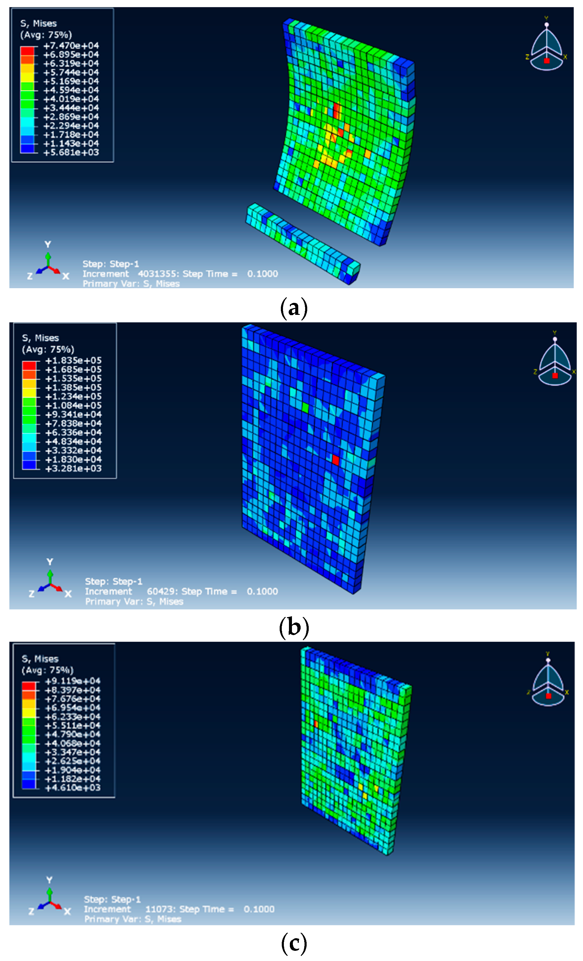
3.2. Von Mises Stress Distribution

After verifying the modeling procedure, the wall models were simulated, and structural responses were monitored and investigated. Figure 9 shows the maximum von Mises stress distribution in the studied wall models under blast loading. Table 4 also shows the maximum stresses in each model. It can be observed that with a reduction in the stand-off distance, the stress level was increased and distributed over a wider area of the wall. For example, in model-1 with a stand-off distance of 2 m, the maximum stress was 118.56 kN/m2 higher than that in model-2 with a stand-off distance of 5 m. As the amount of TNT increased, the stress also increased, and more significant damages were observed in the models. For example, in model-3, with an explosive charge weight of 5 kg, the maximum stress was 29.32 kN/m2 lower than that in model-6, with an explosive charge weight of 7 kg. In addition, as the thickness of the walls increased, the stress generally decreased. For example, in model-13 with a thickness of 25 cm, the maximum stress was 73.55 kN/m2 lower compared to model-7 with the wall thickness of 20 cm.
Since the considered boundary conditions in these models were fixed at both ends (Figure 6a), the one-way behavior of the wall is obvious in Figure 9. According to Figure 9, shear failure was the dominant failure mode, since the grout shear strength was less than its compressive strength.

3.3. Displacement Responses

According to Figure 10, the displacement time history at the center of the wall was obtained for different thicknesses. It can be seen that the closer the explosives to the wall, the greater the displacement. With an explosive charge weight of 7 kg, for all wall thicknesses, the displacement was more significant than that for the other charge weights. For example, Models 4 and 6 had higher displacements than Models 1 and 3, respectively. According to the results, it can be observed that at a stand-off distance of 2 m (such as in Model-1), the wall models practically failed and had a larger displacement compared to the other models. Therefore, it can be concluded that at short stand-off distances, AAC-based masonry walls do not have enough resistance against blast loading, and a retrofitting scheme is required.

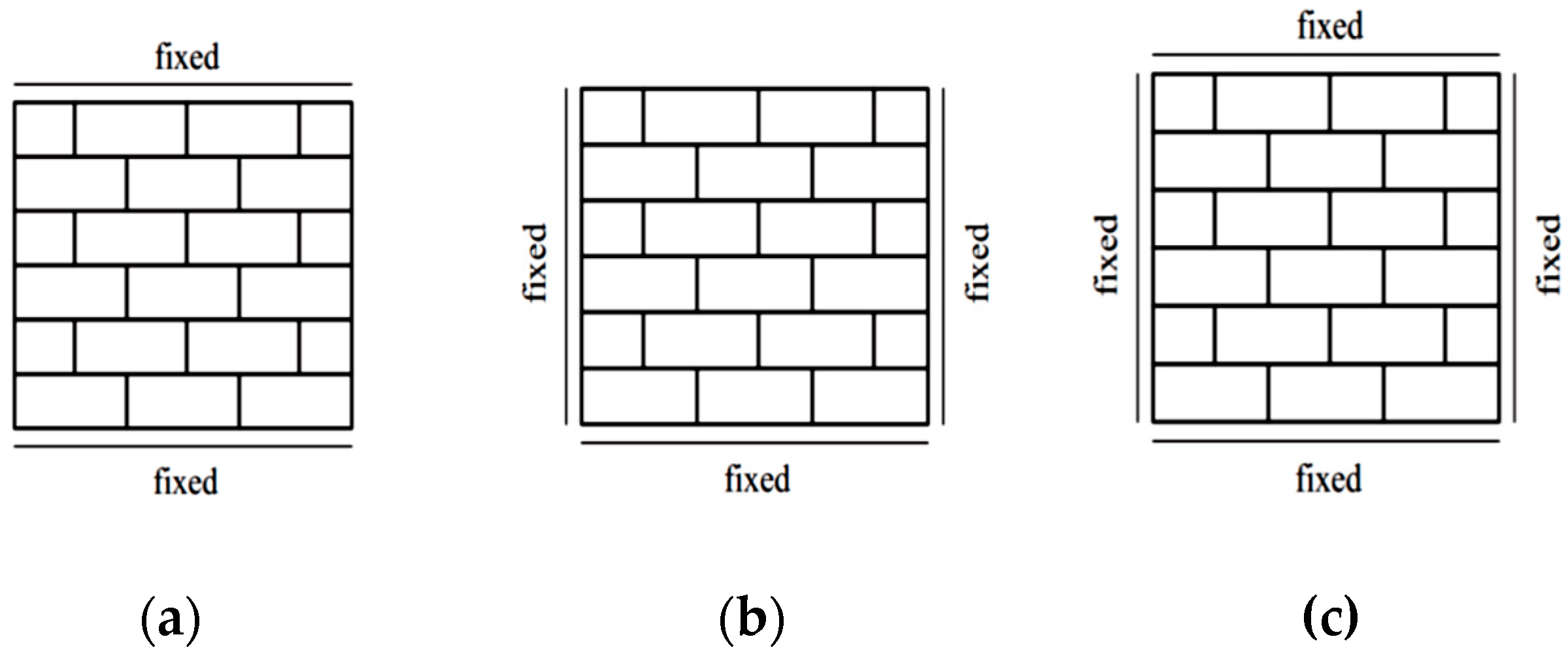
3.4. The Influence of the Boundary Conditions

There were three different cases for the support conditions of the walls. In the first case, the base of the wall was assumed to be restrained. In the second case, the whole perimeter of the wall was restrained, and in the third case, the three sides of the wall (bottom and sides) were restrained. Figure 11 shows the maximum stress distribution for different support conditions in the wall models. Clearly, the greater the restraints of the sides of the wall (case b), i.e., the better the restraining of the wall to the structural components of the building, the lower the stress in the wall. As such, in case “a” with the base of the wall constrained, a large surface of the wall had stress ranging from 2.3 × 10⁴ to 5.2 × 10⁴  kgf m 2 . In case “c” with the base of the wall and the sides restrained, a large surface of the wall had the stress of 1.2 × 10⁴ to 4.8 × 10⁴ kgf m 2 . Finally, in case “b” with the whole sides of the wall restrained, a large surface of the wall had the stress of 3.2 × 10³ to 3.3 × 10⁴  kgf m 2 .
According to Figure 11a, shear failure was obvious in the wall with one-way behavior. Two-way performance of the wall, as in Figure 11b, led to a decrease in the deformations compared to the other BCs. However, it increased the induced stress to the elements. As was anticipated, the boundary conditions had significant effects on the response of the walls made with AAC, similar to other masonry walls [22,23,24].

3.5. Base Shear Force

Figure 12 indicates the temporal variations of the base shear in wall models with different thicknesses. It can be seen that with an increase in wall thickness, the force incurred on the base of the wall due to blast loading was significantly reduced. Therefore, the thickness of the walls was very effective in reducing the explosive demand on the AAC-based masonry walls. For example, for a wall with a thickness of 15 cm, the values of the base shear were about ten times higher compared those for a wall with a thickness of 25 cm.

4. Conclusions

Autoclaved aerated concrete (AAC) block is used in the construction of load-bearing and masonry walls due to its low thermal expansion coefficient, high fire resistance, and low weight. However, the low strength of materials and the heterogeneity of the material lead to the vulnerability of AAC masonry walls under external loads. To reduce the potential hazards in the structure and enhance the safety level, it is necessary to investigate the dynamic responses and failure of AAC masonry walls under explosive loads. This study aimed to investigate the behavior of AAC walls under blast loading. Therefore, the specifications of the materials required for modeling were first determined through experimental tests. Then, by modeling and analysis of the AAC walls in ABAQUS/Explicit, the behavior of these walls was investigated under blast loads. The main outcomes are as follows:
  • Considering the weight of TNT used in a short distance (R = 2 m), it was observed that very large local stresses were created in the wall, which caused the wall to collapse in a very short time. It should be noted that at distances of less than 2 m, the wall models diverged at the very first moments. Therefore, the analysis and presentation of their results were avoided here.
  • With the increasing charge weight, wall performance degraded. The stress level in the case of an explosive charge weight of 7 kg TNT increased by about 10% compared to that for 5 kg TNT. It is important to note that the walls modeled in this study under a charge larger than 7 kg TNT had a rapid failure in the initial moments. Therefore, considering the typical values of charge weight in the explosion events of hand grenades and suitcase bombs (about 20 kg-TNT) [72], it can be stated that masonry walls made with AAC do not have a good explosion resistance and would need retrofitting.
  • Some retrofitting methods in masonry walls could involve using CFRP coating, steel wire mesh, and laminating. In addition, polyurea and polyurethane coatings, using steel sheets, aluminum foam, and engineered cementitious composites, are suggested for masonry units that can be applied to walls made with AAC.
  • With the increasing charge weight and decreasing stand-off distance, the wall displacement increased significantly, so that at a distance of 2 m, the displacement was several times that for the 5- and 10-m distances. In the walls with thicknesses of 15, 20, and 25 cm, the performance was also observed to be the same. As the amount of TNT increased, the stress values increased, and more damage was observed in the walls.
  • The thickness of the walls was very effective in reducing the explosive demand force. For example, for a wall with a thickness of 15 cm, compared to that with a thickness of 25 cm, the base shear values induced by the same explosion were about 10 times higher.
To complete this study and achieve practical findings, complementary studies will be executed on construction units made of AAC blocks, including AAC walls reinforced by various methods such as using horizontal and vertical rebar meshes. The effect of various characteristics of mortar and adhesive on the behavior of AAC walls under blast loads will also be investigated.
It should be noted that the modeling of the walls built with AAC blocks in ABAQUS finite element software requires more extensive data and more detailed experiments. In particular, dynamic properties under high strain rates require further experimental and laboratory studies.

Author Contributions

Conceptualization, S.M. and E.N.F.; methodology, S.M. and D.J.; software, R.B.G.; validation, R.B.G.; formal analysis, S.M. and R.B.G.; writing—original draft preparation, S.M.; writing—review and editing, E.N.F.; project administration, D.J. All authors have read and agreed to the published version of the manuscript.

Funding

This research received no external funding.

Institutional Review Board Statement

Not applicable.

Informed Consent Statement

Not applicable.

Data Availability Statement

All the data used to support the findings of the study are included within the article.

Conflicts of Interest

The authors declare no conflict of interest.

References

  1. Korniyenko, S.V.; Vatin, N.I.; Gorshkov, A.S. Heat and power characteristics analysis carried out for the residential building made of autoclaved aerated concrete blocks. Constr. Unique Build. Struct. 2016, 12, 45–60. [Google Scholar] [CrossRef]
  2. Winkels, B.; Nebel, H.; Raupach, M. Carbonation of autoclaved aerated concrete containing fly ash. ce/papers 2018, 2, 47–51. [Google Scholar] [CrossRef]
  3. Gyurkó, Z.; Jankus, B.; Fenyvesi, O.; Nemes, R. Sustainable applications for utilization the construction waste of aerated concrete. J. Clean. Prod. 2019, 230, 430–444. [Google Scholar] [CrossRef]
  4. Saghi, H.; Arefizadeh, N. Quantitative and Qualitatively Evaluation of New Technologies in Perspective of Construction Optimization. Am. J. Civ. Eng. 2015, 3, 64–68. [Google Scholar] [CrossRef]
  5. Hammond, G.P.; Jones, C.I. Embodied energy and carbon in construction materials. Proc. Inst. Civ. Eng. Energy 2008, 161, 87–98. [Google Scholar] [CrossRef]
  6. Sherin, K.; Saurabh, J.K. Review of autoclaved aerated concrete: Advantages and disadvantages. In Proceedings of the National Conference of Advanced Structures, Materials and Methodology in Civil Engineering-ASMMCE-2018, Punjab, India, 3–4 November 2018. [Google Scholar]
  7. Momeni, M.; Hadianfard, M.A.; Bedon, C.; Baghlani, A. Damage evaluation of H-section steel columns under impulsive blast loads via gene expression programming. Eng. Struct. 2020, 219, 110909. [Google Scholar] [CrossRef]
  8. Momeni, M.; Hadianfard, M.A.; Bedon, C.; Baghlani, A. Numerical damage evaluation assessment of blast loaded steel columns with similar section properties. Structures 2019, 20, 189–203. [Google Scholar] [CrossRef]
  9. Esameelnia Omran, M.; Mollaei, S. Investigation of Axial Strengthened Reinforced Concrete Columns under Lateral Blast Loading. Shock Vib. 2017, 2017, 94–113. [Google Scholar] [CrossRef]
  10. Mollaei, S.; Babaei, M.; JalilKhani, M. Assessment of Damage and Residual Load Capacity of the Normal and Retrofitted RC Columns against the Impact Loading. J. Rehab. Civ. Eng. 2021, 9, 29–51. [Google Scholar] [CrossRef]
  11. Deyazada, M.; Vandoren, B.; Dragan, D.; Degée, H. Experimental investigations on the resistance of masonry walls with AAC thermal break layer. Constr. Build. Mater. 2019, 224, 474–492. [Google Scholar] [CrossRef]
  12. Yankelevsky, D.Z.; Avnon, I. Autoclaved aerated concrete behavior under explosive action. Constr. Build. Mater. 1998, 12, 359–364. [Google Scholar] [CrossRef]
  13. Tanner, J.E.; Varela, J.L.; Klingner, R.E.; Brightman, M.J.; Cancino, U. Seismic testing of autoclaved aerated concrete shear walls: A comprehensive review. ACI Struct. J. 2005, 102, 374. [Google Scholar]
  14. Tanner, J.E.; Varela, J.L.; Klingner, R.E. Design and seismic testing of two-story, full-scale autoclaved aerated concrete assemblage specimen. ACI Struct. J. 2005, 102, 114. [Google Scholar]
  15. ACI Committee 523. Guide for Design and Construction with Autoclaved Aerated Concrete Panels (ACI 523.4R-09); American Concrete Institute: Farmington Hills, MI, USA, 2009. [Google Scholar]
  16. Uddin, N.; Shelar, K.V.; Fouad, F. Impact response of autoclave aerated concrete/FRP sandwich structures. In Proceedings of the Structures Congress 2006: Structural Engineering and Public Safety, ASCE, St. Louis, MO, USA, 18–21 May 2006. [Google Scholar] [CrossRef]
  17. Tomaževič, M.; Gams, M. Shaking table study and modelling of seismic behaviour of confined AAC masonry buildings. Bull. Earthq. Eng. 2012, 10, 863–893. [Google Scholar] [CrossRef]
  18. Bayat, A.; Liaghat, G.H.; Ghalami-Choobar, M.; Ashkezari, G.D.; Sabouri, H. Analytical modeling of the high-velocity impact of autoclaved aerated concrete (AAC) blocks and some experimental results. Int. J. Mech. Sci. 2019, 159, 315–324. [Google Scholar] [CrossRef]
  19. U.S. Department of the Army, the Navy and Air Force. Fundamental of Protective Design for Conventional Weapons-Technical Manual (TM 5-855-1); U.S. Department of the Army: Washington, DC, USA, 1986. [Google Scholar]
  20. U.S. Department of the Army, the Navy and Air Force. The Design of Structures to Resist the Effects of Accidental Explosions-Technical Manual (TM 5-1300); U.S. Department of the Army: Washington, DC, USA, 1990. [Google Scholar]
  21. U.S. Department of Defense (DOD). Structures to Resist the Effects of Accidental Explosions (UFC 3-340-02); DOD: Washington, DC, USA, 2008. [Google Scholar]
  22. Hao, H.; Wu, C. Numerical simulation of damage of low-rise RC frame structures with infilled masonry walls to explosive loads. Aust. J. Struct. Eng. 2006, 7, 13–22. [Google Scholar] [CrossRef]
  23. Wu, C.; Hao, H. Safe scaled distance for masonry infilled RC frame structures subjected to airblast loads. J. Perform. Constr. Facil. 2007, 21, 422–431. [Google Scholar] [CrossRef]
  24. Wei, X.; Stewart, M.G. Model validation and parametric study on the blast response of unreinforced brick masonry walls. Int. J. Impact Eng. 2010, 37, 1150–1159. [Google Scholar] [CrossRef]
  25. Ahmad, S.; Elahi, A.; Pervaiz, H.; Rahman, A.G.A.; Barbhuiya, S. Experimental study of masonry wall exposed to blast loading. Mater. Constr. 2014, 64, e007. [Google Scholar] [CrossRef]
  26. Pandey, A.; Bisht, R. Numerical modelling of infilled clay brick masonry under blast loading. Adv. Struct. Eng. 2014, 17, 591–606. [Google Scholar] [CrossRef]
  27. Pereira, J.M.; Campos, J.; Lourenço, P.B. Experimental study on masonry infill walls under blast loading. In Proceedings of the 9th International Masonry Conference, Guimarães, Portugal, 7–9 July 2014. [Google Scholar]
  28. Shi, Y.; Xiong, W.; Li, Z.X.; Xu, Q. Experimental studies on the local damage and fragments of unreinforced masonry walls under close-in explosions. Int. J. Impact Eng. 2016, 90, 122–131. [Google Scholar] [CrossRef]
  29. Parisi, F.; Balestrieri, C.; Asprone, D. Blast resistance of tuff stone masonry walls. Eng. Struct. 2016, 113, 233–244. [Google Scholar] [CrossRef]
  30. Keys, R.A.; Clubley, S.K. Experimental analysis of debris distribution of masonry panels subjected to long duration blast loading. Eng. Struct. 2017, 130, 229–241. [Google Scholar] [CrossRef]
  31. Badshah, E.; Naseer, A.; Ashraf, M.; Ahmad, T. Response of masonry systems against blast loading. Def. Technol. 2021, 17, 1326–1337. [Google Scholar] [CrossRef]
  32. Zeng, B.; Li, Y.; Noguez, C.C. Modeling and parameter importance investigation for simulating in-plane and out-of-plane behaviors of un-reinforced masonry walls. Eng. Struct. 2021, 248, 113233. [Google Scholar] [CrossRef]
  33. ASCE/SEI 59-11; Blast Protection of Buildings. American Society of Civil Engineers: Reston, VA, USA, 2011.
  34. Stanley, M.; Metzger, J.; Martinez, R.; Koenig, J. UL-Like Testing of Commercial Off-the-Shelf Products That Enhance the Blast and Ballistic Resistance of Structures, Quick Look Report 2; New Mexico Tech, Energetic Materials Research and Testing Center, Karagozian & Case: Burbank, CA, USA, 2005. [Google Scholar]
  35. Tan, K.H.; Patoary, M.K.H. Blast resistance of FRP-strengthened masonry walls. I: Approximate analysis and field explosion tests. J. Compos. Constr. 2009, 13, 422–430. [Google Scholar] [CrossRef]
  36. Baylot, J.T.; Bullock, B.; Slawson, T.R.; Woodson, S.C. Blast response of lightly attached concrete masonry unit walls. J. Struct. Eng. 2005, 131, 1186–1193. [Google Scholar] [CrossRef]
  37. Alsayed, S.H.; Elsanadedy, H.M.; Al-Zaheri, Z.M.; Al-Salloum, Y.A.; Abbas, H. Blast response of GFRP-strengthened infill masonry walls. Constr. Build. Mater. 2016, 115, 438–451. [Google Scholar] [CrossRef]
  38. Bui, T.T.; Limam, A. Out-of-plane behaviour of hollow concrete block masonry walls unstrengthened and strengthened with CFRP composite. Compos. Part B Eng. 2014, 67, 527–542. [Google Scholar] [CrossRef]
  39. Chen, L.; Fang, Q.; Fan, J.; Zhang, Y.; Hao, H.; Liu, J. Responses of masonry infill walls retrofitted with CFRP, steel wire mesh and laminated bars to blast loadings. Adv. Struct. Eng. 2014, 17, 817–836. [Google Scholar] [CrossRef]
  40. Ghaderi, M.; Maleki, V.A.; Andalibi, K. Retrofitting of unreinforced masonry walls under blast loading by FRP and spray on polyurea. Cumhur. Üniversitesi Fen Fakültesi Fen Bilimleri Derg. 2015, 36, 462–477. [Google Scholar] [CrossRef]
  41. Urgessa, G.S.; Maji, A.K. Dynamic response of retrofitted masonry walls for blast loading. J. Eng. Mech. 2010, 136, 858–864. [Google Scholar] [CrossRef]
  42. Xu, W.X.; Bao, Q.; Li, Z.; Fan, J.Y. Numerical Analysis on the Behavior of Autoclaved Aerated Concrete Block Infilled Wall Subjected to Gas Explosion. Appl. Mech. Mater. 2015, 723, 259–265. [Google Scholar] [CrossRef]
  43. Li, Z.; Chen, L.; Fang, Q.; Hao, H.; Zhang, Y.; Chen, W.; Xiang, H.; Bao, Q. Study of autoclaved aerated concrete masonry walls under vented gas explosions. Eng. Struct. 2017, 141, 444–460. [Google Scholar] [CrossRef]
  44. Wang, J.; Ren, H.; Wu, X.; Cai, C. Blast response of polymer-retrofitted masonry unit walls. Compos. Part B Eng. 2017, 128, 174–181. [Google Scholar] [CrossRef]
  45. Liu, C.; Hou, J.; Hao, Y.; Hao, H.; Meng, X. Effect of high strain rate and confinement on the compressive properties of autoclaved aerated concrete. Int. J. Impact Eng. 2021, 156, 103943. [Google Scholar] [CrossRef]
  46. Sovják, R.; Koutný, O.; Hála, P. Penetration Resistance of Building Materials against 7.62-mm Armor-Piercing Projectile. J. Mater. Civ. Eng. 2021, 33, 04021224. [Google Scholar] [CrossRef]
  47. Stepinac, M.; Kisicek, T.; Renić, T.; Hafner, I.; Bedon, C. Methods for the Assessment of Critical Properties in Existing Masonry Structures under Seismic Loads—The ARES Project. Appl. Sci. 2020, 10, 1576. [Google Scholar] [CrossRef]
  48. Hinman, E. Primer for Design of Commercial Buildings to Mitigate Terrorist Attacks; Federal Emergency Management Agency (FEMA): Washington, DC, USA, 2003. [Google Scholar]
  49. Cormie, D.; Mays, G.; Smith, P.D. Blast Effects on Buildings, 2nd ed.; Thomas Telford: London, UK, 2009. [Google Scholar]
  50. Brode, H.L. Numerical Solutions of Spherical Blast Waves. J. Appl. Phys. 1955, 26, 766–775. [Google Scholar] [CrossRef]
  51. Newmark, N.M.; Hansen, R.J. Design of blast resistant structures. Shock. Vib. Handb. 1961, 3, 04014007. [Google Scholar]
  52. Mills, C.A. The design of concrete structure to resist explosions and weapon effects. In Proceedings of the 1st International Conference on Concrete for Hazard Protections, Edinburgh, UK, 27–30 September 1987; 1987. [Google Scholar]
  53. Baker, W.E.; Cox, P.A.; Westine, P.S.; Kulesz, J.J.; Strehlow, R.A. Explosion Hazards and Evaluation; Elsevier Scientific: New York, NY, USA, 1983. [Google Scholar]
  54. Hyde, D. User’s Guide for Microcomputer Programs CONWEP and FUNPRO, Applications of TM 5-855-1: Fundamentals of Protective Design for Conventional Weapons; USA Army Engineers Waterways Experimentation: Vicksburg, MS, USA, 1988. [Google Scholar]
  55. Masonry Standards Joint Committee. Building Code Requirements and Specification for Masonry Structures: Containing Building Code Requirements for Masonry Structures (TMS 402-11/ACI 530-11/ASCE 5-11), and Specification for Masonry Structures TMS 402-11/ACI 530-11/ASCE 6-11), and Companion Commentaries; ASCE: Reston, VA, USA, 2016. [Google Scholar]
  56. Entezari, A.; Esmaili, J. Investigation on the Stress Distribution and Flexural Strength of Structural Lightweight Aggregate Concrete. Concr. Res. 2010, 3, 61–72. [Google Scholar]
  57. Abaqus v. 6.14 Documentation; Dassault Systemes Simulia Corporation: Providence, RI, USA, 2011.
  58. Sassu, M.; Andreini, M.; Casapulla, C.; De Falco, A. Archaeological consolidation of UNESCO masonry structures in Oman: The Sumhuram Citadel of Khor Rori and the Al Balid Fortress. Int. J. Archit. Herit. 2013, 7, 339–374. [Google Scholar] [CrossRef]
  59. Pantò, B.; Casapulla, C.; Caliò, I. Discrete rotating links model for the non-linear torsion−shear behaviour of masonry joints. Proc. Inst. Civ. Eng. Eng. Comput. Mech. 2021, 174, 215–235. [Google Scholar] [CrossRef]
  60. Zucchini, A.; Lourenço, P.B. A micro-mechanical model for the homogenisation of masonry. Int. J. Solids Struct. 2002, 39, 3233–3255. [Google Scholar] [CrossRef]
  61. Casapulla, C.; Giresini, L.; Argiento, L.U.; Maione, A. Nonlinear static and dynamic analysis of rocking masonry corners using rigid macro-block modeling. Int. J. Struct. Stab. Dyn. 2019, 19, 1950137. [Google Scholar] [CrossRef]
  62. Maheri, M.R.; Najafgholipour, M.A.; Rajabi, A.R. The influence of mortar head joints on the in-plane and out-of-plane seismic strength of brick masonry walls. Iran. J. Sci. Technol. Trans. Civ. Eng. 2011, 35, 63–79. [Google Scholar]
  63. Gabor, A.; Bennani, A.; Jacquelin, E.; Lebon, F. Modelling approaches of the in-plane shear behaviour of unreinforced and FRP strengthened masonry panels. Compos. Struct. 2006, 74, 277–288. [Google Scholar] [CrossRef]
  64. Lourenço, P.B.; Rots, J. Analysis of Masonry Structures with Interface Elements-Report No. 03-21-22-0; Delft University of Technology: Delft, The Netherlands, 1994. [Google Scholar]
  65. Lourenço, P.B. Computations on historic masonry structures. Prog. Struct. Eng. Mater. 2002, 4, 301–319. [Google Scholar] [CrossRef]
  66. Vecchio, F.J.; Collins, M.P. The modified compression-field theory for reinforced concrete elements subjected to shear. ACI J. 1986, 83, 219–231. [Google Scholar]
  67. Korany, Y.; EL-Haggar, S. Mechanics and modeling of URM structures. In Proceedings of the International Short Course on Architectural and Structural Design of Masonry, Dresden, Germany, 7–18 December 2003. [Google Scholar]
  68. ASTM C495; Standard Test Method for Compressive Strength of Lightweight Insulating Concrete. American Society for Testing and Materials (ASTM): Philadelphia, PA, USA, 2002.
  69. ASTM, C109; Compressive Strength of Hydraulic Cement Mortars (Using 2-in. or 50-mm Cube Specimens). ASTM International: West Conshohocken, PA, USA, 1999; Volume 4.
  70. ASTM C307-03; Standard Test Method for Tensile Strength of Chemical-Resistant Mortar, Grouts and Monolithic Surfacing. ASTM International: West Conshohocken, PA, USA, 2012.
  71. Kumar, V.; Kartik, K.V.; Iqbal, M.A. Experimental and numerical investigation of reinforced concrete slabs under blast loading. Eng. Struct. 2020, 206, 110125. [Google Scholar] [CrossRef]
  72. National Research Council. ISC Security Design Criteria for New Federal Office Buildings and Major Modernization Projects: A Review and Commentary; The National Academies Press: Washington, DC, USA, 2003. [Google Scholar] [CrossRef]
Figure 1. Pressure time history for free explosion [9].
Applsci 12 08725 g001
Figure 2. Stress–strain curve of AAC materials with a compressive strength of 3 MPa.
Applsci 12 08725 g002
Figure 3. Masonry wall modeling approaches: (a) a real masonry wall; (b) accurate detailed micro modeling; (c) simplified micro modeling; (d) macro modeling.
Applsci 12 08725 g003
Figure 4. Test setup for (a) compressive strength of AAC materials; (b) compressive strength of adhesive materials; (c) tensile strength of adhesive materials.
Applsci 12 08725 g004
Figure 5. Specifications of the AAC wall and block model: (a) AAC block dimensions; (b) FE model of the wall; (c) assumed thickness of grout layer.
Applsci 12 08725 g005
Figure 6. Boundary conditions of the walls: (a) fixed top and bottom of the wall; (b) fixed sides and bottom of the wall; (c) fully fixed BCs.
Applsci 12 08725 g006
Figure 7. FE modeling of the slab: (a) modeling in Abaqus for validation; (b) blast loading in Conwep.
Applsci 12 08725 g007
Figure 8. Pressure–time diagram obtained in the present study for validation process.
Applsci 12 08725 g008
Figure 9. The von Mises stress distribution in some of the simulated wall models.
Applsci 12 08725 g009aApplsci 12 08725 g009b
Figure 10. Time–displacement diagrams for wall thicknesses of 15, 20, and 25 cm.
Applsci 12 08725 g010
Figure 11. Distribution of stress in different support conditions: (a) restrained base; (b) restrained whole sides; (c) three-sided restrained.
Applsci 12 08725 g011
Figure 12. Base shear of the wall with thicknesses of 15, 20, and 25 cm.
Applsci 12 08725 g012
Table 1. Parameters of concrete damage plastic (CDP) model used here.
ParameterDilation AngleEccentricityBiaxial-to-Uniaxial Compressive Strength RatioShape Factor FunctionViscoelastic Parameter
Quantity200.11.160.660.001
Table 2. AAC mix design with a density of 500 kg/m3.
MaterialsAmounts (kg/m3)
silica sand350
lime100
cement25
aluminum powder0.5
water330
Table 3. Details of the studied models.
ModelThickness (cm)Stand-Off Distance (m)Charge Weight (kg) Scaled Distance (m/kg1/3)
Model-115251.170
Model-215552.924
Model-3151055.848
Model-415271.046
Model-515572.614
Model-6151075.228
Model-720251.170
Model-820552.924
Model-9201055.848
Model-1020271.046
Model-1120572.614
Model-12201075.228
Model-1325251.170
Model-1425552.924
Model-15251055.848
Model-1625271.046
Model-1725572.614
Model-18251075.228
Table 4. Maximum stress values in the models.
ModelThickness (cm)Stand-Off Distance (m)Charge Weight (kg) Maximum Stress (kgf/m2)
Model-115257.470 × 104
Model-215556.261 × 104
Model-3151055.494 × 104
Model-415271.071 × 105
Model-515579.522 × 104
Model-6151075.793 × 104
Model-720251.122 × 105
Model-820556.234 × 104
Model-9201059.829 × 104
Model-1020274.617 × 105
Model-1120576.715 × 104
Model-12201071.367 × 104
Model-1325251.474 × 105
Model-1425553.933 × 104
Model-15251056.075 × 104
Model-1625271.783 × 105
Model-1725575.638 × 104
Model-18251076.591 × 104
Publisher’s Note: MDPI stays neutral with regard to jurisdictional claims in published maps and institutional affiliations.

