Vibration Reduction of a Timoshenko Beam with Multiple Parallel Nonlinear Energy Sinks


Abstract
:1. Introduction
2. Methods
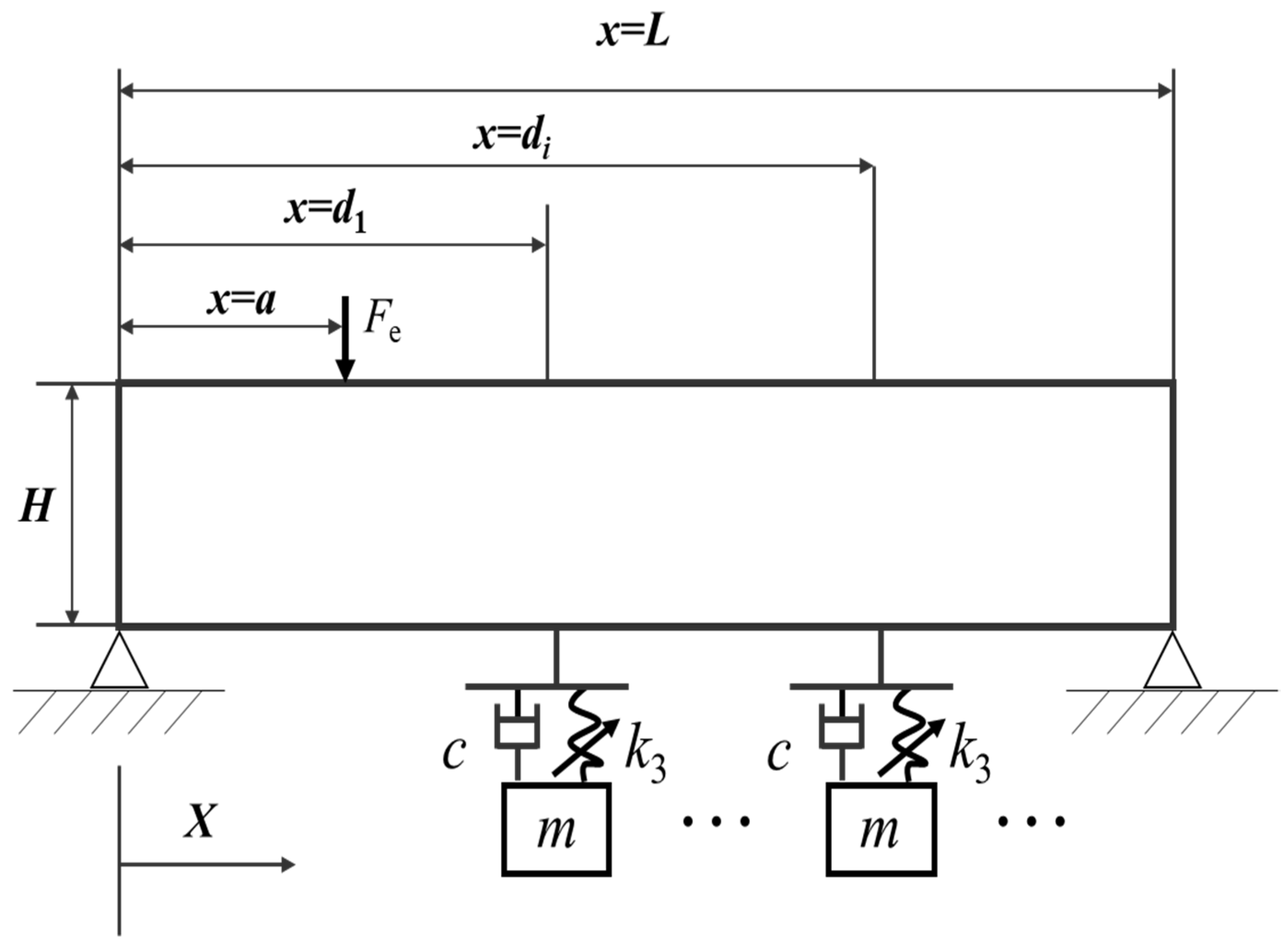
2.1. Modeling
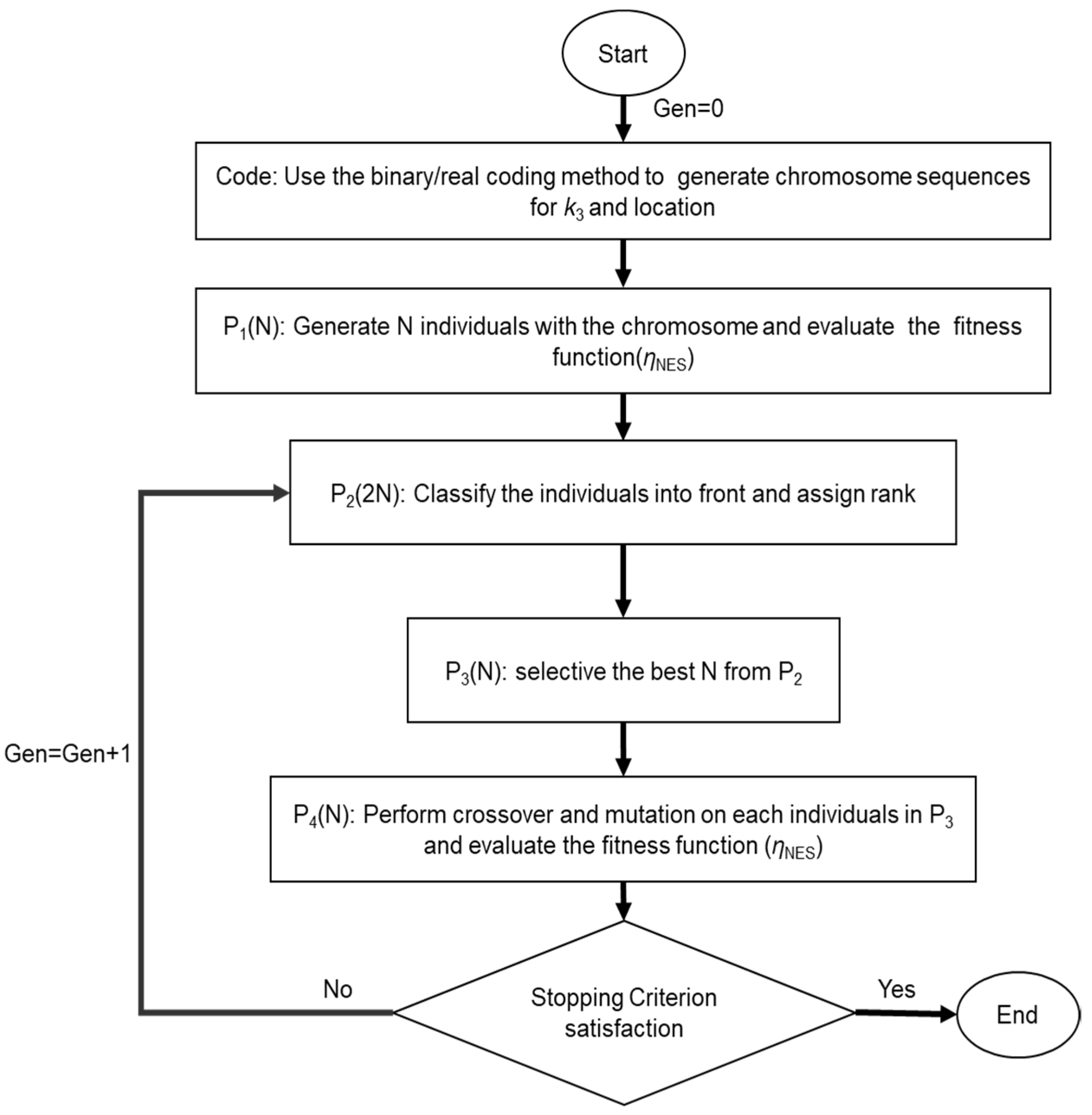
2.2. Optimization
3. Analysis Results
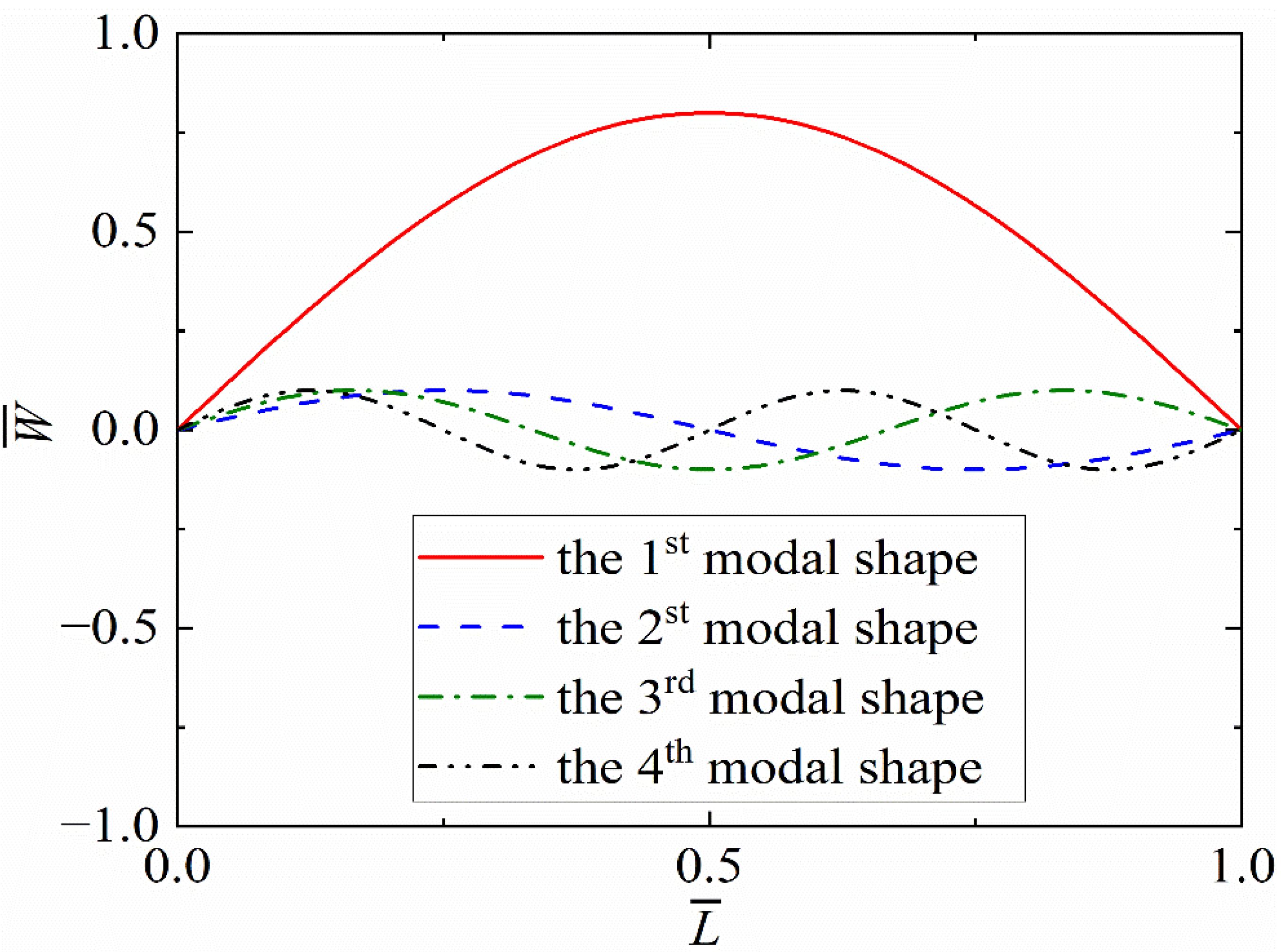
3.1. Modal Analysis
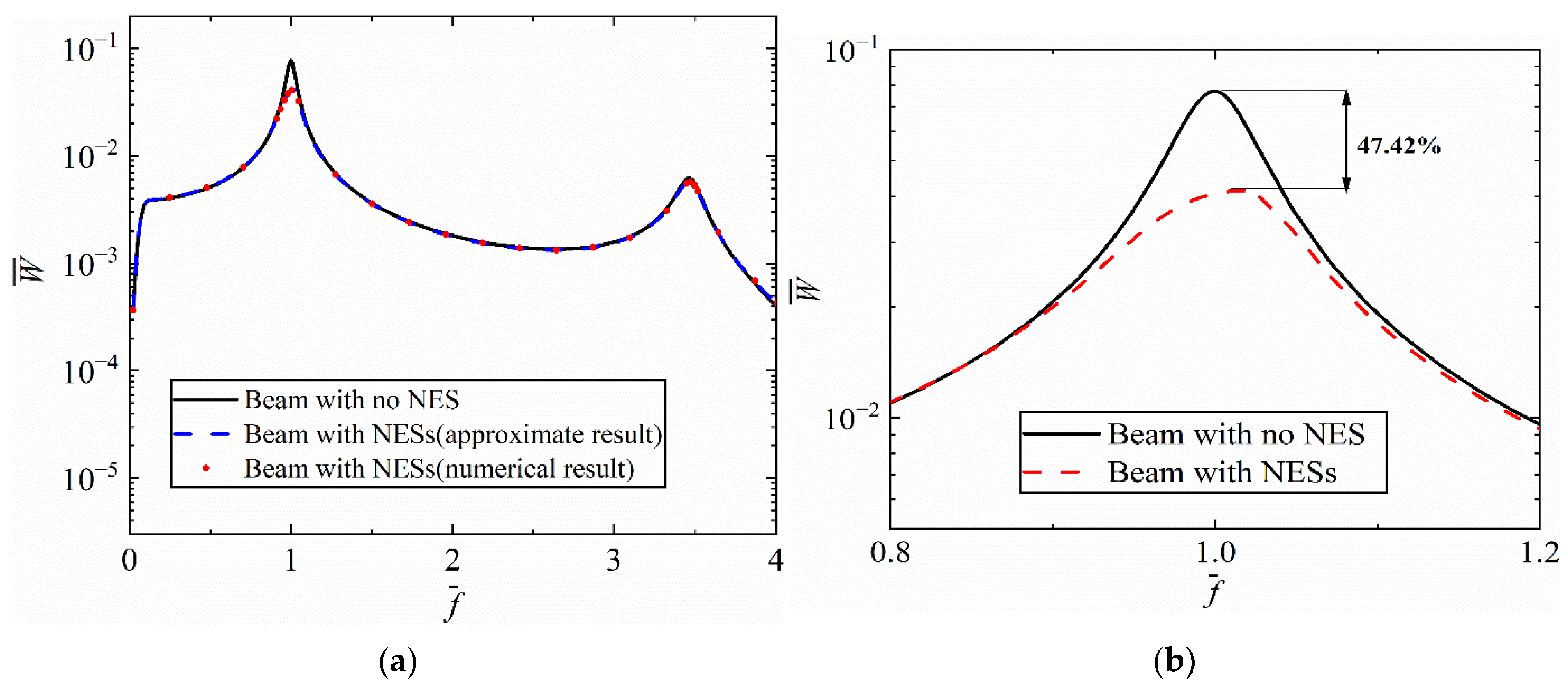
3.2. Vibration Reduction Performance
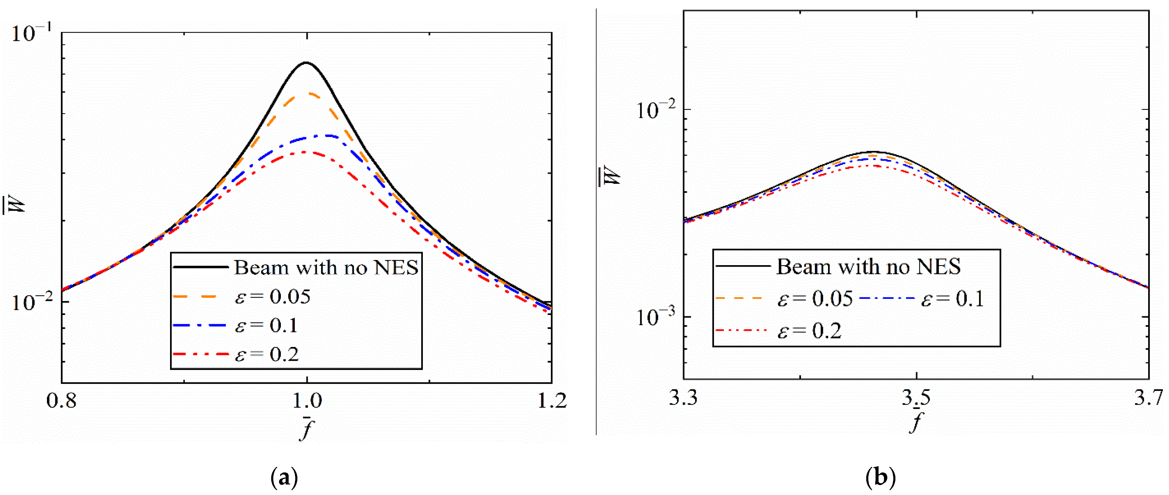
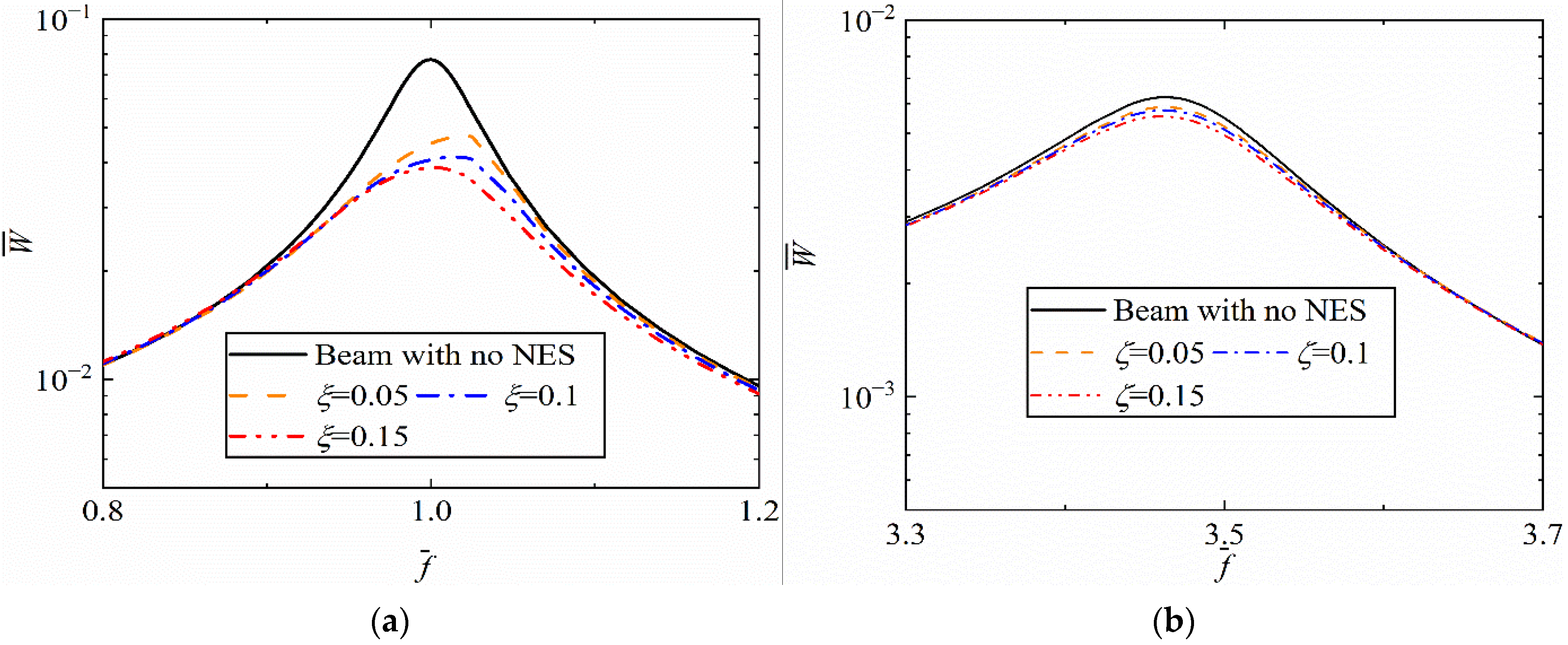
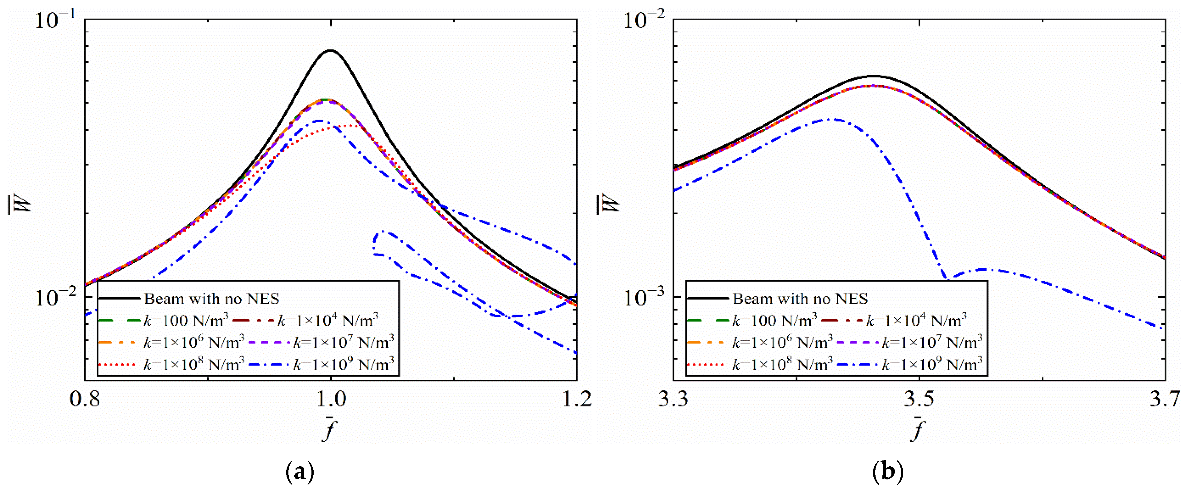
3.3. Parameter Analysis
4. Optimization Results
5. Conclusions
- (1)
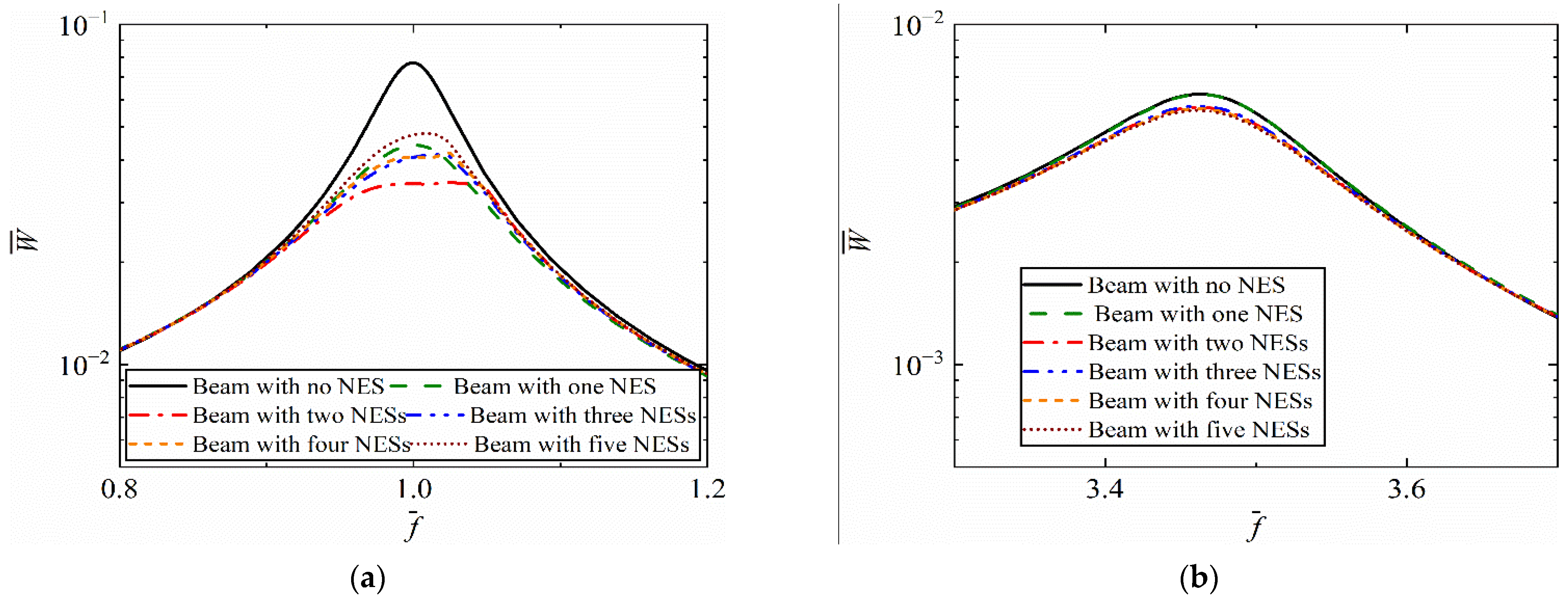
- For a short beam coupled with NESs, it is necessary to establish dynamic models with Timoshenko beam theory. The errors of the first four resonance frequencies based on Timoshenko beam theory were within 1%, while those based on Euler beam theory exceeded 69%. With the same total mass, the multiple parallel nonlinear energy sinks achieved better vibration reduction performance than a single nonlinear energy sink, and the first resonant peak was reduced by 54.55%.
- (2)
- When increasing the mass ratio and damping ratio of NESs, better performance at the first two resonance frequencies can be obtained. When adjusting the cubic stiffness of NESs, effective vibration reduction is obtained within a certain range. Unstable responses occur when the value of cubic stiffness exceeds a threshold.
- (3)
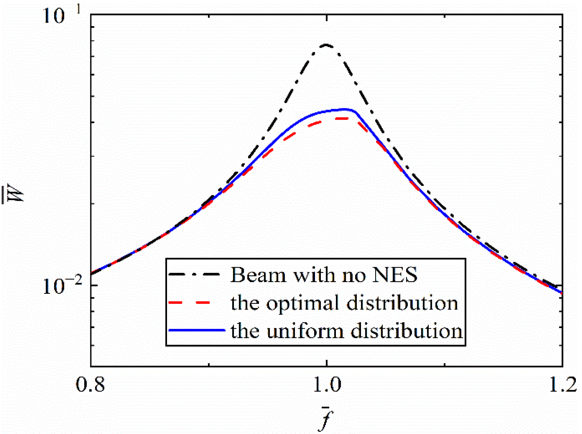
- The optimal locations of multiple parallel NESs are related to low-order modal shapes, and the optimal locations and cubic stiffness are different for different numbers of nonlinear energy sinks. In the studied case, when the number of parallel NESs equaled two, the best performance was obtained. A further increase in the number of NESs may lead to declining effective performance.
Author Contributions
Funding
Institutional Review Board Statement
Informed Consent Statement
Data Availability Statement
Acknowledgments
Conflicts of Interest
References
- Botis, M.F.; Cerbu, C. A method for reducing of the overall torsion for reinforced concrete multi-storey irregular structures. Appl. Sci. 2020, 10, 5555. [Google Scholar] [CrossRef]
- Cheng, L.H.; Lu, J.T.; Li, S.M.; Ding, R.; Xu, K.; Li, X.L. Fusion method and application of several source vibration fault signal spatio-temporal multi-correlation. Appl. Sci. 2021, 11, 4318. [Google Scholar] [CrossRef]
- Lara-Valencia, L.A.; Farbiarz-Farbiarz, Y.; Valencia-González, Y. Design of a tuned mass damper inerter (TMDI) based on an exhaustive search optimization for structural control of buildings under seismic excitations. Shock. Vib. 2020, 2020, 8875268. [Google Scholar] [CrossRef]
- Liu, Y.; Chen, K.; Zhang, Y.; Ma, X.; Wang, L. Low-frequency and large-scale hybrid sound absorption using active force control. Acoust. Aust. 2021, 49, 93–103. [Google Scholar] [CrossRef]
- Li, Z.; Song, Z.; Yuan, W.; He, X. Axially functionally graded design methods for beams and their superior characteristics in passive thermal buckling suppressions. Compos. Struct. 2021, 257, 113390. [Google Scholar] [CrossRef]
- Malhotra, A.; Roy, T.; Matsagar, V. Effectiveness of friction dampers in seismic and wind response control of connected adjacent steel buildings. Shock. Vib. 2020, 2020, 8304359. [Google Scholar] [CrossRef]
- Braga, M.T.; Alves, M.T.S.; Cavalini, A.A.; Steffen, V. Influence of temperature on the passive control of a rotating machine using wires of shape memory alloy in the suspension. Smart Mater. Struct. 2020, 29, 035040. [Google Scholar] [CrossRef]
- Wang, Q.; Zeng, J.; Wu, Y.; Zhu, B. Study on semi-active suspension applied on car body underneath suspended system of high-speed railway vehicle. J. Vib. Control 2020, 26, 671–679. [Google Scholar] [CrossRef]
- Ding, H.; Chen, L.Q. Designs, analysis, and applications of nonlinear energy sinks. Nonlinear Dyn. 2020, 100, 3061–3107. [Google Scholar] [CrossRef]
- Wang, X.; Yang, B.; Guo, S. Nonlinear convergence active vibration absorber for single and multiple frequency vibration control. J. Vib. Control 2017, 411, 289–303. [Google Scholar] [CrossRef]
- Vakakis, A.F. Inducing passive nonlinear energy sinks in vibrating systems. J. Vib. Acoust. 2001, 123, 324–332. [Google Scholar] [CrossRef]
- He, M.X.; Tang, Y.; Ding, Q. Dynamic analysis and optimization of a cantilevered beam with both the acoustic black hole and the nonlinear energy sink. J. Intel. Mat. Syst. Str. 2022, 33, 70–83. [Google Scholar] [CrossRef]
- Li, H.; Li, A.; Kong, X. Design criteria of bistable nonlinear energy sink in steady-state dynamics of beams and plates. Nonlinear Dyn. 2021, 103, 1475–1497. [Google Scholar] [CrossRef]
- Zhang, W.x.; Chen, J.e. Influence of geometric nonlinearity of rectangular plate on vibration reduction performance of nonlinear energy sink. J. Mech. Sci. Technol. 2020, 34, 3127–3135. [Google Scholar] [CrossRef]
- Li, H.; Touzé, C.; Pelat, A.; Gautier, F. Combining nonlinear vibration absorbers and the Acoustic Black Hole for passive broadband flexural vibration mitigation. Int. J. Nonlin. Mech. 2021, 129, 103558. [Google Scholar] [CrossRef]
- Zhou, J.; Xu, M.; Zha, J.; Yang, Z. The suppression of nonlinear panel flutter response at elevated temperatures using a nonlinear energy sink. Meccanica 2021, 56, 41–57. [Google Scholar] [CrossRef]
- de Lima, D.M.; López-Yánez, P.A.; Pereira, M.A. Vibration control device for steel tubular towers of horizontal axis wind turbines. Lat. Am. J. Solids. Struct. 2019, 16, 1–21. [Google Scholar]
- de Pietro, M.; Biferale, L.; Boffetta, G.; Cencini, M. Time irreversibility in reversible shell models of turbulence. Eur. Phys. J. E 2018, 41, 48. [Google Scholar] [CrossRef]
- Zang, J.; Cao, R.Q.; Zhang, Y.W. Steady-state response of a viscoelastic beam with asymmetric elastic supports coupled to a lever-type nonlinear energy sink. Nonlinear Dyn. 2021, 105, 1327–1341. [Google Scholar] [CrossRef]
- Georgiades, F.; Vakakis, A.F. Dynamics of a linear beam with an attached local nonlinear energy sink. Commun. Nonlinear Sci. 2007, 12, 643–651. [Google Scholar] [CrossRef]
- Kani, M.; Khadem, S.E.; Pashaei, M.H.; Dardel, M. Vibration control of a nonlinear beam with a nonlinear energy sink. Nonlinear Dyn. 2016, 83, 1–22. [Google Scholar] [CrossRef]
- Liu, G.; Chen, G.F.; Cui, F.S. Vibration suppression for beam-like repeating lattice structure based on equivalent model by a nonlinear energy sink. Math. Probl. Eng. 2021, 2021, 6659598. [Google Scholar] [CrossRef]
- Chouvion, B. A wave approach to show the existence of detached resonant curves in the frequency response of a beam with an attached nonlinear energy sink. Mech. Res. Commun. 2019, 95, 16–22. [Google Scholar] [CrossRef]
- Zhang, Y.W.; Zang, J.; Yang, T.Z.; Fang, B.; Wen, X. Vibration suppression of an axially moving string with transverse wind loadings by a nonlinear energy sink. Math. Probl. Eng. 2013, 2013, 348042. [Google Scholar] [CrossRef]
- Zhang, Y.W.; Hou, S.; Zhang, Z.; Zang, J.; Ni, Z.Y.; Teng, Y.Y.; Chen, L.Q. Nonlinear vibration absorption of laminated composite beams in complex environment. Nonlinear Dyn. 2020, 99, 2605–2622. [Google Scholar] [CrossRef]
- Vaurigaud, B.; Savadkoohi, A.T.; Lamarque, C.H. Targeted energy transfer with parallel nonlinear energy sinks. Part I: Design theory and numerical results. Nonlinear Dyn. 2011, 66, 763–780. [Google Scholar] [CrossRef]
- Savadkoohi, A.T.; Vaurigaud, B.; Lamarque, C.H.; Pernot, S. Targeted energy transfer with parallel nonlinear energy sinks, part II: Theory and experiments. Nonlinear Dyn. 2012, 67, 37–46. [Google Scholar] [CrossRef]
- Zhang, Y.W.; Zhang, Z.; Chen, L.Q.; Yang, T.Z.; Fang, B.; Zang, J. Impulse-induced vibration suppression of an axially moving beam with parallel nonlinear energy sinks. Nonlinear Dyn. 2015, 82, 61–71. [Google Scholar] [CrossRef]
- Chen, J.E.; He, W.; Zhang, W.; Yao, M.H.; Liu, J.; Sun, M. Vibration suppression and higher branch responses of beam with parallel nonlinear energy sinks. Nonlinear Dyn. 2018, 291, 885–904. [Google Scholar] [CrossRef]
- Li, C.; Chen, G.; Fang, B.; Zang, J.; Zhang, Y. Vibration control for lever-type parallel nonlinear energy trap. J. Vib. Shock. 2021, 40, 54–64. [Google Scholar]
- Mamaghani, A.E.; Khadem, S.E.; Bab, S.; Pourkiaee, S.M. Irreversible passive energy transfer of an immersed beam subjected to a sinusoidal flow via local nonlinear attachment. Int. J. Mech. Sci. 2018, 138, 427–447. [Google Scholar] [CrossRef]
- Kani, M.; Khadem, S.E.; Pashaei, M.H.; Dardel, M. Design and performance analysis of a nonlinear energy sink attached to a beam with different support conditions. J. Mech. Eng. Sci. 2016, 230, 527–542. [Google Scholar] [CrossRef]
- Khazaee, M.; Khadem, S.E.; Moslemi, A.; Abdollahi, A. A comparative study on optimization of multipleple essentially nonlinear isolators attached to a pipe conveying fluid. Mech. Syst. Signal. Process. 2020, 141, 106442. [Google Scholar] [CrossRef]
- Georgiades, F.; Vakakis, A.F. Passive targeted energy transfers and strong modal interactions in the dynamics of a thin plate with strongly nonlinear attachments. Int. J. Solids Struct. 2009, 46, 2330–2353. [Google Scholar] [CrossRef]
- Bab, S.; Khadem, S.E.; Mahdiabadi, M.K.; Shahgholi, M. Vibration mitigation of a rotating beam under external periodic force using a nonlinear energy sink (NES). J. Vib. Control 2017, 23, 1001–1025. [Google Scholar] [CrossRef]
- Schnabl, S.; Saje, M.; Turk, G.; Planinc, I. Analytical solution of two-layer beam taking into account interlayer slip and shear deformation. J. Struct. Eng. 2007, 133, 886–894. [Google Scholar] [CrossRef]

| Order | Timoshenko Theory (Error) | Euler Theory (Error) |
|---|---|---|
| 1st | 43.94 Hz (0.06%) | 46.92 Hz (6.71%) |
| 2nd | 152.75 Hz (0.24%) | 187.72 Hz (22.89%) |
| 3rd | 292.15 Hz (0.34%) | 423.33 Hz (44.90%) |
| 4th | 440.24 Hz (0.35%) | 747.96 Hz (69.90%) |
| Iteration | di (m) | The 1st Peak | Reduction | The 2nd Peak | Reduction |
|---|---|---|---|---|---|
| 0 | / | 0.077 | / | 0.0062 | / |
| 1 | [0.35, 0.75, 0.8] | 0.044 | 42.86% | 0.0058 | 7.05% |
| 2 | [0.45, 0.5, 0.8] | 0.042 | 45.45% | 0.0058 | 7.05% |
| 3 | [0.5, 0.6, 0.75] | 0.040 | 48.05% | 0.0057 | 8.06% |
| 4 | [0.5, 0.6, 0.75] | 0.040 | 48.05% | 0.0057 | 8.06% |
| Distribution | di (m) | The 1st Peak | Reduction | The 2nd Peak | Reduction |
|---|---|---|---|---|---|
| No NES | / | 0.077 | / | 0.0062 | / |
| Optimal | [0.5, 0.6, 0.75] | 0.040 | 48.05% | 0.0057 | 8.06% |
| Uniform | [0.25, 0.5, 0.75] | 0.044 | 42.86% | 0.0056 | 9.67% |
| N | di (m) | k3 (N/m3) | The 1st Peak | Reduction | The 2nd Peak | Reduction |
|---|---|---|---|---|---|---|
| 0 | / | / | 0.077 | / | 0.0062 | / |
| 1 | [0.5] | 1.9 × 10⁹ | 0.044 | 42.85% | 0.0062 | 0.03% |
| 2 | [0.5, 0.75] | 4.1 × 10⁸ | 0.035 | 54.55% | 0.0058 | 6.54% |
| 3 | [0.5, 0.6, 0.75] | 9.0 × 10⁷ | 0.040 | 48.05% | 0.0057 | 8.06% |
| 4 | [0.2, 0.25, 0.6, 0.75] | 7.0 × 10⁷ | 0.041 | 46.75% | 0.0056 | 8.06% |
| 5 | [0.05, 0.5, 0.75, 0.8, 0.95] | 4.0 × 10⁷ | 0.046 | 40.25% | 0.0055 | 11.29% |
Publisher’s Note: MDPI stays neutral with regard to jurisdictional claims in published maps and institutional affiliations. |
© 2022 by the authors. Licensee MDPI, Basel, Switzerland. This article is an open access article distributed under the terms and conditions of the Creative Commons Attribution (CC BY) license (https://creativecommons.org/licenses/by/4.0/).
Share and Cite
Zhang, W.-Y.; Niu, M.-Q.; Chen, L.-Q. Vibration Reduction of a Timoshenko Beam with Multiple Parallel Nonlinear Energy Sinks. Appl. Sci. 2022, 12, 9008. https://doi.org/10.3390/app12189008
Zhang W-Y, Niu M-Q, Chen L-Q. Vibration Reduction of a Timoshenko Beam with Multiple Parallel Nonlinear Energy Sinks. Applied Sciences. 2022; 12(18):9008. https://doi.org/10.3390/app12189008
Chicago/Turabian StyleZhang, Wen-Yong, Mu-Qing Niu, and Li-Qun Chen. 2022. "Vibration Reduction of a Timoshenko Beam with Multiple Parallel Nonlinear Energy Sinks" Applied Sciences 12, no. 18: 9008. https://doi.org/10.3390/app12189008
APA StyleZhang, W.-Y., Niu, M.-Q., & Chen, L.-Q. (2022). Vibration Reduction of a Timoshenko Beam with Multiple Parallel Nonlinear Energy Sinks. Applied Sciences, 12(18), 9008. https://doi.org/10.3390/app12189008