Article

Evaluation of the Flexural Rigidity of Underground Tanks Manufactured by Rotomolding

Department of Production Engineering, Faculty of Technology, Tomas Bata University in Zlín, Vavrečkova 5669, 76001 Zlín, Czech Republic
*
Author to whom correspondence should be addressed.
Appl. Sci. 2022, 12(18), 9276; https://doi.org/10.3390/app12189276
Submission received: 31 August 2022 / Revised: 12 September 2022 / Accepted: 14 September 2022 / Published: 15 September 2022
(This article belongs to the Section Applied Industrial Technologies)

Abstract

:
This study focuses on the flexural properties of the layered wall structures of plastic tanks produced by rotational molding technology. The aim was to assess the possibility of replacing the homogeneous walls of rotationally cast large-volume underground tanks with structural walls for stability and warpage prevention. The possibilities of material saving by combining lightweight and non-lightweight tank wall layers were investigated. By applying the engineering theory of bending inhomogeneous layered walls, the flexural rigidity values of the walls of the tanks of different structures were determined. The values of the flexural rigidity of the tank wall samples produced by rotomolding technology were determined experimentally. Moreover, a comparison of the calculated and experimentally determined flexural rigidity values of the layered walls and optimization of these structures was carried out. In the case under study, it was theoretically and experimentally confirmed that the optimum ratio of compact layer thickness versus total wall thickness is given by the resulting value: t1OPT = 0.189 h.

1. Introduction

Every successful application of thermoplastics is conditioned by a qualified determination of the dimensions and shape of the proposed structure in addition to thorough design and technological preparation. Thermoplastics are generally relatively low in stiffness and strength, have a significant tendency to creep, a high thermal expansion, and a marked dependence on temperature as regards their mechanical characteristics. These properties usually appear to be disadvantageous. On the other hand, however, there are undeniable advantages to this, for example, ease of processing, low energy consumption, high manufacturing productivity, and the wide range of applicable new technologies. Furthermore, it is the excellent resistance to aggressive substances and environments that makes thermoplastics suitable for the construction of equipment operating in harsh operating [1,2] conditions, e.g., in the chemical and food industries.
The specific mechanical behavior of thermoplastics brings with it peculiarities and difficulties for design compared to conventional materials. The nature of the technology and the desire to limit the weight and cost of the product lead to the design of thermoplastic structures with thin walls. Due to low stiffness values (modulus of elasticity) or time-dependent stiffness (modulus of creep), deformation states rather than yield states are often decisive in product design [3,4]. Thus, very often, the limit states are decisive, causing a loss of structural stability.
In the industry, the current issues are the assessment of the possibility of replacing the homogeneous walls of rotationally cast large-volume underground tanks [5,6] with structural walls [7,8,9], to promote flexural rigidity and, therefore, stability capacity. It is necessary to investigate the possibilities of potential material savings by combining lightweight and non-lightweight layers of the tank wall, thus creating three-layer sandwich walls. This implies the need for computational predictions of the flexural rigidity values of tank walls for different wall structure concepts.
Although the topic of underground tanks produced using rotomolding technology is very current, as we observed in the relevant review, there is no practical attention paid to this issue in the literature. Many authors address potential problems such as strength, the failure mechanism, and structural vessel optimization [10,11]. Carrera [12] reported that functionally graded material (FGM) layers are convenient to reduce shear and normal stress gradients. Furthermore, the FGM layers lead to benefits in terms of the buckling load; however, the use of FGM requires different manufacturing technology to that explored in this study. In the case of ground or underground horizontal cylindrical tanks, the wall of the cylindrical shell of a tank is subject to non-homogeneous stress. As Magnucki [13] states, the regions where compression occurs, buckling becomes possible. It was found that, for underground and above-ground tanks with similar loads, the critical thickness of the wall of underground tanks exceeds that of their above-ground counterparts. In the study of Brar [14], he statistically evaluates the random geometric imperfection stability for an asymmetrical cylindrical vessel under external pressure, while the relevant EN standard controls the relevant safety at the limit of the stability capacity with respect to geometric imperfections. In [15], the authors focus on electrolyte and recirculation tanks considering the technology itself but not the stability, confirming the need for safe rigidly stable tanks, although this is outside of the scope of our study.
On the basis of the application of the technical theory of bending of inhomogeneous layered walls, the flexural rigidity values of tank walls for individual concepts of the wall structure (a homogeneous, three-layer sandwich structure) were computationally determined. The values of flexural rigidity of tank wall samples manufactured using rotomolding technology were experimentally determined. The intention of the study was to compare the calculated and experimentally determined values of the flexural rigidity of layered walls.

2. Materials and Methods

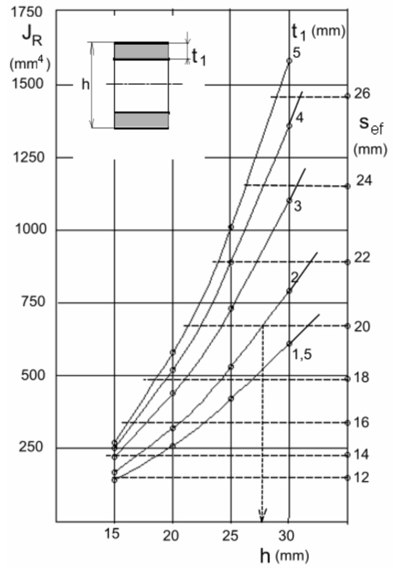
Flexural Rigidity of the Sandwich Structure

It is inappropriate to design bent elements with a full homogeneous cross-section in terms of the efficient use of material. In fact, the area near the neutral surface is only stressed slightly compared to the stresses on the outermost fibers of the cross-section. High stiffness with minimum weight can be achieved by using a three-layer sandwich wall section. The outer layer and rigid layers are separated by a lightweight foam core of low stiffness, shown in Figure 1. For the flexural rigidity of the layered composite cross-section, the engineering theory of bending of composite elements generally applies the following rule:
K0 = E1 JR
where E1 is the modulus of the elasticity of the surface layers, and JR denotes the quadratic moment of the reduced cross-sectional area, as shown in Figure 1a.
For the value of the quadratic moment of the reduced cross-sectional area from Figure 1a, the following relation can be obtained:
J R = 2 [ 1 12 b t 1 3 + t 1 b ( ( h t 1 ) 3 ) 4 ] + [ 1 12 E 2 E 1 b ( h 2 t 1 ) 3 ]
A sandwich structure of given dimensions ti and h substitutes a homogeneous layer of a certain thickness for its flexural rigidity value. We call this the effective thickness of the sandwich wall, sef; see Figure 1b. The effective thickness of the sandwich wall is thus given by the equality of the flexural rigidities according to Figure 1b.
E1 JR = E1 Jef
where Jef is the quadratic moment of the area of a homogeneous (single-layer) wall section of thickness sef, given by
Jef = b sef3/12
It is, therefore,
sef = (12 JR/b)3
The second possibility, especially for cases in which the evaluation of experimental results is required, is to introduce the concept of the effective modulus of elasticity of the sandwich structure. We define this as the modulus of elasticity of an ideally homogeneous (single-layer) wall of an identical thickness to that of the sandwich, with the same value of flexural rigidity as the sandwich structure. According to Figure 1c, this condition is
E e f = E 1 12 J R b h 3
The dependences of the effective thickness sef and the reduced square moment JR on the dimensions of the sandwich structure are plotted in Figure 2. The diagram is constructed for the limiting case E2/E1 << 1, i.e., assuming neglect of the effect of the stiffness of the as-cast layer on the resulting flexural rigidity. This assumption is justified not only by the relatively small value of the modulus of elasticity of the lightweight middle layer, but also by the fact that the bending stresses in the region of the neutral surface of the bent element are low.
Due to the generally low values of flexural rigidity of walls of shell structures made of thermoplastics and their dependence on the loading time and temperature, there is often a real danger of a limit state of loss of stability of the thin-walled shell of the tank, manifested by its buckling and subsequent collapse [15,16,17,18,19]. As follows from the presented parametric study, it is necessary to pay increased attention to the problem of the stability of thermoplastic shells during their structural design.
For the study of sandwich structures, the LLDPE butene-type material (a linear low-density copolymer of polyethylene with butene) from Gerbaldo Polimeri s.p.a (Italy), used in rotational molding technology, under the trade name MICROLEX RM 1242 WT, was chosen, with an MFI = 4 g/10 min and a density of 0.938 g/cm3.

3. Results

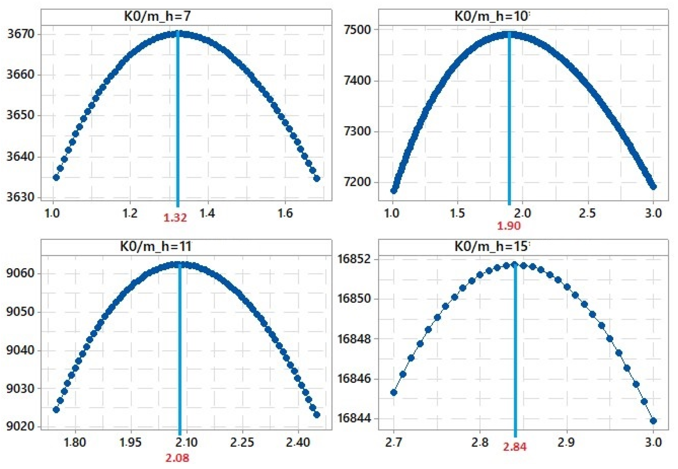
3.1. Optimization of Sandwich Structures

As can be seen from the diagram in Figure 2, a homogeneous wall of a given sef thickness can be replaced by structures with different geometries. Moreover, larger heights h at lower surface layer thicknesses t1 can be chosen, or conversely, thicker surface layers at lower sandwich heights h can be chosen. According to the diagram, for example, a homogeneous wall with a thickness of 20 mm will correspond to structures from t1 = 5 mm, h = 22 mm to t1 = 1.5 mm at h = 32 mm. In general, with increasing layer values t1, the material utilization and thus the effect of the sandwich structure decreases, due to higher material volumes near the neutral axis. The value of the flexural rigidity can be expressed by Equations (1) and (2). If we denote ρ1 as the density of the non-lightweight bearing layers, and ρ2 as the density of the lightweight core, the mass per unit length of the member is given by
m = b [ h ρ 2 + 2 t 1 ( ρ 1 ρ 2 ) ]
Finding the optimum thickness of the outer layers t1 for a certain height h in terms of flexural rigidity obviously means finding the extremum of the function K0/m. For the modulus of elasticity of the non-lightweight material of E1 = 680 MPa, the modulus of elasticity of the lightweight core of E2 = 170 MPa, and a degree of relative volume lightweighting of the core of 50%, the result of the optimization of the investigated structures is given in the diagram in Figure 3.
Table 1 shows the resulting optimum wall thickness values of the non-lightweight layers t1OPT for the considered structures. Naturally, the t1OPT/h ratio is constant. For a given material composition of the structure, t1OPT = 0.189 × h.
For each structure, the theoretical values of the effective modulus of elasticity according to Equation (6) were compared with those determined experimentally. The results are shown in Table 2.
It is clear from Table 2 that the experimental values are, in all cases, only insignificantly lower than the theoretical values. Thus, as can be seen, for the practical purposes of predicting the replacement of a homogeneous single-layer wall with a three-layer structure, the theoretical values can be used as a qualified estimate of the flexural rigidity of a given sandwich structure, with 7.07% of maximum difference. The value of the effective thickness of the homogeneous single-layer wall was used to assess the suitability of replacing the homogeneous single-layer wall with a layered structure. The effective thicknesses calculated from the experimental Eef values are given in Table 3.
The degree of efficiency of replacing the homogeneous wall with a three-layer wall is also evident from the comparison of material consumption. Let us denote the effective mass, i.e., the unit mass of a homogeneous wall of effective thickness sef, as
m ef = b   s ef   ρ 1
Comparisons of the effective mass of the homogeneous wall’s effective thickness mef with the effective mass of the structures considered are given in Table 3. As can be seen, the most efficient structure is clearly structure 3v_15. Structures 3v_7 and 3v_10 can no longer be recommended due to the small material savings. This is due to the fact that structures 3v_7 and 3v_10 achieve seemingly high sef values, but uneconomically, at the cost of considerable thicknesses of the surface layers t1. This means that they are similar to a homogeneous wall.

3.2. Stability of Shell Structures

The existence of compressive stresses in the walls of thin-walled shell-type structures generally means there is a risk of loss of stability of the structure. This danger of sudden significant deformation and the possibility of subsequent collapse is compounded in the case of plastic structures as a result of their generally low flexural rigidity. In practice, it is, therefore, necessary to consider the case of external loading effects causing compressive stresses in the thin-walled shell.
In practice [20,21], these are mainly cases of underground plastic tanks, such as sewage treatment plants, septic tanks, storage tanks, etc.
In these applications, there are generally two main load cases to be considered. These are the emergency, short-term cases of an empty tank, being loaded only by the external pressure of the backfill, and the long-term operational case. The operational load case is determined by the superposition of the internal hydrostatic pressure with a certain water level and the external pressure exerted by the containment.
The short-term empty tank load case is obviously unfavorable because of the absence of internal filling pressure, but the relatively large value of the design modulus of elasticity, equal to the short-term value of the creep modulus, plays a favorable role. However, because of the viscoelastic behavior of thermoplastics, the duration of this condition must be limited to the relatively short time necessary to carry out maintenance or repair.
While the long-term, service load case is advantageous due to the internal hydrostatic pressure of the container filling, the calculated modulus of elasticity equal to the long-term creep modulus is, on the other hand, very low. If insufficient attention is paid to stability issues, a limit state of loss of stability is often reached resulting in the collapse of the tank shell; see an example of an accident in Figure 4.
An example of the result of FEM modelling on the loss of stability of an underground tank is shown in Figure 5. The ultimate load of real tanks is always lower due to geometric inaccuracies in the tank shape, variability in wall thickness or local weakening, residual stresses, unevenness of the backfill load during tank installation, and the possible effects of groundwater, rainfall, and other aspects related to both installation and operation.
In practice, these aspects are taken into account by the relevant safety value [22,23,24,25] for the limit state of loss of stability, which is usually given by the relevant standard.

4. Conclusions

Due to the generally low values of the flexural rigidity of walls of shell structures made of thermoplastics and their dependence on the loading time and temperature, there is a very real danger of a limit state of loss of stability of the thin-walled shell, manifested by its buckling and subsequent collapse. As follows from the presented parametric study, it is necessary to pay increased attention to the problem of the stability of thermoplastic shells and, therefore, to the appropriate value of the wall flexural rigidity in their structural design. This can prevent possible failures in the practical applications of these types of structures.

Author Contributions

Data curation and Visualization, V.P.; Funding acquisition and Methodology, M.K.; Investigation and Writing—original draft, O.Š.; Supervision and Writing—review & editing, O.B.; Validation, D.M. All authors have read and agreed to the published version of the manuscript.

Funding

This research received no external funding.

Institutional Review Board Statement

Not applicable.

Informed Consent Statement

Not applicable.

Data Availability Statement

Not applicable.

Conflicts of Interest

The authors declare no conflict of interest.

Nomenclature

bcross-sectional width of the sandwich element
E1calculated modulus of elasticity—non-lightweight layers
E2calculated modulus of elasticity—lightweight layer (core)
Eefeffective modulus of elasticity
Eef theoreticaltheoretical effective modulus of elasticity
Eef experimentalexperimental effective modulus of elasticity
hcross-sectional height of the sandwich element
JRquadratic modulus of the reduced cross-sectional area
Jefeffective quadratic modulus of the cross-section of the sandwich element
K0flexural rigidity of the cross-section of the sandwich element
munit mass of the sandwich structure
mefunit mass of the homogeneous wall of effective thickness
sefeffective thickness of the sandwich structure
t1thickness of surface—non-lightweight layers
t1OPToptimum thickness of the surface—non-lightweight layers
ρ1density of the non-lightweight layers
ρ2density of the lightweight core

References

  1. Černohlávek, V.; Štěrba, J.; Svoboda, M.; Zdráhal, T.; Suszyński, M.; Chalupa, M.; Krobot, Z. Verification of the Safety of Storing a Pair of Pressure Vessels. Manuf. Technol. 2022, 21, 762–773. [Google Scholar] [CrossRef]
  2. Daghighi, S.; Weaver, P.M. Three-dimensional effects influencing failure in bend-free, variable stiffness composite pressure vessels. Compos. Struct. 2021, 262, 113346. [Google Scholar] [CrossRef]
  3. Margolis, J.M. Engineering Thermoplastics: Properties and Applications; CRC Press: Boca Raton, FL, USA, 2020. [Google Scholar]
  4. Shaker, R.; Rodrigue, D. Rotomolding of Thermoplastic Elastomers Based on Low-Density Polyethylene and Recycled Natural Rubber. Appl. Sci. 2019, 9, 5430. [Google Scholar] [CrossRef]
  5. Crawford, R.J.; Throne, J.L. Rotational Molding Technology; William Andrew Publishing: New York, NY, USA, 2001. [Google Scholar]
  6. Novo, A.V.; Bayon, J.R.; Castro-Fresno, D.; Rodriguez-Hernandez, J. Review of Seasonal Heat Storage in Large Basins: Water Tanks and Gravel–Water Pits. Appl. Energy 2010, 87, 390–397. [Google Scholar] [CrossRef]
  7. Tkac, J.; Samborski, S.; Monkova, K.; Debski, H. Analysis of mechanical properties of a lattice structure produced with the additive technology. Comp. Struct. 2020, 242, 112138. [Google Scholar] [CrossRef]
  8. Xue, B.; Peng, Y.X.; Ren, S.F.; Liu, N.N.; Zhang, Q. Investigation of impact resistance performance of pyramid lattice sandwich structure based on SPH-FEM. Comp. Struct. 2021, 261, 113561. [Google Scholar] [CrossRef]
  9. Saifullah, A.; Wang, L.; Barouni, A.; Giasin, K.; Lupton, C.; Jiang, C.; Zhang, Z.; Quaratino, A.; Dhakal, H.N. Low Velocity Impact (LVI) and Flexure-after-Impact (FAI) Behaviours of Rotationally Moulded Sandwich Structures. J. Mater. Res. Technol. 2021, 15, 3915–3927. [Google Scholar] [CrossRef]
  10. Błachut, J.; Magnucki, K. Strength, stability, and optimization of pressure vessels: Review of selected problems. Appl. Mech. Rev. 2008, 61, 060801. [Google Scholar] [CrossRef]
  11. Renhuai, L.; Jianghong, X. Development of nonlinear mechanics for laminated composite plates and shells. Chin. J. Theor. Appl. Mech. 2017, 49, 487–506. [Google Scholar] [CrossRef]
  12. Carrera, E.; Soave, M. Use of functionally graded material layers in a two-layered pressure vessel. J. Press. Vessel Technol. 2011, 133, 051202. [Google Scholar] [CrossRef]
  13. Magnucki, K.; Stasiewicz, P. Critical sizes of ground and underground horizontal cylindrical tanks. Thin-Walled Struct. 2003, 41, 317–327. [Google Scholar] [CrossRef]
  14. Brar, G.S.; Hari, Y.; Williams, D.K. Calculation of working pressure for cylindrical vessel under external pressure. In Proceedings of the ASME 2010 Pressure Vessels and Piping Division/K-PVP Conference, Bellevue, Washington, DC, USA, 18–22 July 2010. [Google Scholar] [CrossRef]
  15. Subbaiah, T.; Vijetha, P.; Marandi, B.; Sanjay, K.; Minakshi, M. Ionic Mass Transfer at Point Electrodes Located at Cathode Support Plate in an Electrorefining Cell in Presence of Rectangular Turbulent Promoters. Sustainability 2022, 14, 880. [Google Scholar] [CrossRef]
  16. Banghai, J.; Zhibin, L.; Fangyun, L. Failure mechanism of sandwich beams subjected to three-point bending. Comp. Struct. 2015, 133, 739–745. [Google Scholar] [CrossRef]
  17. Behravan, A.; Dejong, M.M.; Brand, A.S. Laboratory Study on Non-Destructive Evaluation of Polyethylene Liquid Storage Tanks by Thermographic and Ultrasonic Methods. CivilEng 2021, 2, 823–851. [Google Scholar] [CrossRef]
  18. Yang, L.; Chen, Z.; Chen, F.; Guo, W.; Cao, G. Buckling of cylindrical shells with general axisymmetric thickness imperfections under external pressure. Eur. J. Mech. A/Solids 2013, 38, 90–99. [Google Scholar] [CrossRef]
  19. Yang, L.; Luo, Y.; Qiu, T.; Zheng, H.; Zeng, P. A novel analytical study on the buckling of cylindrical shells subjected to arbitrarily distributed external pressure. Eur. J. Mech. A/Solids 2022, 91, 104406. [Google Scholar] [CrossRef]
  20. Jiroutova, D. Methodology of Experimental Analysis of Long-Term Monitoring of Sandwich Composite Structure by Fibre-Optic Strain Gauges. Manuf. Technol. 2016, 16, 512–518. [Google Scholar] [CrossRef]
  21. Beall, G.L. Rotational Molding: Design, Materials, Tooling, and Processing; Hanser: Munich, Germany, 1998. [Google Scholar]
  22. Scott, D. Products and Applications—Composite and Thermoplastic Tanks, Silos and Other Vessels. Adv. Mater. Water Handl. 2000, 175–216. [Google Scholar] [CrossRef]
  23. Beňo, P.; Kozak, D.; Konjatić, P. Optimization of thin-walled constructions in CAE system ANSYS. Tech. Gaz. 2014, 21, 1051–1055. [Google Scholar]
  24. Mešić, E.; Muratović, E.; Redžepagić-Vražalica, L.; Pervan, N.; Muminović, A.J.; Delić, M.; Glušac, M. Experimental & FEM analysis of orthodontic mini-implant design on primary stability. Appl. Sci. 2021, 11, 5461. [Google Scholar] [CrossRef]
  25. Regassa, Y.; Gari, J.; Lemu, H.G. Composite Overwrapped Pressure Vessel Design Optimization Using Numerical Method. J. Compos. Sci. 2022, 6, 229. [Google Scholar] [CrossRef]
Figure 1. Reduced sandwich structure area (a), effective thickness (b), and effective modulus (c).
Applsci 12 09276 g001
Figure 2. Dependence of the effective thickness and reduced square moment on the dimensions of the sandwich structure.
Applsci 12 09276 g002
Figure 3. Resulting optimum thicknesses of the surface layers of the individual structures.
Applsci 12 09276 g003
Figure 4. Example of loss of stability of an underground reservoir produced by rotomolding technology.
Applsci 12 09276 g004
Figure 5. Example of the result of FEM modelling of the stability capacity of an underground tank loaded with soil pressure.
Applsci 12 09276 g005
Table 1. Optimum wall thickness for structures with non-lightweight layers.
Structureh (mm)t1 (mm)t1OPT (mm)
3v_772.41.32
3v_10102.51.90
3v_11111.62.08
3v_15152.02.84
Table 2. Comparison of calculated effective modulus of elasticity with experimental value.
StructureEef theoretical (MPa)Eef experimental (MPa)Difference δ (%)
3v_76786405.94
3v_106125766.25
3v_114504226.64
3v_154243967.07
Table 3. Effective weight of the structures.
Structuresef (mm)msef/m3v (-)
3v_76.71.21
3v_108.91.12
3v_119.11.42
3v_1512.11.64
Publisher’s Note: MDPI stays neutral with regard to jurisdictional claims in published maps and institutional affiliations.

