
Finite Element Parametric Analysis of High-Strength Eccentrically Braced Steel Frame with Variable-Cross-Section Replaceable Link

Abstract
:1. Introduction
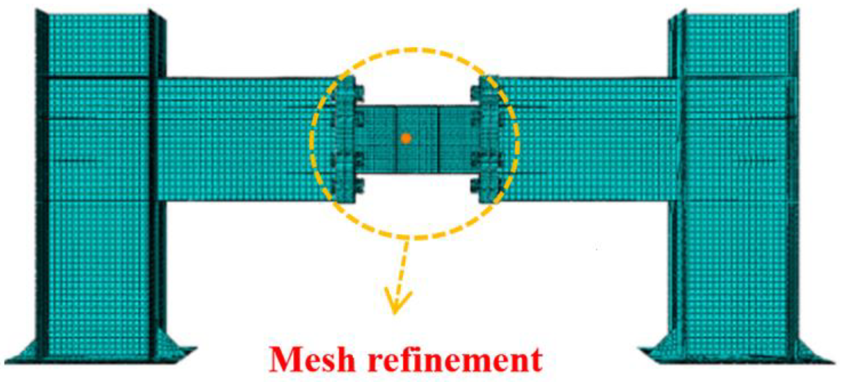
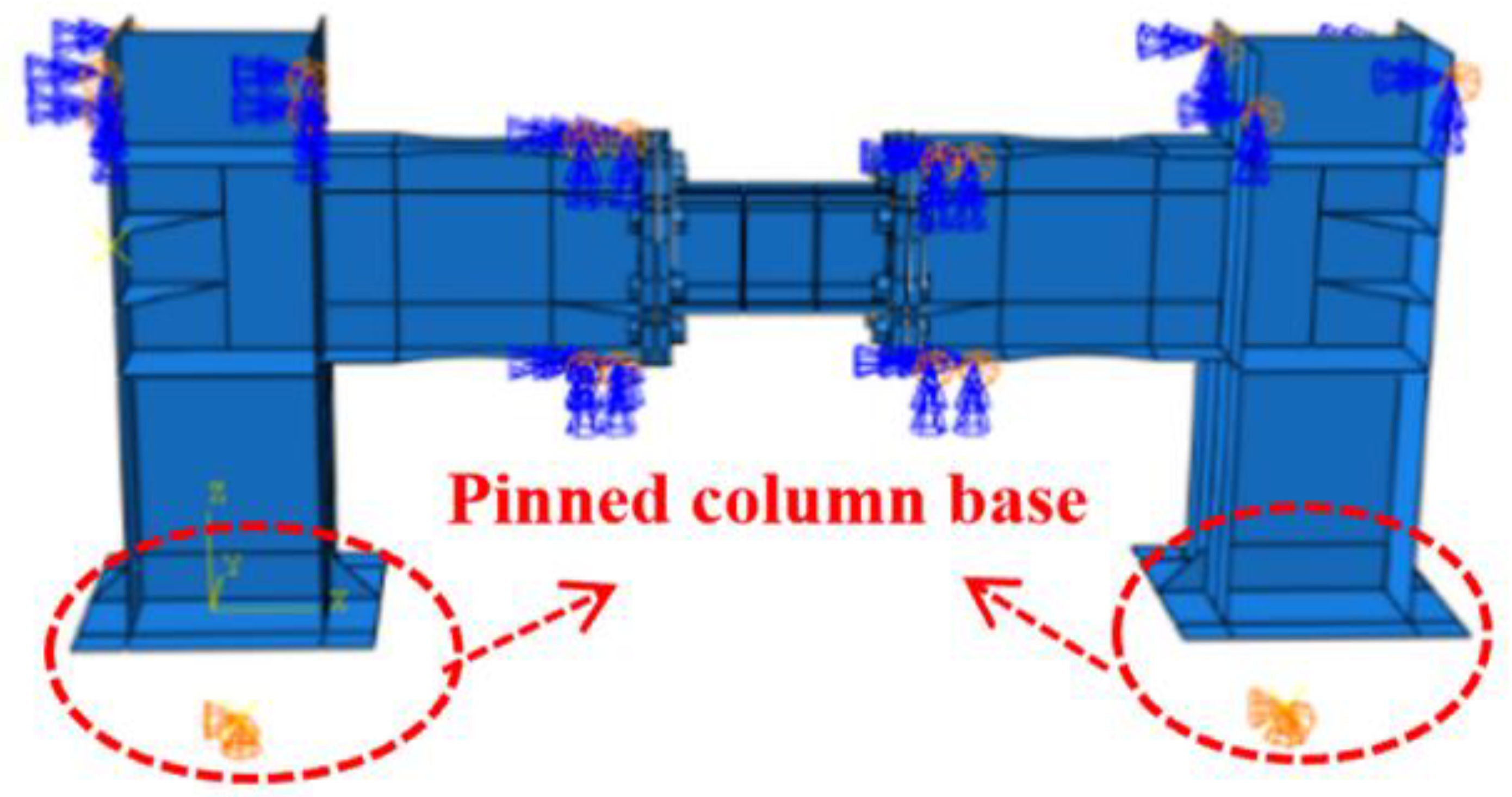
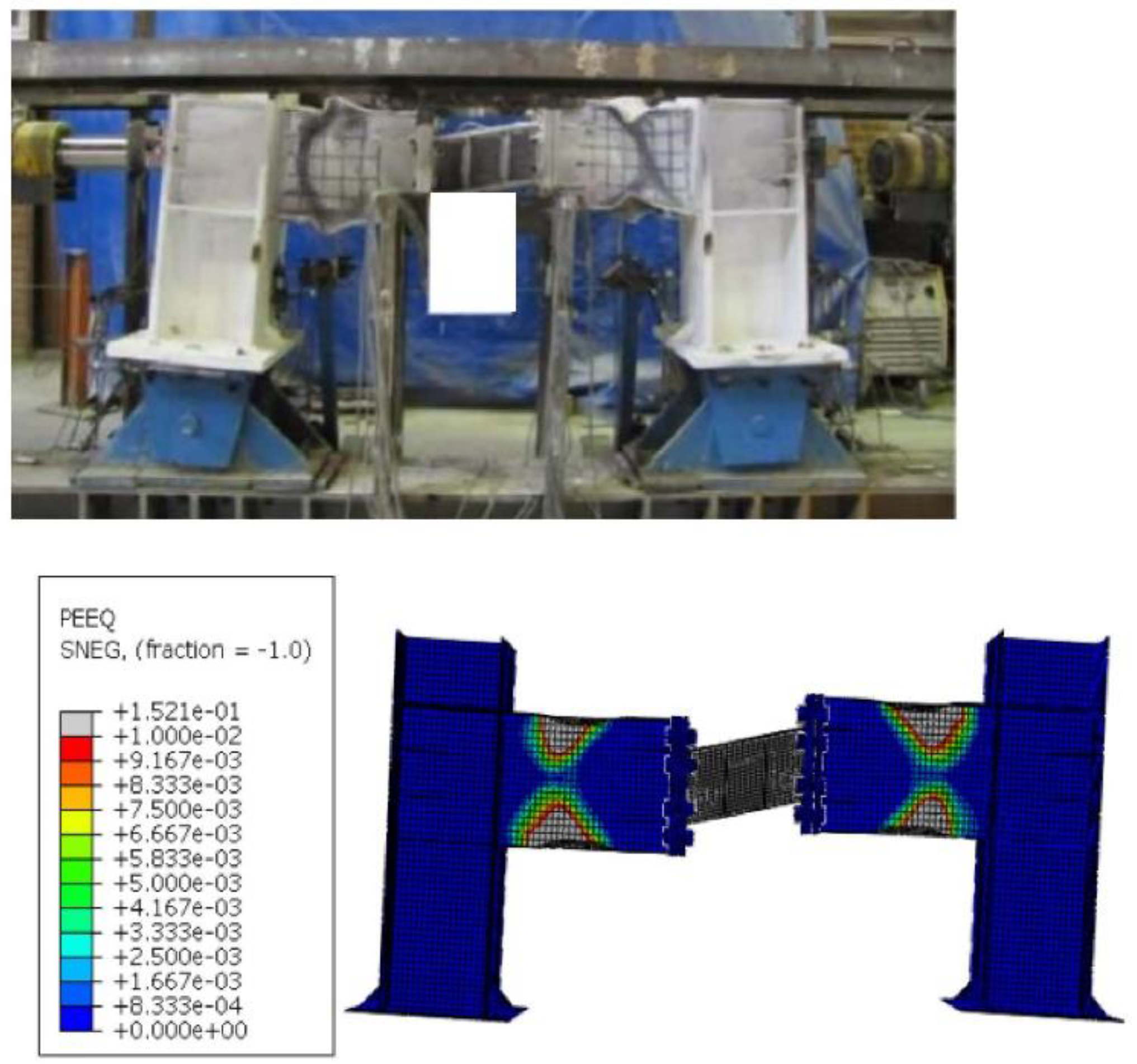
2. Finite Element Test Verification
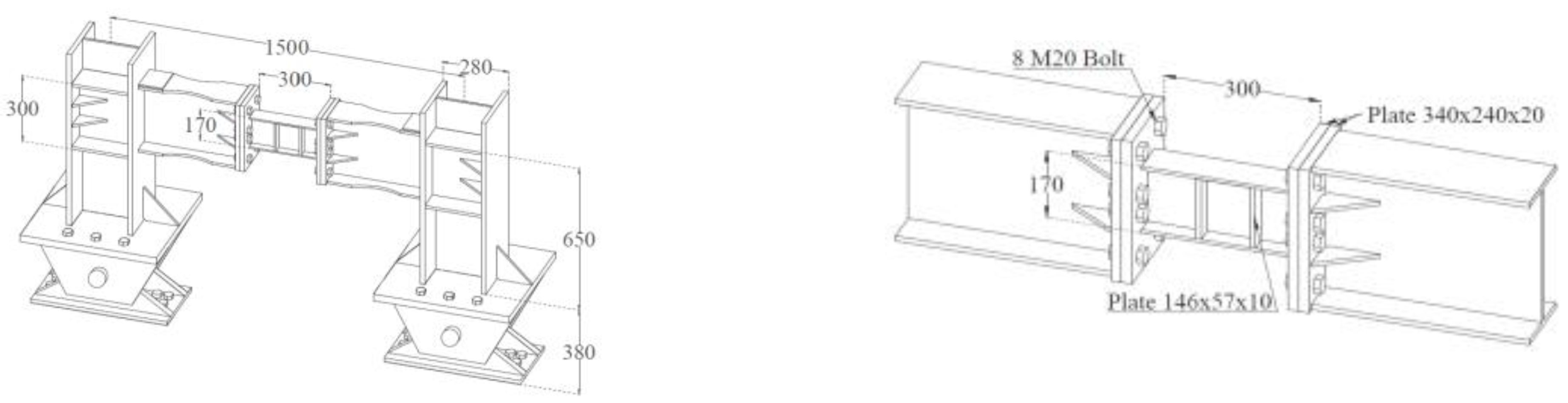
2.1. Test of Replaceable Link
2.1.1. Test Overview
2.1.2. Test Model
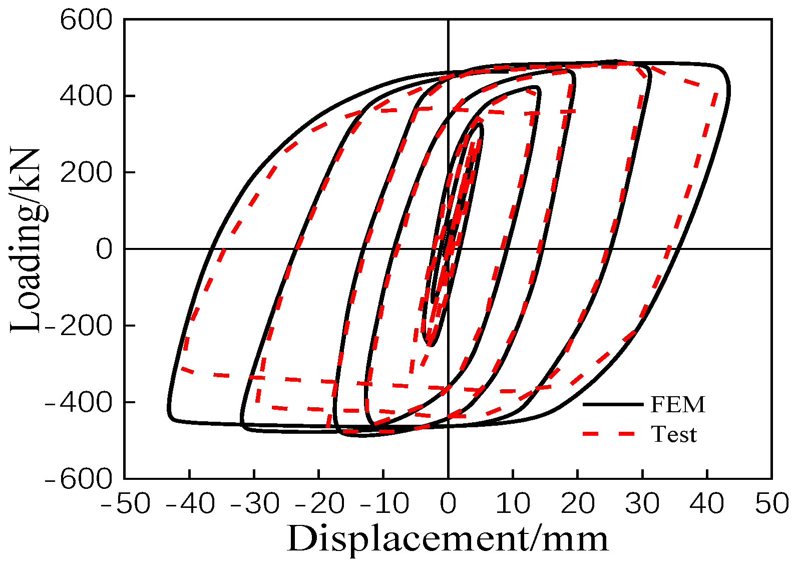
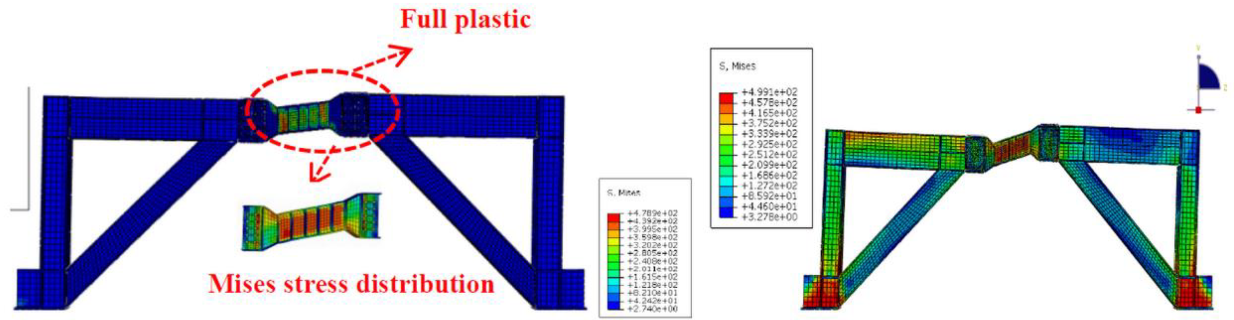
2.1.3. FEM Results
2.2. K-Typed Eccentrically Braced Steel Frame Test
2.2.1. Overview
2.2.2. Experimental Model
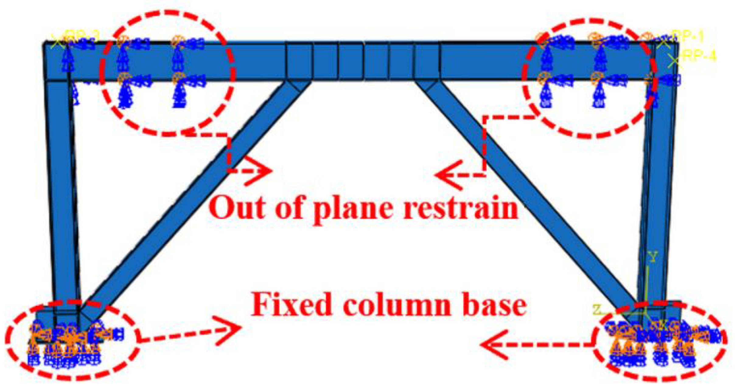
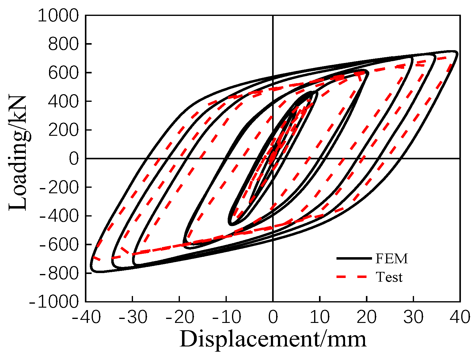
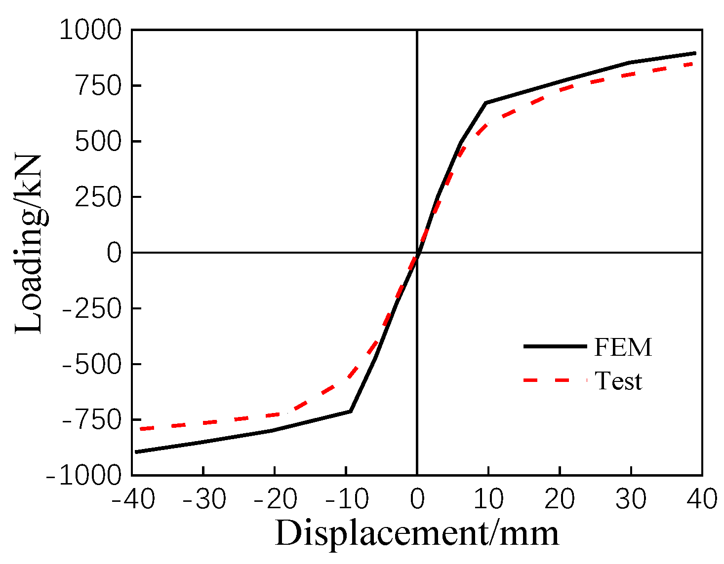
2.2.3. FEM Results
3. Base Model Design
4. Discussion Results for the Base Model
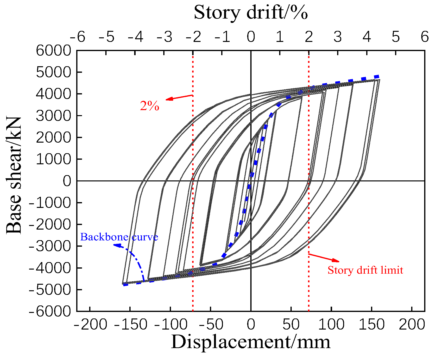
4.1. Hysteresis Performance
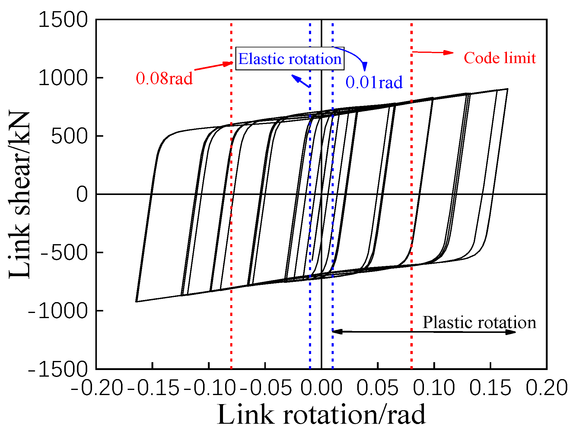
4.2. Plastic Rotation
5. Finite Element Parametric Analysis
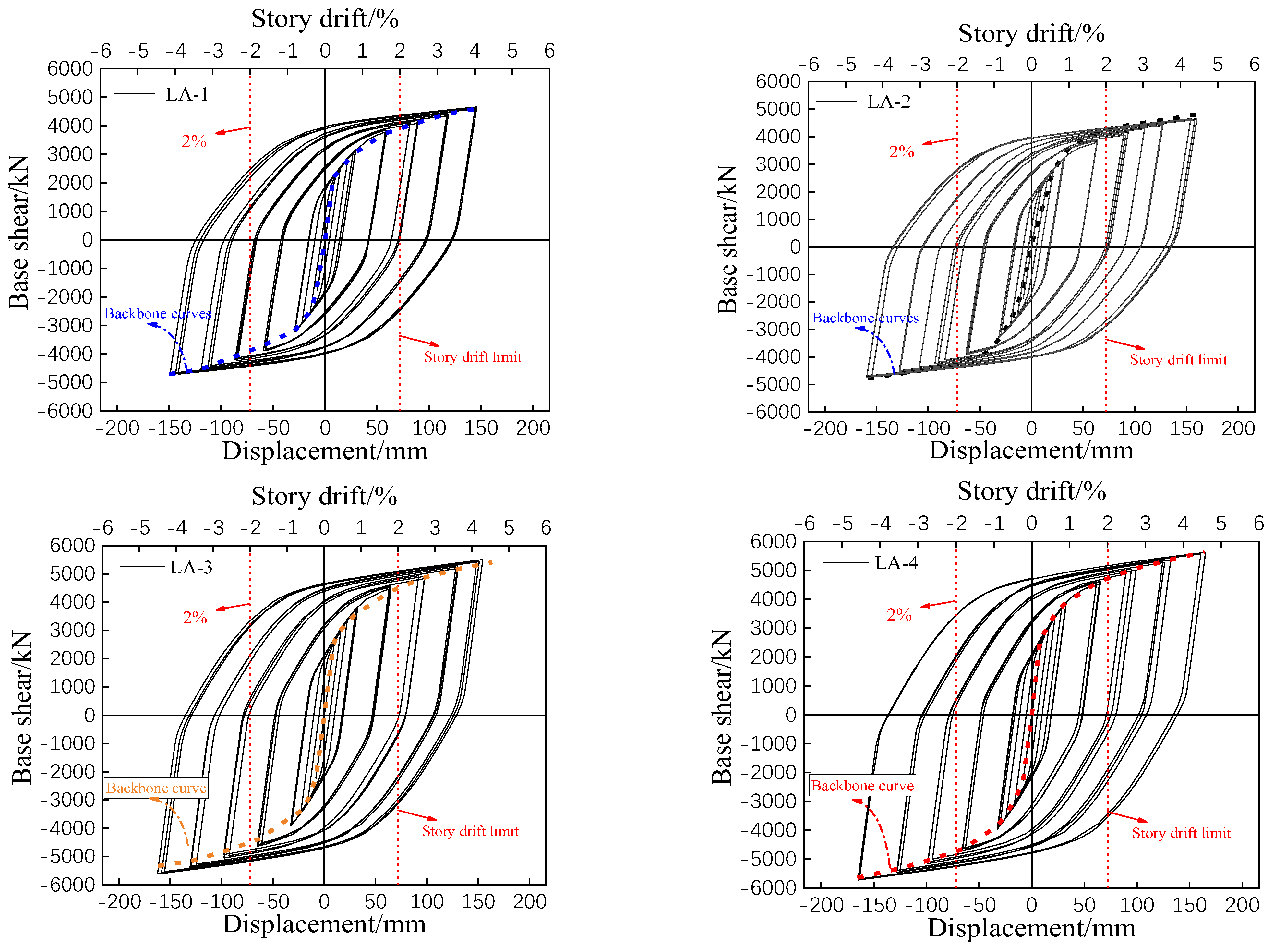
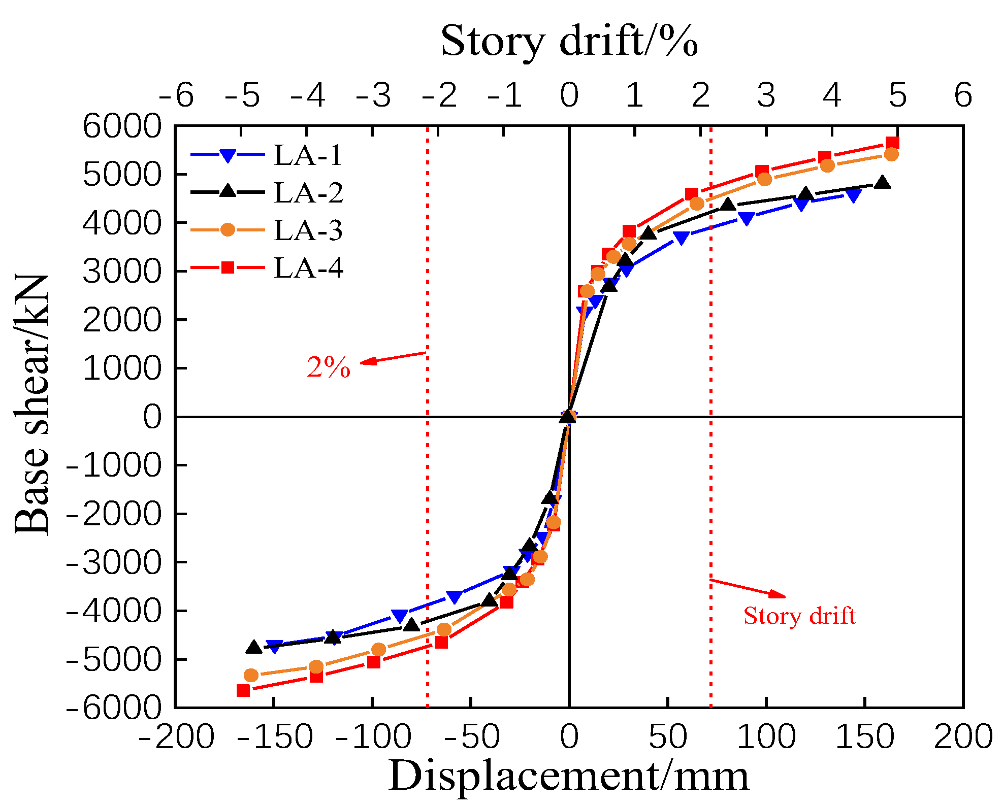
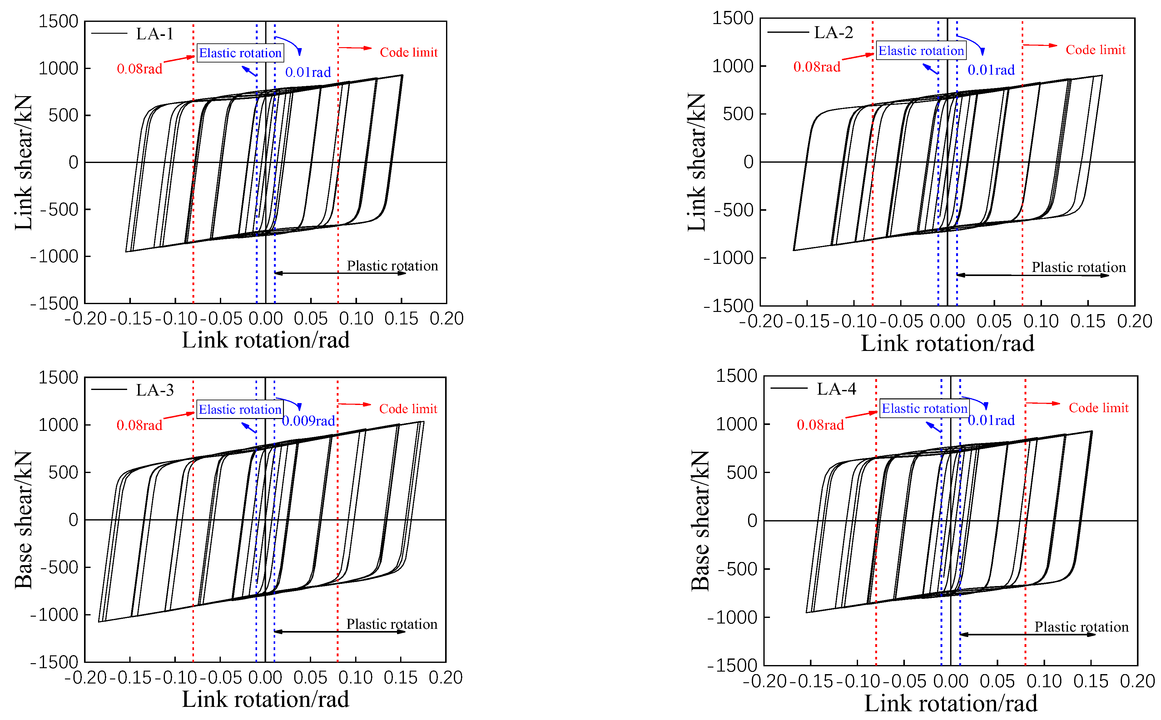
5.1. Analysis of LA Series Results
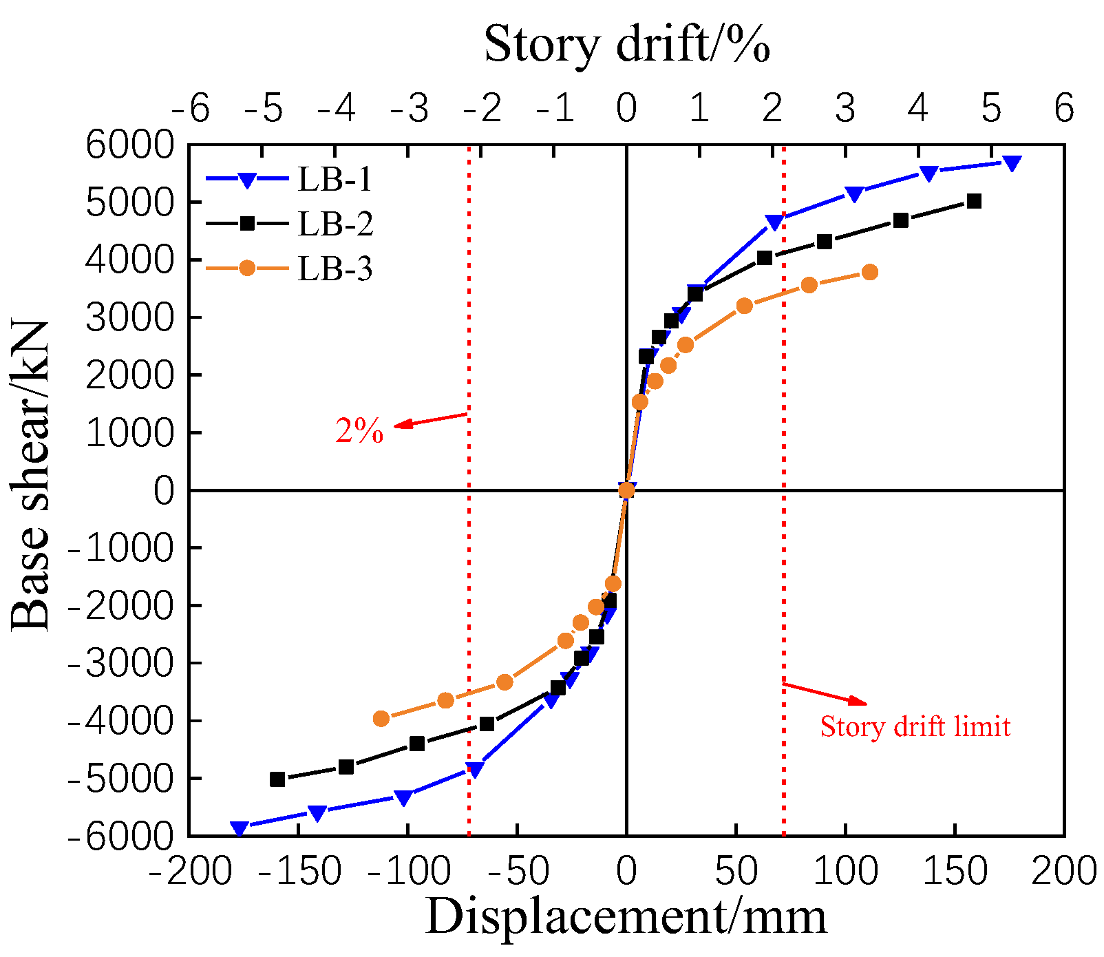
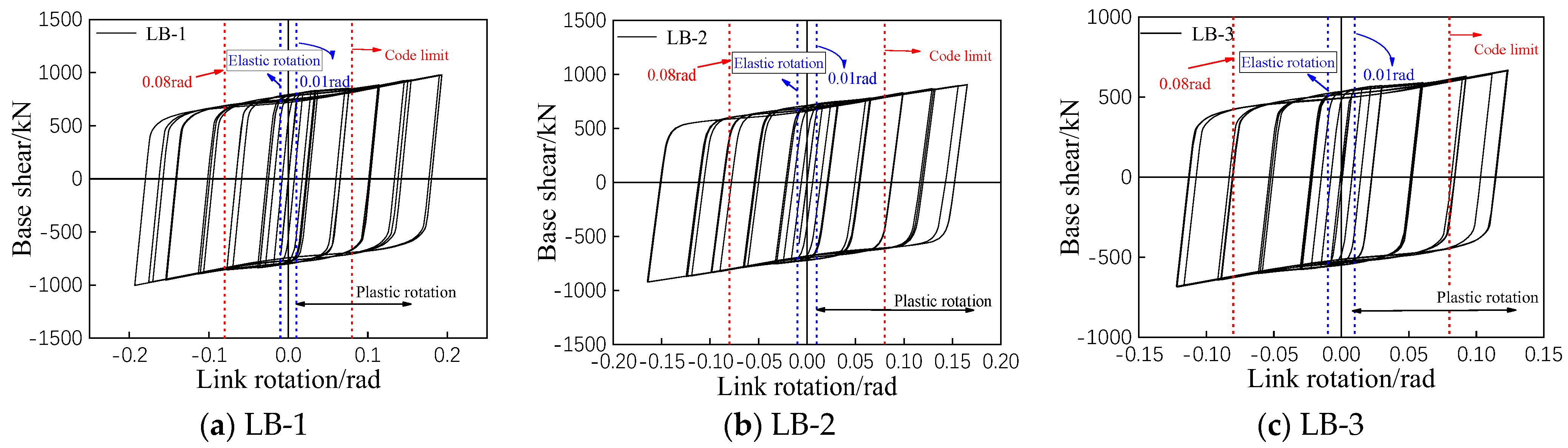
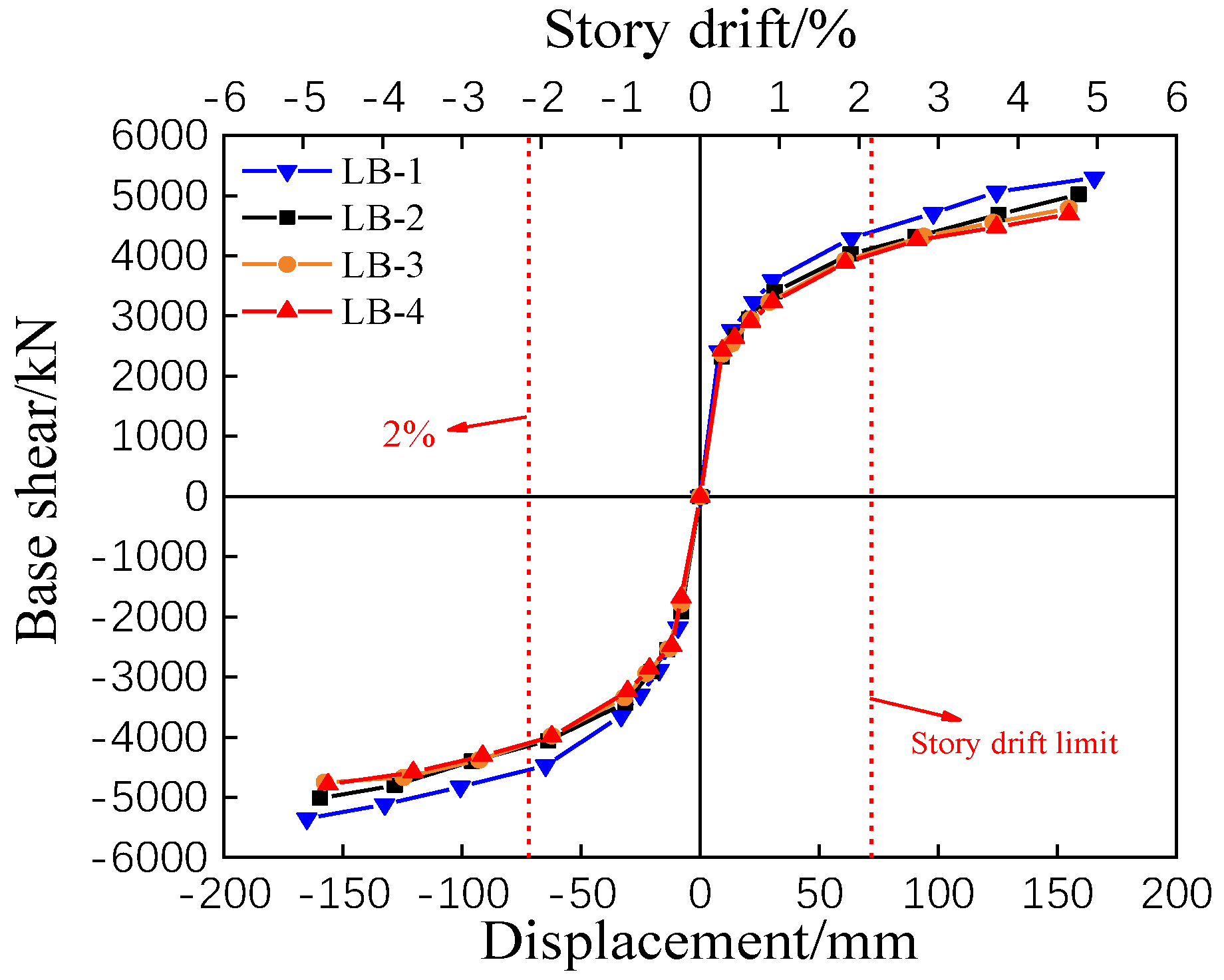
5.2. Analysis of LB Series
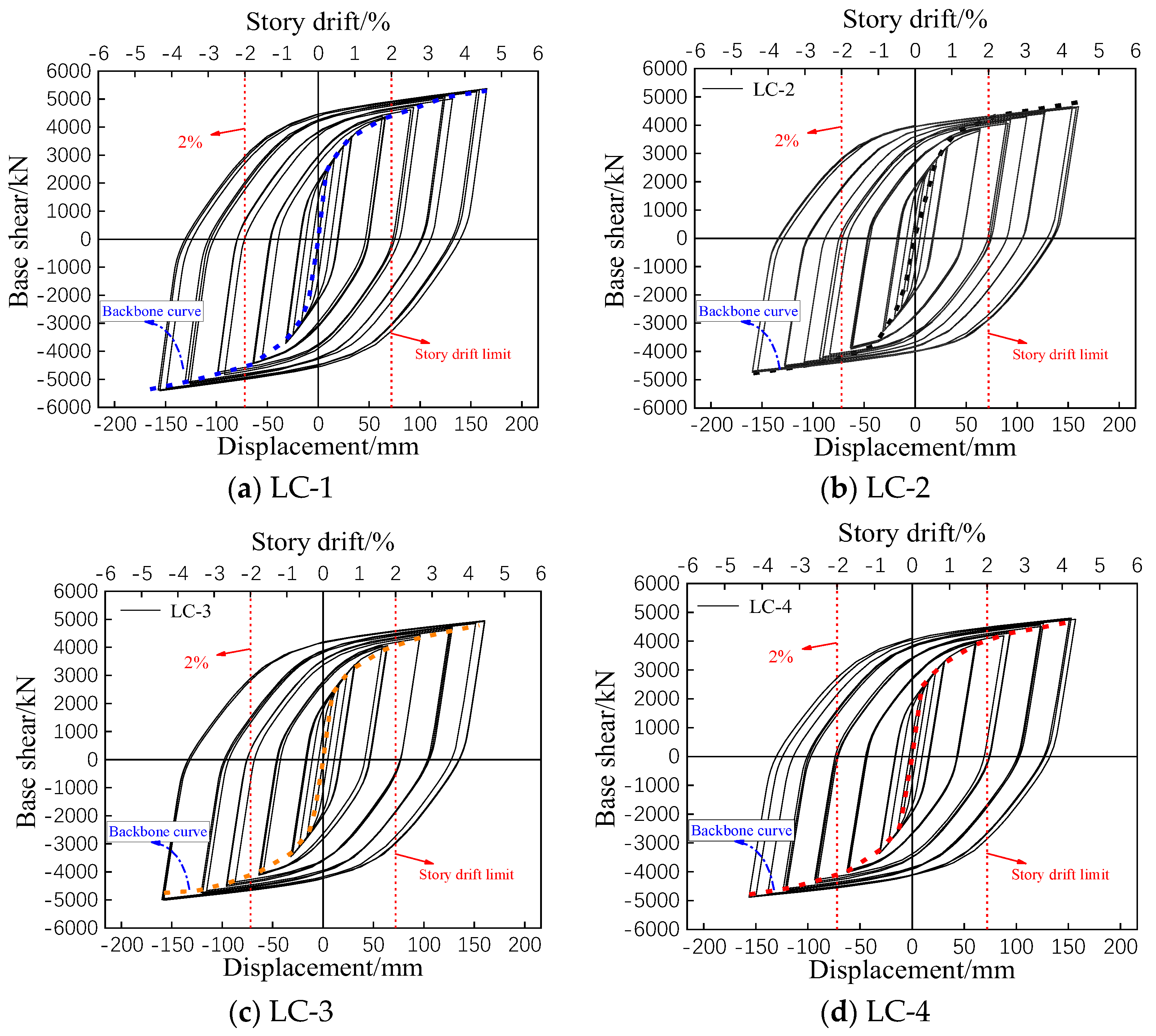
5.3. Analysis of LC Series Finite Element Result
6. Conclusions
- (1)
- Regarding the replaceable link causing shear-yielding, reducing the length of the energy-consuming region will clearly improve the loading capacity, ductility, and rotational performance of replaceable link, but neither will enhance the stiffness of the structure. The replaceable link should be limited to (0.92–1.17) Mp/Vp when designing high-strength eccentrically braced steel frame structures with the replaceable link; excessively long energy-consuming regions will not provide better performance.
- (2)
- The steel strength of the link and other components presents a significant impact on the mechanical and seismic properties of the structure. Under cyclic loading, with the increasing strength of steel, the ductility coefficient of the structure decreases while the loading capacity of the structure and the rotation of the replaceable link significantly improve; meanwhile, the initial stiffness of various structures is not obvious to the strength of steel. This suggests the application of Q690 for the frame, while Q345 for the replaceable link can present the best seismic performance of the structure.
- (3)
- The length of the replaceable link also presents a significant impact on the seismic performance of the structure. The reduction in length will clearly improve the loading capacity, ductility, the plastic rotation of the replaceable link, and the energy dissipation capacity of the structure. Especially, reducing the length of the replaceable link can lead to the increase in the initial stiffness and the decrease in stiffness degradation of the structure. The initial stiffness, bearing capacity, and ductility factor are decreased about 6%, 2.3%~4.9%, and 6%~7%, respectively, when the length of the link increases by 100 mm.
Author Contributions
Funding
Acknowledgments
Conflicts of Interest
References
- Oliveira, J.P.; Panton, B.; Zeng, Z.; Omori, T.; Zhou, Y.; Miranda, R.M.; Fernandes, F.B. Laser welded superelastic Cu–Al–Mn shape memory alloy wires. Mater. Des. 2016, 90, 122–128. [Google Scholar] [CrossRef]
- Oliveira, J.P.; Zeng, Z.; Omori, T.; Zhou, N.; Miranda, R.M.; Fernandes, F.M.B. Improvement of damping properties in laser processed superelastic Cu-Al-Mn shape memory alloys. Mater. Des. 2016, 98, 280–284. [Google Scholar] [CrossRef]
- Azad, S.K.; Topkaya, C. A review of research on steel eccentrically braced frames. J. Constr. Steel Res. 2017, 128, 53–73. [Google Scholar] [CrossRef]
- Li, S.; Tian, J.; Liu, Y. Performance-based seismic design of eccentrically braced steel frames using target drift and failure mode. Earthq. Struct. 2017, 13, 443–454. [Google Scholar]
- Li, S.; Wang, C.; Li, X.; Jian, Z.; Tian, J.B. Seismic behavior of K-type eccentrically braced frames with high strength steel based on PBSD method. Earthq. Struct. 2018, 15, 667–685. [Google Scholar]
- Dubina, D.; Stratan, A.; Dinu, F. Dual high-strength steel eccentrically braced frames with removable links. Earthq. Eng. Struct. Dyn. 2010, 37, 1703–1720. [Google Scholar] [CrossRef]
- Dubina, D.; Stratan, A.; Vulcu, C.; Ciutina, A. High strength steel in seismic resistant building frames. Steel Constr. 2015, 7, 173–177. [Google Scholar] [CrossRef]
- Cheng, Q.; Lian, M.; Su, M.; Zhang, H. Experimental and finite element study of high-strength steel framed-tube structures with replaceable shear links under cyclic loading. Structures 2021, 29, 45–64. [Google Scholar] [CrossRef]
- Lian, M.; Cheng, Q.; Guan, B.; Zhang, H.; Su, M. Seismic performance of high-strength steel framed-tube structures with bolted web-connected replaceable shear links. Steel Compos. Struct. 2020, 37, 323–339. [Google Scholar]
- Zhang, H.; Su, M.; Lian, M.; Cheng, Q.; Guan, B.; Gong, H. Experimental and numerical study on the seismic behavior of high-strength steel framed-tube structures with end-plate-connected replaceable shear links. Eng. Struct. 2020, 223, 111172. [Google Scholar] [CrossRef]
- Cheng, Q.; Su, M.; Lian, M.; Zhang, H.; Guan, B.; Gong, H. Cyclic behavior of high-strength steel framed-tube structures with bolted replaceable shear links. Eng. Struct. 2020, 210, 110395. [Google Scholar] [CrossRef]
- Guan, B.; Su, M.; Lian, M. Seismic behaviour of combined steel framed-tube substructure with replaceable shear links. J. Constr. Steel Res. 2020, 167, 105968. [Google Scholar] [CrossRef]
- Lian, M.; Zhang, H.; Cheng, Q.; Su, M. Finite element analysis for the seismic performance of steel frame-tube structures with replaceable shear links. Steel Compos. Struct. 2019, 30, 365–382. [Google Scholar]
- Lian, M.; Su, M.Z.; Guo, Y. Seismic performance of eccentrically braced frames with high strength steel combination. Steel Compos. Struct. 2015, 18, 1517–1527. [Google Scholar] [CrossRef]
- Lian, M.; Su, M.Z. Seismic performance of high-strength steel fabricated eccentrically braced frame with vertical shear link. J. Constr. Steel Res. 2017, 137, 262–285. [Google Scholar] [CrossRef]
- Lian, M.; Su, M.Z. Experimental study and simplified analysis of EBF fabricated with high strength steel. J. Constr. Steel Res. 2017, 139, 6–17. [Google Scholar] [CrossRef]
- Lian, M.; Su, M.Z.; Guo, Y. Experimental performance of Y-shaped eccentrically braced frames fabricated with high strength steel. Steel Compos. Struct. 2017, 24, 441–453. [Google Scholar]
- Nikoukalam, M.T.; Dolatshahi, K.M. Development of structural shear fuse in moment resisting frames. J. Constr. Steel Res. 2015, 114, 349–361. [Google Scholar] [CrossRef]
- AISC341-10; Seismic Provision for Structure Steel Buildings. American Institute of Steel Construction: Chicago, IL, USA, 2010.
- Li, S.; Wang, Z.Y.; Guo, H.C.; Li, X.L. Seismic performance of high strength steel frames with variable eccentric braces based on PBSD method. Earthq. Struct. 2020, 18, 527–542. [Google Scholar]
- GB50011-2010; Code for Seismic Design of Buildings. China Architecture Industry Press: Beijing, China, 2016. (In Chinese)


| Steel Grade | t/mm | fy/MPa | fu/MPa | E/(×105/MPa) | Elongation/% |
|---|---|---|---|---|---|
| Q345B | 6 | 427.40 | 571.10 | 2.01 | 26.53 |
| Q345B | 10 | 383.33 | 554.40 | 2.00 | 31.01 |
| Q460C | 6 | 496.90 | 658.57 | 2.08 | 29.73 |
| Q460C | 10 | 468.77 | 627.97 | 2.02 | 35.88 |
| Specimen | Cross-Section | Length/(mm) | H-Shaped Section |
|---|---|---|---|
| Beam | H620 × 180 × 10 × 16 | 2480 |  |
| Column | H400 × 400 × 12 × 12 | 3600 | |
| Brace | H260 × 180 × 10 × 16 | 4275 | |
| Energy consuming region | H500 × 180 × 10 × 16 | 840 (e) | |
| link | H620 × 180 × 10 × 16 | 1840 (e’) |
| LA Series | Number | LA-1 | LA-2 | LA-3 | LA-4 |
| e/mm | 924 | 840 | 756 | 672 | |
| ρ | 1.28 | 1.17 | 1.04 | 0.92 | |
| Steel | Q345/Q460 | Q345/Q460 | Q345/Q460 | Q345/Q460 | |
| LB Series | Number | LB-1 | LB-2 | LB-3 | \ |
| Steel | Q345/Q690 | Q345/Q460 | Q235/Q460 | \ | |
| e/mm | 840 | 840 | 840 | \ | |
| ρ | 1.17 | 1.17 | 1.17 | \ | |
| LC Series | Number | LC-1 | LC-2 | LC-3 | LC-4 |
| e/mm | 840 | 840 | 840 | 840 | |
| e’ | 1740 | 1840 | 1940 | 2040 | |
| ρ | 1.17 | 1.17 | 1.17 | 1.17 |
| Model Number | Yielding Displacement (mm) | Yielding Loading (kN) | Ultimate Displacement (mm) | Ultimate Loading (kN) | Initial Stiffness (kN/mm) | Ductility μ |
|---|---|---|---|---|---|---|
| LA-1 | 29.8 | 3560.6 | 157.6 | 4782.3 | 258.5 | 5.29 |
| LA-2 (Base) | 32.4 | 3720.4 | 170.5 | 4983.5 | 261.8 | 5.26 |
| LA-3 | 32.7 | 3796.5 | 180.5 | 5106.8 | 274.2 | 5.52 |
| LA-4 | 33.1 | 3890.4 | 189.7 | 5219.5 | 275.7 | 5.73 |
| LB-1 | 35.6 | 4289.5 | 218.1 | 6151.1 | 260.3 | 6.13 |
| LB-2 (Base) | 32.4 | 3720.4 | 170.5 | 4983.5 | 261.8 | 5.26 |
| LB-3 | 28.4 | 2995.3 | 134.5 | 4135.7 | 259.7 | 4.73 |
| LC-1 | 33.2 | 3752.2 | 184.1 | 5240.2 | 277.9 | 5.55 |
| LC-2 (Base) | 32.4 | 3720.4 | 170.5 | 4983.5 | 261.8 | 5.26 |
| LC-3 | 32.1 | 3635.8 | 164.8 | 4870.8 | 245.1 | 5.13 |
| LC-4 | 31.5 | 3485.7 | 150.1 | 4792.7 | 230.6 | 4.77 |
Publisher’s Note: MDPI stays neutral with regard to jurisdictional claims in published maps and institutional affiliations. |
© 2022 by the authors. Licensee MDPI, Basel, Switzerland. This article is an open access article distributed under the terms and conditions of the Creative Commons Attribution (CC BY) license (https://creativecommons.org/licenses/by/4.0/).
Share and Cite
Li, X.; Fan, B.; Li, S.; Liang, G.; Xi, H. Finite Element Parametric Analysis of High-Strength Eccentrically Braced Steel Frame with Variable-Cross-Section Replaceable Link. Appl. Sci. 2022, 12, 9447. https://doi.org/10.3390/app12199447
Li X, Fan B, Li S, Liang G, Xi H. Finite Element Parametric Analysis of High-Strength Eccentrically Braced Steel Frame with Variable-Cross-Section Replaceable Link. Applied Sciences. 2022; 12(19):9447. https://doi.org/10.3390/app12199447
Chicago/Turabian StyleLi, Xiaolei, Bin Fan, Shen Li, Gang Liang, and Hong Xi. 2022. "Finite Element Parametric Analysis of High-Strength Eccentrically Braced Steel Frame with Variable-Cross-Section Replaceable Link" Applied Sciences 12, no. 19: 9447. https://doi.org/10.3390/app12199447
APA StyleLi, X., Fan, B., Li, S., Liang, G., & Xi, H. (2022). Finite Element Parametric Analysis of High-Strength Eccentrically Braced Steel Frame with Variable-Cross-Section Replaceable Link. Applied Sciences, 12(19), 9447. https://doi.org/10.3390/app12199447