Abstract
Large-scale tanks are widely used for storing chemicals and fuels. Their failure due to natural (e.g., earthquakes) and/or man-made hazards can lead to disastrous consequences. Nonetheless, they are often constructed in seismic-prone regions. For this reason, base isolation is often used for the seismic protection of large tanks, aiming to “decouple” the superstructure from the imposed ground motions. In this study, a combined optimization formulation is presented in order to further improve the seismic response of a base-isolated tank. The main aim is to optimize both the critical design parameters and the placement of the minimum number of isolators at the base of the tank. In particular, a Cuckoo Search (CS) optimizer is used to optimize the dynamic performance of liquid storage tanks, isolated either via single friction pendulum bearings (SFPB) or triple friction pendulum bearings (TFPB). The main objective is to minimize the eccentricity between the center of mass and the center of rigidity of the isolation system, while appropriate constraints are also imposed. Several cases are examined, while the results are compared with respect to isolator displacement fragility curves, as well as the reduced accelerations at the base of the tank. According to the findings of this study, the tank industry can significantly benefit from the proposed approach, as a more cost-efficient design of the base-isolation system of large-scale tanks can be achieved, i.e., using fewer isolators with optimal key parameters.
1. Introduction
Water, fuels and chemicals are usually stored in large-scale tanks, which are often constructed in seismic-prone regions. In past earthquakes (e.g., Northridge 1994; Kobe 1995; etc.), leakages and explosions were observed. In general, the main earthquake-related damages of liquid storage tanks are the following: (a) the “elephant-foot” buckling, (b) the “diamond-shape” buckling and (c) roof damage due to excessive liquid sloshing. Undoubtedly, such critical infrastructure should remain safe and functional even after a severe seismic event. Nonetheless, they behave quite differently to conventional structures (e.g., buildings, bridges, etc.) during an earthquake, due to the hydrodynamic interaction of their walls with their liquid content.
Housner [1] developed a mechanical analogue to simulate the hydrodynamic response of the liquid-tank system by decoupling it from two components: (i) the lower part of the liquid content that moves together with the tank walls, the so-called impulsive component, and (ii) the upper part of the liquid content that moves independently and causes sloshing, i.e., the convective component. Subsequent studies (by Veletsos et al. [2]; Malhotra [3]; among others) have proven that the global tank response is mainly governed by the impulsive component of the liquid content. Consequently, the convective component can be neglected, as it is related to high periods (e.g., >6 s for the examined tank in the present investigation), that are considerably higher compared to the fundamental period of the tank-liquid system (e.g., ≈1.5 s for the examined isolated tank, while it is <0.2 s for the same tank for fixed-base conditions).
In order to diminish the potential detrimental effects of the ground motions on large and/or important structures and non-structural elements (e.g., statues, sensitive equipment, etc.), several base-isolation schemes have been frequently applied in engineering practice [4]. The main goal of all base-isolation schemes is to “decouple” the response of the superstructure from the imposed ground shaking via suitable devices with low horizontal and high vertical stiffness, which is necessary in order to carry the structural weight. In this manner, the dynamic distress of the tank is considerably reduced, while the displacements are increased due to the increased flexibility of the isolators. Such base-isolated tanks with quite large dimensions have been constructed in many countries.
Many researchers have applied various optimization formulations and techniques to design isolators that exhibit an optimal dynamic performance. Several studies have investigated the performance of frictional bearings utilizing an optimization formulation. Jangid [5] presented the optimization of friction coefficient of a sliding system to minimize the accelerations of a base-isolated structure under seismic excitations. It was reported that the damping ratios and the periods of the isolation system and the structure, the ratio of base to superstructure masses, as well as the frequency content and the intensity of seismic excitations had a significant impact on the results. Subsequently, Jangid [6] investigated the behavior of buildings isolated via single friction pendulum bearings (SFPB) under near-fault excitations. The objective was the minimization of sliding displacements and top accelerations, while the resulting optimal coefficient of friction values were between 0.05 to 0.15.
Bucher [7] improved the performance of friction-based isolators by developing a Pareto-type optimization formulation with conflicting objective functions. It was found that the optimized design parameters are taken from a relatively narrow range of values. A non-dominated sorting genetic algorithm (NSGA-II) was applied by Calafell et al. [8] to perform optimization on SFPB isolators installed at a masonry house in Chile. It was found that SFPB isolators reduced the superstructure demands. Charmpis et al. [9] investigated the optimal vertical placement of isolators in multi-story buildings. The aim of the optimization was the minimization of the maximum floor accelerations, while the constraints were related to interstory drifts, maximum base displacements and the seismic isolation total cost.
Chung et al. [10] obtained the optimal friction coefficient by minimizing the sum of squares of structural absolute accelerations. The results revealed that the optimization of friction coefficient depended more on the isolation period than on various other ratios (mass, damping, etc.). The optimization of isolators parameters installed at multi-story buildings via harmony search (HS) was examined by Nigdeli et al. [11]. It was shown that the HS algorithm was an efficient optimization technique considering this application, and it proved its robustness regarding the variation in the ground motion characteristics. Moeindarbari and Taghkikhany [12] implemented genetic algorithms (GA) to perform optimization of structures isolated with triple friction pendulum bearings (TFPB) under three seismic hazard levels. It was concluded that the outer (i.e., upper and lower) concave sliding surface parameters (curvature radii, friction coefficients, displacement capacities) of TFPB isolators had a more significant effect on the structural response compared to the inner sliding surface properties, while the hazard level had a marginal influence on the optimization results.
Das et al. [13] examined the optimal performance of a base-isolated building considering the limitation on excessive isolator displacements. It was shown that the constrained-optimal isolation system produced significantly different results compared to the unconstrained formulation. Castaldo and Ripani [14] studied the impact of foundation layer characteristics on the dynamic response of buildings isolated with SFPB. Taking into account soil–structure interaction, the optimum SFPB parameters were derived from a wide range of friction bearing properties. Zou et al. [15] presented a performance-based optimization formulation for multi-story buildings isolated with multiple-coupling friction dampers. The performance parameters of the isolation scheme were used as design variables, the displacements and accelerations were chosen as the objectives and the optimization problem was solved via sequential quadratic programming.
Recently, Tsipianitis and Tsompanakis [16] presented a study on sizing optimization of SFPB and TFPB isolators placed at the base of liquid storage tanks, using several nature-inspired optimizers. The minimization of tank base accelerations was the objective of this formulation, while the constraints were related to the vibration period and damping capacity of the isolators. Çerçevik et al. [17] implemented three bio-inspired search methods in order to achieve the optimization of the isolation period and damping ratio of a simple four-story, two-dimensional frame isolated with rubber bearings. The results were compared with those obtained via HS optimizer by Nigdeli et al. [11], while it was reported that the three algorithms converged to similar optimum values. A limited number of far- and near-fault accelerograms were used, and it was found that near-fault records are the most influential ones, resulting in less favorable seismic response parameters during the optimization process.
The impact of three control systems, namely tuned viscous mass damper (TVMD), tuned inerter damper (TID) and tuned mass damper (TMD), on improving the seismic response of base isolated structures was compared by Li et al. [18]. Suitable optimization formulations were applied to optimize the properties of the three control systems. According to the results of this study, all three optimal control systems effectively reduced the dynamic distress of the isolated structure. Ocak et al. [19] applied an adaptive harmony search algorithm to optimize the base isolation system of a structure. Regarding the optimization formulation, the emphasis was placed on determining the optimal parameters of the isolation period and damping ratio, while the objective function was related to the minimization of superstructure acceleration. The results show that the total acceleration of the structure was reduced when the isolator’s ductility was increased.
In most relevant studies, the optimization of the seismic performance of the isolation system was mainly focused on isolators’ critical parameters, such as the friction coefficient, radius of curvature, etc. A literature review revealed that there is no relevant study that has focused on the combined optimization of both the key parameters (i.e., sizing optimization) and the layout (i.e., optimal placement) of the isolators installed at the base of buildings or tanks. For this reason, single and dual optimization of liquid storage tanks, isolated either by SFPB or TFPB, is investigated herein. The computationally efficient nature-inspired Cuckoo Search (CS) algorithm is used for the solution of the optimization problems. The optimized configurations are assessed by comparing the fragility curves with respect to isolators’ maximum displacements when the coupled system (isolators and superstructure) is subjected to near-fault excitations utilizing an incremental dynamic analysis process. A base-isolated tank with SFPB or TFPB isolators with identical properties derived from a standard design approach is used as the reference case for comparison with the optimized designs. In the first optimization formulation, the number of isolators is kept constant and the key parameters (friction coefficients and radii of curvature) of the bearings are optimized. In the dual formulation, the optimization includes both the sizing parameters in conjunction with the optimal placement of the isolators at the tank base, eliminating redundant ones. It is proven that the proposed combined approach leads to a more cost-efficient design, with fewer isolators compared to the conventional design.
2. Examined Friction Bearings
2.1. Single Friction Pendulum Bearings
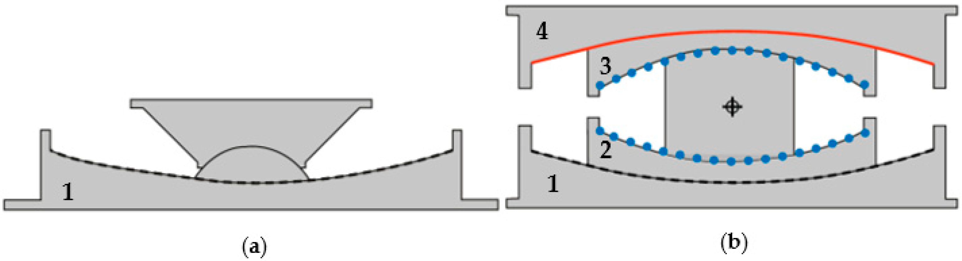
Single friction pendulum bearings (SFPB) are efficient isolation devices for the seismic protection of buildings, bridges and tanks, while they can be also used as a retrofit technique for existing structures [20]. These bearings have an axisymmetric shape and take advantage of their spherical geometry to provide seismic isolation [21]. Figure 1a presents a typical SFPB configuration, while it can also be installed with the spherical surface facing down. The spherical bearing surface with steel–teflon type interface represents a pendulum motion, while the period of the isolator is determined by the radius of curvature of this concave sliding surface. A characteristic feature of SFPB is that the center of stiffness (i.e., rigidity) coincides with the center of mass. In this manner, the torsional distress of the superstructure is minimized. Accordingly, the structural response, ductility and energy dissipation can be efficiently controlled, while damages to structural components—as well as to non-structural elements and contents in buildings—are minimized even for severe seismic events.

Figure 1.
Section view of: (a) SFPB and (b) TFPB (Reprinted from Computers and Structures, Volume 243, Alexandros Tsipianitis and Yiannis Tsompanakis, Optimizing the seismic response of base-isolated liquid storage tanks using swarm intelligence algorithms, Pages No. 106407,Copyright (2022), with permission from Elsevier.
2.2. Triple Friction Pendulum Bearings
More recently, multi-stage friction isolators, such as triple friction pendulum bearings (TFPB), have been implemented in engineering practice. A TFPB is a sliding isolation device with adaptive characteristics, which can exhibit different stiffness, strength and damping properties depending on the circumstances. A TFPB has multiple spherical concave sliding surfaces, which enable the transmission of lower vibrations to the superstructure, while maintaining zero residual displacements at the bearings.
Consequently, its operation is quite different compared to the single sliding bearings (i.e., SFPB), which exhibit constant stiffness and energy dissipation. In other words, the various potential combinations of the curvature and friction coefficient of the sliding surfaces, which can be adjusted according to the imposed seismic levels, increase the flexibility and effectiveness of TFPB. In this manner, several performance objectives can be attained, and this is ideal from a performance-based design (PBD) perspective (Figure 1b). More details regarding the successful implementation of TFPB in liquid storage tanks can be found in [22].
3. SFPB and TFPB Fragility Function Evaluation
In general, seismic fragility is associated with the probability of exceedance of a limit state for a given seismic intensity level. Peak ground acceleration (PGA) has been adopted as a suitable intensity measure (IM) for liquid storage tanks in several relevant studies. For instance, PGA was used by Salzano et al. [23] for the seismic risk assessment for atmospheric tanks, based on the recommendations of ALA [24]. Bakalis et al. [25] also reported that PGA can be used to interpret the dynamic response of tanks due to the impulsive load pattern of the liquid content. Moreover, Saha et al. [26] stated that PGA is ideal when assessing the seismic fragility of base-isolated tanks, as it is associated with peak response quantities.
In the present work, fragility curves for both SFPB and TFPB for standard and for optimized main parameters are evaluated for the Maximum Credible Earthquake (MCE) with 2% probability of exceedance in 50 years (as shown in Figure 2). The methodology presented by Baker [27] has been adopted for the fragility analysis, in which a lognormal cumulative distribution function correlates the failure probabilities (i.e., in terms of isolator displacement capacity exceedance) with the selected IM. In this manner, the fragility curves can be derived via multiple dynamic analyses utilizing the selected accelerograms and various PGA levels.

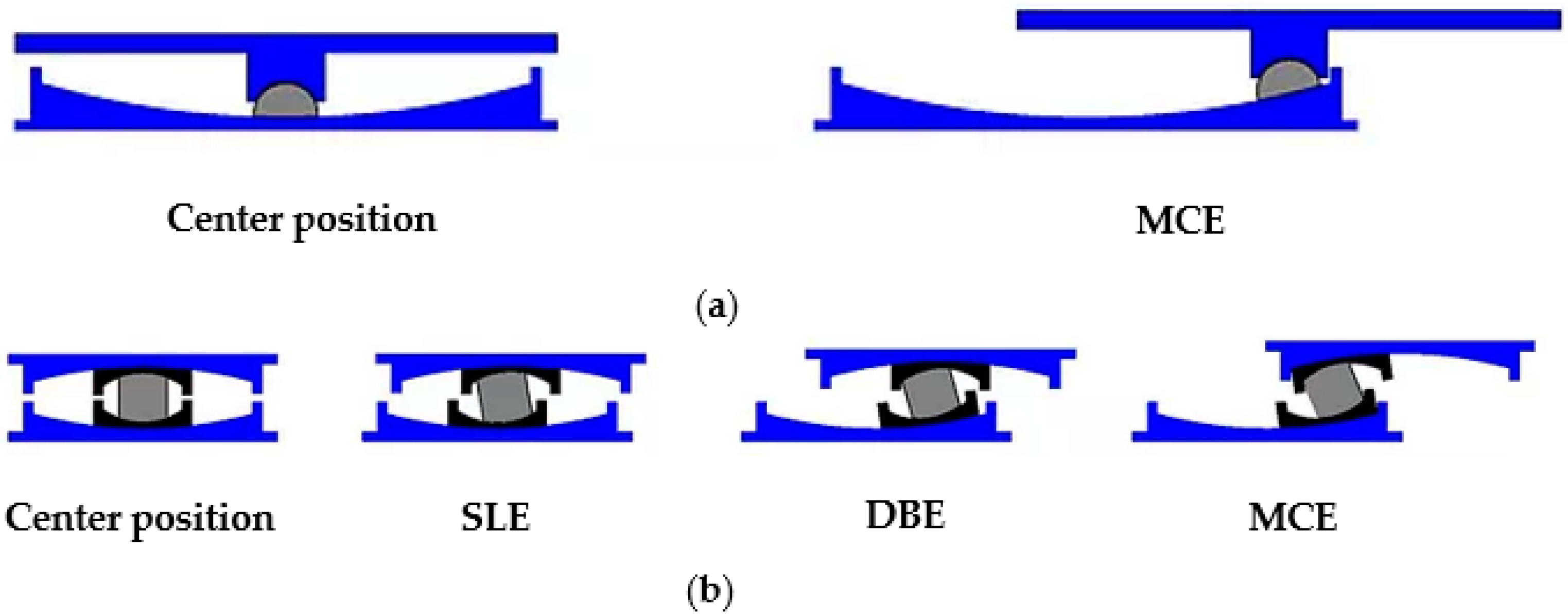
Figure 2.
Performance levels for static conditions (left sketches) and various seismic scenarios (SLE = Service Level Earthquake, DBE = Design Basis Earthquake and MCE = Maximum Credible Earthquake) for: (a) SFPB and (b) TFPB (Reprinted from Computers and Structures, Volume 243, Alexandros Tsipianitis and Yiannis Tsompanakis, Optimizing the seismic response of base-isolated liquid storage tanks using swarm intelligence algorithms, Pages No. 106407, Copyright (2022), with permission from Elsevier).
4. Base-Isolated Liquid Storage Tank
4.1. Case Study Models and Design Parameters
In the present investigation, the tank model “Tank B”, initially presented by Haroun [28] is used, which is a squat cylindrical tank with height-to-radius ratio H/R = 0.67. The thickness of tank wall is t = 0.0254 m, the radius is R = 18.29 m, the height of the liquid is H = 12.19 m, while the weight of the content is W = 126.27 MN. The fundamental period of the fixed-base tank-liquid system is Tf-B = 0.162 s. It is noted that a slender storage tank has not been included in this investigation, since the fragility curves of isolator displacements are marginally affected by the geometry of the base-isolated tanks [22].
4.2. Surrogate Tank Model
Numerical simulation of tanks is a difficult task due to the complexity of liquid-tank hydrodynamic behavior [29], since the explicit simulation of the liquid content results in computationally demanding models. In order to achieve an optimal balance among computational cost, model complexity and accuracy, valid surrogate models are frequently developed instead of complicated three-dimensional (3D) models. Konstandakopoulou and Hatzigeorgiou [30] stated that simulating liquid storage tanks as mechanical analogs is suggested in contemporary seismic norms, e.g., Eurocode 8 [31], API 650 [32], NZSEE [33] and IITK-GSDMA [34]. Related studies have also shown that such simplified models can be effectively used in dynamic analyses of base-isolated tanks (e.g., Christovasilis and Whittaker [35]).
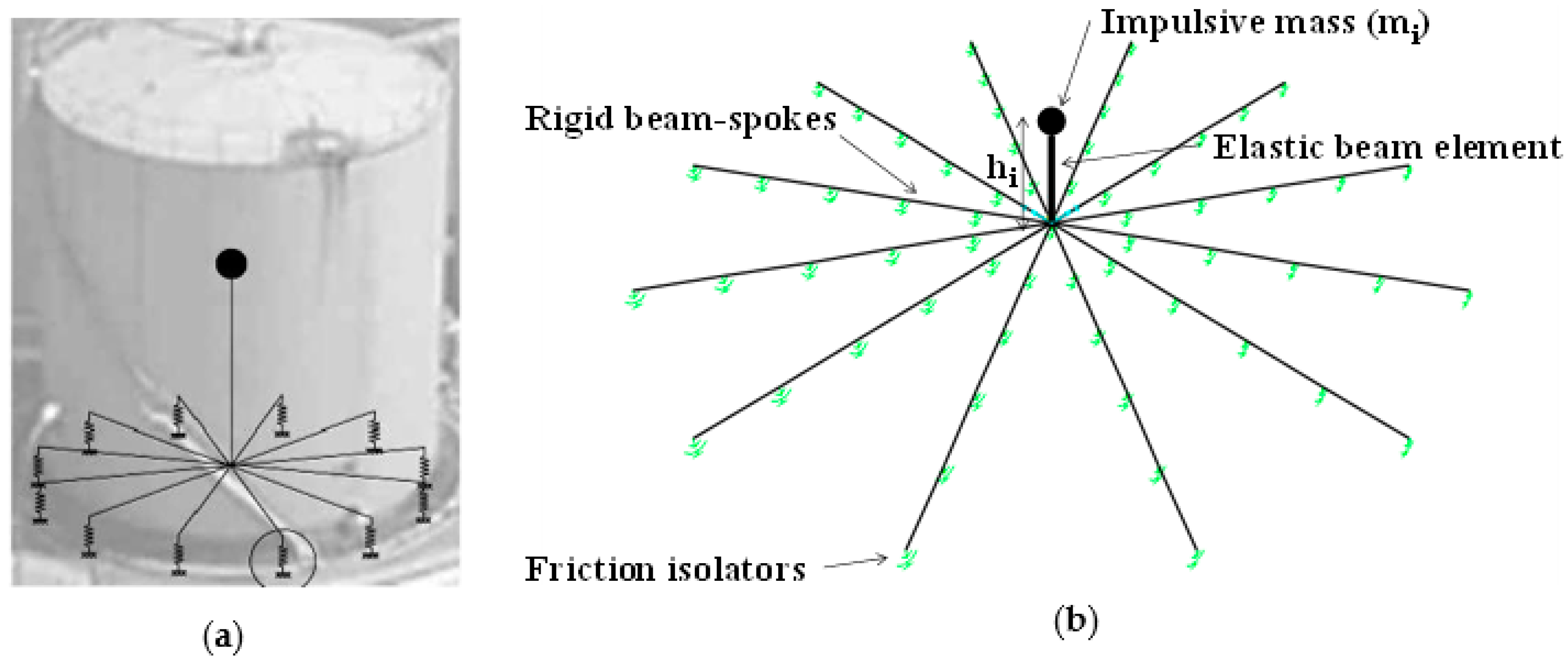
Consequently, the examined tank is represented by modifying the “Joystick model”, developed for fixed-base tanks by Bakalis et al. [29]. Due to the cylindrical geometry of the tank, the isolators are arranged following a symmetrical radial layout, as shown in the surrogate model of Figure 3. As displayed in Figure 3, the surrogate model consists of a vertical beam that carries the impulsive mass and it is supported by an adequate number of rigid beam spokes (e.g., 12 spokes in this investigation), which are placed on top of the sliding bearings. The beam spokes of the Joystick model are used to simulate the rigid base of the tank. Additionally, the guidelines of Eurocode 8—Part 4 [31] have been used to calculate the impulsive mass and the properties of the vertical elastic beam using the equivalent stiffness, ki, (equal to 7.8 × 10⁹ N/m) which corresponds to the impulsive period, Ti, (equal to 0.16 s) and mass, mi (equal to 5067 t). More details regarding the employed “Joystick model” can be found in [36]. This surrogate numerical model is quite reliable, as it accurately matches the impulsive fundamental period. Regarding the damping of the tank, it is set equal to 5%, as stated in Eurocode 8—Part 4 [31] recommendations for the ultimate limit state of liquid tanks. In the developed surrogate models, the lumped masses represent the weight of the content, applied at the base beam spokes of the tank, i.e., the vertical loads are imposed on the bearings. It is noted that the weight of the tank walls can be neglected, as it is only a small percentage (≈5%) of the total weight [37].
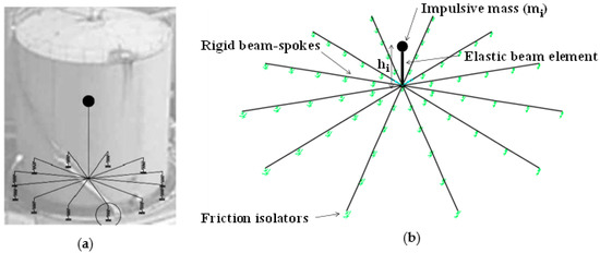
Figure 3.
Joystick models of: (a) a fixed-base and (b) a base-isolated squat tank (Reprinted from Computers and Structures, Volume 243, Alexandros Tsipianitis and Yiannis Tsompanakis, Optimizing the seismic response of base-isolated liquid storage tanks using swarm intelligence algorithms, Pages No. 106407, Copyright (2022), with permission from Elsevier).
As mentioned, the impulsive liquid component dominates the hydrodynamic response of the tanks. On the other hand, the convective liquid mass can be neglected, based on relevant studies (e.g., Christovasilis and Whittaker [35]; Rawat et al. [38]), in which it is presented that although the impulsive pressure is reduced due to seismic isolation, the convective pressure remains practically constant. Furthermore, the impact of the convective part of liquid content can be estimated separately [29]. Figure 4 compares the predominant periods of the selected accelerograms with the periods of the impulsive and convective liquid components of the examined squat tank. It has to be stressed that the fundamental period of the examined tank isolated with different bearing configurations ranges from 2.29 s to 3.23 s. As shown in Figure 4, the convective period is close to 7 s; thus, it is evident that the dynamic response of the tank is mainly influenced by its impulsive period, while sloshing phenomena are not expected to occur.
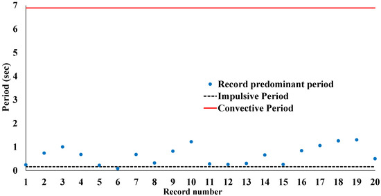
Figure 4.
Predominant periods of the selected accelerograms compared to liquid content component periods (Reprinted from Computers and Structures, Volume 243, Alexandros Tsipianitis and Yiannis Tsompanakis, Optimizing the seismic response of base-isolated liquid storage tanks using swarm intelligence algorithms, Pages No. 106407, Copyright (2022), with permission from Elsevier).
4.3. Numerical Modeling and Selected Records
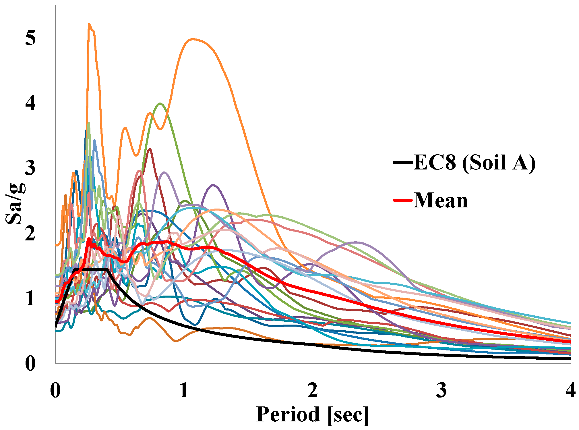
The dynamic analyses of the Joystick model supported on the various SFPB and TFPB isolator configurations have been performed using the finite-element software SAP2000 [39]. The suite of the near-fault ground motions derived from FEMA/SAC Steel Project [40] is used to test and optimize the performance of the isolators under strong impulses (https://nisee.berkeley.edu/elibrary/files/documents/data/strong_motion/sacsteel/motions/nearfault.html, accessed on 10 April 2017). The first ten acceleration time histories refer to natural records, while the remaining were derived artificially (as presented in Table 1). The special frequency content of these accelerograms is displayed in Figure 5, where all elastic response spectra for 5% damping are shown. Due to their scattering the mean spectrum is also shown and compared with Eurocode 8 (EC8) spectrum for Soil A. These accelerograms result in quite high displacements that can cause failure of the bearings [41]. This ground motion set is a well-established suite of impulsive excitations with very high PGA values (ranging from 0.45 g to 1.07 g) that is frequently used in seismic fragility analysis studies (e.g., Billah and Allam [42]).

Table 1.
Selected near-fault excitations.

Figure 5.
Acceleration elastic response spectra for 5% damping of the near-fault excitations (Reprinted from Computers and Structures, Volume 243, Alexandros Tsipianitis and Yiannis Tsompanakis, Optimizing the seismic response of base-isolated liquid storage tanks using swarm intelligence algorithms, Pages No. 106407, Copyright (2022), with permission from Elsevier).
Regarding base-isolated storage tanks, the use of a suitable ground motion set is required when implementing a performance-based design (PBD) framework. For this reason, a considerably large number of non-linear dynamic analyses have to be incrementally performed. According to Vamvatsikos and Cornell [43], the incremental dynamic analysis (IDA) process is implemented herein as follows [22,36]: (a) an efficient computational model is developed for performing IDA, (b) a suitable ground motion set is selected, (c) appropriate IM and engineering demand parameter(s) (EDP) are selected, and (d) scaling factors to perform the dynamic analyses and form the IM-EDP curves are selected. By implementing IDA methodology, the twenty selected time histories are suitably scaled to several intensity levels, and in turn are applied at the base-isolated surrogate models until isolator displacement limit is reached for the considered performance level [36].
Fast Non-linear Analysis (FNA) is adopted for the dynamic analyses, as it is suitable for structural systems in which the non-linear behavior is observed at the isolation system, while the superstructure response remains elastic [39]. Lastly, the global damping of the structural system is 5% for the ultimate limit state [31], while for the impulsive liquid component, it is 2% [44].
Regarding the SFPB isolators, the “Friction isolator” non-linear link element available in SAP2000 is used. This is a biaxial isolator, in which the two shear displacements as well as the friction parameters constitute a coupled system. A distinctive property of this link element is its post-slip stiffness along the horizontal directions due to the radius of curvature of the sliding surface. Moreover, it exhibits a gap behavior along the axial direction, while linear-effective stiffness is used for the three moment deformations. In addition, there is a proportional relationship between the compressive axial force and both friction and pendulum forces [39]. Accordingly, the following parameters need to be defined in the “Friction isolator” link element in SAP2000 for each SFPB isolator: effective stiffness and damping, non-linear stiffness, friction coefficient (slow/fast), rate parameter and the radius of curvature.
The “Triple-pendulum isolator” element is suitable for the accurate representation of TFPB [39]. It is modeled as a biaxial SFPB isolator, consisting of four concave sliding surfaces, i.e., two outer and two inner surfaces. The motion of the two inner surfaces can be considered as coupled due to kinematic conditions; this is represented as a series of three “Friction isolators”. The shear force–displacement curve can be adjusted by choosing different friction coefficients and radii of curvature. For this reason, different responses can be provided for various excitation levels, which are suitable when implementing a performance-based design (PBD) approach [12]. The following parameters are required in the “Triple-pendulum isolator” element in SAP2000: effective stiffness and damping, and separately for outer and inner surfaces, non-linear stiffness, friction coefficient, sliding rate parameter (slow/fast), radius of each sliding surface and related stop distance, i.e., the permitted transverse displacement along each sliding surface before encountering a stiff barrier [39]. Due to the more complex function of the “Triple-pendulum isolator” link element, the computational cost of the dynamic analyses for TFPB isolators is approximately 65% higher compared to SFPB.
5. Cuckoo Search Optimizer
The Cuckoo Search (CS) algorithm [45] programmed in MATLAB [46] (https://www.mathworks.com/matlabcentral/fileexchange/29809-cuckoo-search-cs-algorithm, accessed on 15 January 2018) is adopted to perform the required optimization calculations. Other evolutionary optimizers could also have been used and compared. However, it is noted that the focus of this study is not on the optimization algorithm, but on the novel optimization formulations. In complex and demanding engineering problems, the top priority is to use a robust and efficient optimization method, and certainly CS can be considered as such. Recently, Tsipianitis and Tsompanakis [47] presented improved CS algorithmic variants for constrained non-linear optimization benchmark problems. In that study, CS and its variants were compared with well-known metaheuristic optimizers (e.g., Particle Swarm Optimization, Fish Swarm Optimization, etc.) in several benchmark problems. In addition, modified versions of CS have been recently presented in the literature (e.g., Cuong-Le et al. [48]; Minh et al. [49]). Nonetheless, a detailed comparison of CS variants with other optimizers for the examined optimization problem is beyond the scope of the current study, although it could be examined in future extensions. Generally, such comparisons are useful in engineering optimization applications [47]; however, there are CS-based studies that have supported their scientific findings solely based on the CS optimizer, i.e., without comparing CS with other optimizers (e.g., [50]).
CS consists of a nature-inspired optimizer, which imitates the parasitic behavior of certain cuckoo species, while its performance is enhanced via Levy flights [51]. In general, three basic rules are used in CS formulation [45]:
- Each cuckoo bird lays only one egg (i.e., new design solution) and places it in a randomly selected nest.
- The best nests, i.e., with high-quality eggs, are maintained in the next generation.
- A constant number of available host nests is used, while there is a probability pa ∈ (0, 1) that the egg laid by a cuckoo is discovered by the host bird. In this case, the host bird can either discard the egg or simply abandon the nest and build a new one.
Certainly, the efficiency of evolutionary optimizers depends on the selection of their key parameters. However, for optimizers that are used for several years in various applications, the optimal range of values for the most crucial parameters has been well established. The most crucial parameters in CS are the number of nests, n, and the probability pa. Relevant studies have examined the impact of the values of these two variables in the performance of CS (e.g., [50,52]). In particular, Buaklee and Hongesombut [50] performed two sensitivity analyses: a) in the first case, the value of probability pa ranged from 0.05 to 0.5, while the number of nests was kept constant, i.e., n = 25; b) in the second case, the number of nests ranged from 10 to 50, while the discovering probability was kept constant, i.e., pa = 0.25. The results illustrated that the variation of the discovering probability and the number of nests did not hinder CS from obtaining the global optimum. Moreover, the results of such studies illustrated that the convergence rate is not very sensitive to the values of these two key parameters ([50,52]).
In this study, based on the recommendations of Yang and Deb [45], the number of nests is set equal to 25, while pa is 0.25. In addition, the replacement of a fraction pa of the n host nests with new nests, i.e., with new random design solutions, can be applied [45]. The objective is to use the new and probably superior solutions (cuckoos) to replace inferior solutions in the current nests. It is noted that CS can be extended to more complex formulations, in which each nest can contain multiple eggs that correspond to a set of solutions. In the present formulation, the simple approach is adopted, i.e., each nest has one egg. Regarding the selection of additional CS parameters, the following values have been used: Levy exponent β = 1.5 and step size a = 1 [45].
In the sequence, the basic steps of the CS algorithm are presented for a better understanding of the adopted optimization process. It should be mentioned that the MATLAB code of the standard CS optimizer has been properly structured into several functions in order to achieve higher computational efficiency. The main steps of the CS-based optimization process for all optimized SFPB and TFPB isolation schemes are as follows:
- Determination of the matrix nest (n × z) initially compiled from random numbers at each position, where n is the number of nests and z is the number of positions at the matrix. These numbers are integers in the range [1, B], where B is the number of isolators.
- Determination of the matrix fitness (n × 1), defining an initial random large number depending on the characteristics of the problem.
- Implementation of the function get best nest that aims to define the best solution of the objective function and its corresponding nest.
- Performing the iterative process, in which the objective function is compared with the determined bounds.
- Implementation of the function get cuckoos. The aim of this function is the determination of the step that results in a new nest via Levy flights.
- Implementation of the function simple bounds, where the content of matrix positions is checked.
- Implementation of the function get best nest, similar to step (3).
- Implementation of the function empty nests, where the probability of the alien egg to be found by the host bird is applied.
- Implementation of the function get best nest, similar to step (3).
- Check if the objective function is minimized at the specified bounds. When the condition is false, the algorithm returns to step (d). Otherwise, the algorithm converges. The convergence tolerance has been set equal to 0.001, while the maximum number of iterations is 5000.
6. Single and Dual Optimization Formulations
Generally, depending on its main aim, structural optimization can be classified into three main types [53]: sizing, shape and topology or layout optimization. There are numerous engineering applications based on single optimization formulations, while there are also dual approaches that combine the main types. For instance, a combined optimization approach was implemented by Jawad et al. [54] to simultaneously optimize the layout and members’ size of several benchmark truss structures. As mentioned in the introduction, the literature review revealed that there is no relevant study that has focused on the combined optimization of both the key parameters (i.e., sizing optimization) and the layout (i.e., optimal placement) of the isolators installed at the base of buildings or tanks. For this reason, single and dual optimization formulations for base-isolated tanks are presented herein, which can be considered a significant novelty compared to the authors’ recent study on sizing optimization of friction bearings [16].
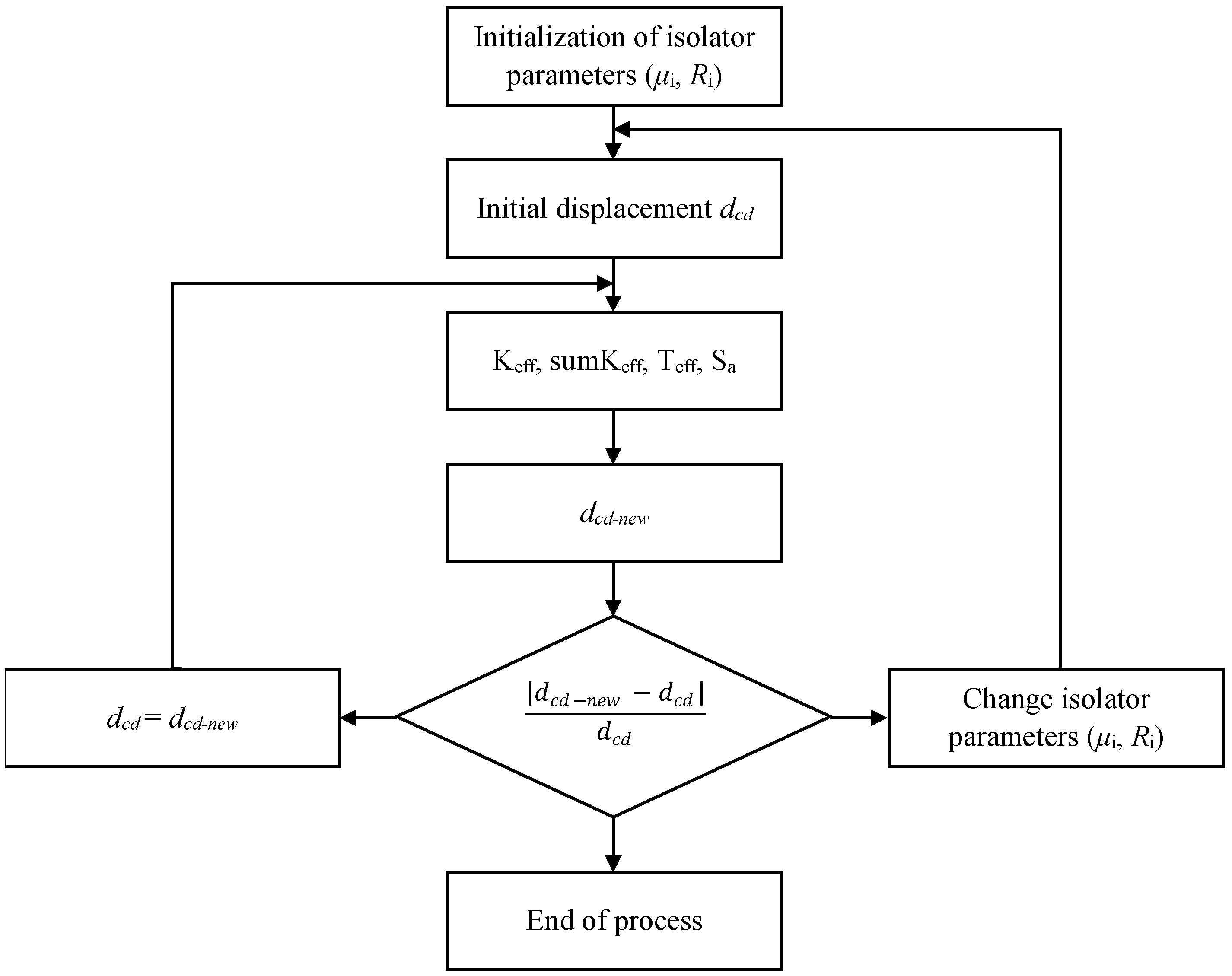
In the proposed single and combined optimization formulations, the CS optimizer is used for the minimization of the eccentricity (i.e., the distance between the centers of mass and rigidity of the isolation system) of liquid storage tanks isolated either by SFPB or TFPB. In this manner, the dynamic response of the system is not influenced by the higher modes and the torsional distress is minimized. In order to assess the effectiveness of the optimized isolation schemes, a comparison is performed with a reference design with standard parameters for the isolators, referred to as SFPB1 and TFPB1, which are derived using the equivalent linear force (ELF) procedure shown in Figure 6.
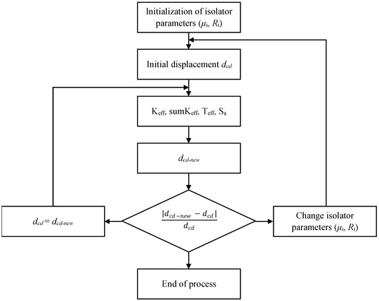
Figure 6.
Flowchart of the conventional ELF design process for single (SFPB1) and triple (TFPB1) isolators.
ELF is a process often applied for the preliminary design of base-isolation systems. More specifically, it is a repetitive procedure in which initial isolator parameters are selected. After the calculations, the isolator capacity should be equal to the target displacement. Otherwise, different design parameters are selected, and the process is repeated. This is schematically illustrated in Figure 6, where μi denotes the friction coefficient, Ri is the radius of curvature, dcd is the target displacement, Keff and Teff denote isolators effective stiffness and period, Sa is the spectral acceleration and dcd-new is the current displacement capacity. For the examined tank, the following conditions are assumed, according to Eurocode 8: Soil type A, importance factor, γi = 1.4, and bedrock acceleration, ag = 0.36 g.
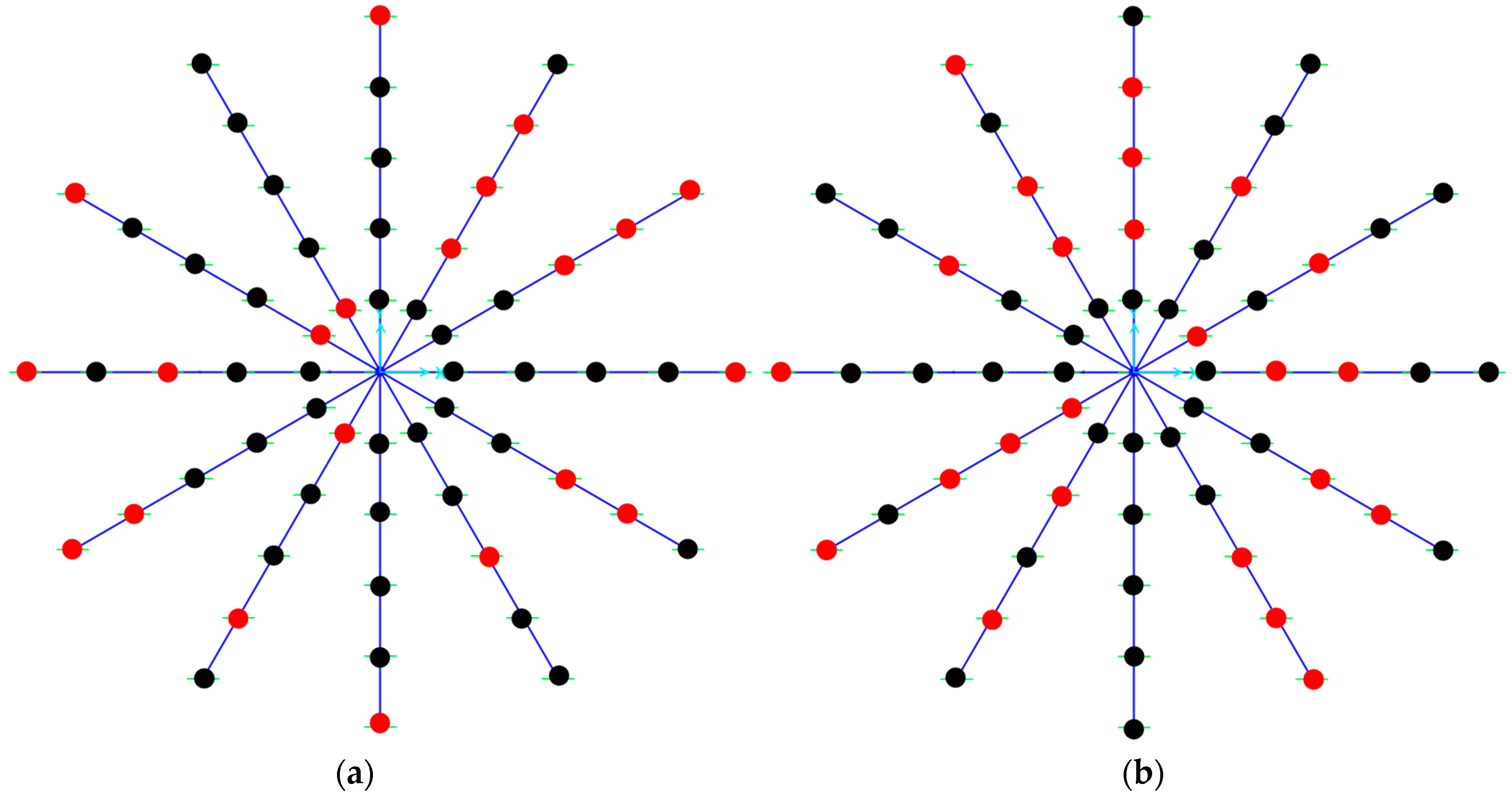
The first optimization approach, namely SFPB2 and TFPB2, focuses on the sizing optimization of the main parameters (i.e., radius of curvature and friction coefficients) of the two types of friction-based devices. In addition, combined optimization formulations, denoted as SFPB3 and TFPB3, have been developed. These approaches achieve the optimal placement of the minimum number of required bearings in conjunction with the sizing optimization of the friction coefficient and radius of curvature of sliding surface(s). More specifically, in each optimization cycle of the dual optimization formulations, CS randomly assigns isolators with zero parameters to assess if their placement is fully necessary to best serve the problem needs, according to the objective and constraints functions which are presented in the sequence. This process is repeated in every iteration and results in the minimum possible number of isolators for the specific prearranged layout, as shown in Figure 7.
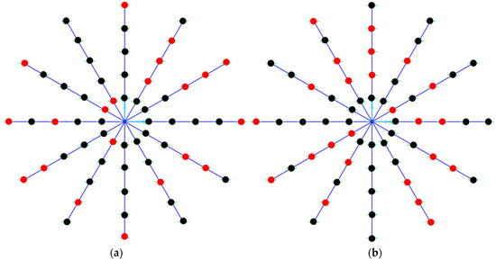
Figure 7.
Optimal placement for: (a) SFPB3 and (b) TFPB3 isolators, in which black dots denote active bearings, while “zero-isolators” are represented with red dots.
It should be noted that both single and dual optimization approaches result in isolators with different parameters (i.e., μi, Ri). When friction coefficients are not the same for all friction devices, the center of superstructure mass may not coincide with the isolator center of rigidity [55]. In general, variations of isolator properties can cause accidental torsion of the superstructure. For instance, Matsagar and Jangid [56] stated that eccentricities related to different isolator parameters can affect the response of the system. In addition, the placement of the isolators—in conjunction with structural irregularities—can affect the torsional response of the superstructure [57]. These important issues are taken into account in the proposed optimization formulations via the minimization of the isolators’ eccentricity, as described in the sequence.
In the current study, a realistic range of values is used for the design variables in the optimization calculations, which are treated as continuous parameters. More specifically, the values of the friction coefficient and the radius of curvature range between 0.03 and 0.08 and 1 to 5 m, respectively, for SFPB [58] as well as the outer sliding surfaces of TFPB. With respect to the inner surfaces of TFPB isolators, the following values are considered, e.g., R1,4 = 3·R2,3 and μ1,4 = 3·μ2,3, as recommended by Fadi and Constantinou [59]. Subscripts correspond to the sliding surface of the bearings, as shown in Figure 1. Certainly, in engineering projects, additional technical/economical constraints could be imposed on these parameters due to budget limitations, availability and ease of implementation (e.g., grouping of isolators with small variations, using discrete values for design variables, etc.).
As previously mentioned, when isolators’ parameters are different, adverse torsional effects can affect the superstructure. In order to minimize the torsional response of the tank, the objective function is set in both formulations as follows:
in which emin refers to the minimum eccentricity of the base-isolated tank, since xcw and ycw denote the coordinates of the center of mass, while xcr and ycr are the coordinates of the center of rigidity, which are calculated as follows:
where xi, yi are the coordinates of the selected nodes at the tank’s base, Pvertical,i refers to the applied vertical load and Keff,i denotes the effective stiffness of each isolator.
The constraints in both optimization schemes are related to the isolated system response, according to the recommendations of Kelly [60], CEN [31] and Bisch et al. [61]:
in which T is the fundamental period of the fixed-base system, Teff refers to the effective period and βeff denotes the effective damping of the isolation system. Lastly, an additional constraint is imposed on the load capacity of each isolator, as follows:
where Pcritical is the critical load defined by Constantinou et al. [62]. This constraint is vital to the dual optimization process; as the number of “zero” isolators is reduced, the load on the remaining active bearings is increased up to the critical limit.
7. Numerical Results
7.1. Conventional Design Results
As previously mentioned, the SFPB1 and TFPB1 configurations are derived via the heuristic ELF design procedure (Figure 6) without implementing any optimization. They result in more conservative solutions and they are used for comparison with the proposed single- and dual- optimized schemes. Due to the geometry of the tank, the process resulted in 60 identical isolators, symmetrically placed in both schemes, as shown in Figure 3. It is noted that rectangular isolator grids are usually used in buildings, while, based on engineering experience and problem characteristics, non-identical isolators can be applied. For instance, Mazza and Mazza [63], based on axial load variation, heuristically selected SFPB with different properties to more efficiently isolate a six-story reinforced concrete building, with an L-shaped plan under near-fault excitations.
The ELF process results in an SFPB1 scheme with 60 SFPB isolators with identical properties, i.e., μ = 0.03 and R = 3.2 m. The fundamental period of the system is 3.23 s, the effective damping is 24.4% and the displacement capacity is 0.29 m. Analogously, the uniform parameters of the 60 isolators in TFPB1 scheme are: friction coefficient values for the outer sliding surfaces, μ1 = μ4 = 0.09 and the inner sliding surfaces, μ2 = μ3 = 0.03, radius of curvature values for the outer surfaces, R1 = R4 = 3.2 m, and the inner surfaces, R2 = R3 = 1.07 m. The fundamental period of the system is 2.87 s, the effective damping is 22.84% and the displacement capacity is 0.784 m, much higher compared to SFPB1, which enables them to withstand higher PGA levels, as will be shown in the sequence.
7.2. Optimization Results
In this section, both single and dual optimization results using a CS algorithm for the examined squat tank isolated either by SFPB (SFPB2 and SFPB3) or TFPB (TFPB2 and TFPB3) are presented. The main results are summarized in Table 2. It can be easily observed from Table 2 that only 39 isolators are derived from the dual optimization process SFPB3 (Figure 7a) compared to the conventional design and sizing optimization approaches, where 60 SFPB are installed at the base of the tank. The requirements regarding the eccentricity minimization and isolators constraints are fully satisfied. Analogously, when the tank is protected via TFPB isolators, the TFPB3 optimization formulation leads to 36 bearings (Table 2 and Figure 7b). It should be noted that for both single and dual optimization schemes, the basic parameters (i.e., μi, Ri) can be different for each isolator, while bearings with small differences can be grouped as mentioned earlier. Hence, the displacement capacity of the whole system is bounded by the isolator(s) with minimum displacement capacity.
Table 2.
Optimization results for all optimized isolations configurations.
In addition, the capacity of each bearing has a direct effect on its cost and, consequently, the total cost of the whole system. Nonetheless, the differences of the bearings’ properties in dual configurations (with reduced numbers, i.e., 39 and 36 for SFPB3 and TFPB3, respectively) are small compared to the corresponding ones in the other two schemes with a constant number (i.e., 60). This is verified by the fact that the displacement capacity in Table 2 is the same for the two optimization schemes (0.28 m and 0.72 m for single and triple bearings), while there are small differences from the slightly higher values of the conventional design approach (0.29 m and 0.784 m, respectively). Therefore, the overall cost for the optimized designs derived utilizing the dual optimization process is much smaller compared with those of single optimization and conventional design procedures for both bearing types.
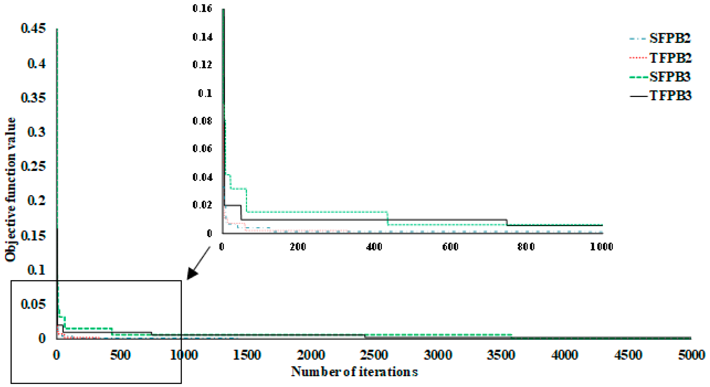
Figure 8 depicts the convergence histories of the optimization process using a CS optimizer for the different optimization formulations that have been examined in this study. A “truncated” plot is also added into the main graph for a better representation of the results. As can be noticed, the combined optimization formulations (SFPB3 and TFPB3) required more iterations to converge compared to the single sizing optimization formulations (SFPB2 and TFPB2) due to the additional complexities of the design space. Regarding the isolator type, TFPB3 required more iterations to converge compared to SFPB3, while TFPB2 converged faster than SFPB2.
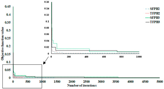
Figure 8.
Convergence histories.
7.3. Isolator Fragility Curves
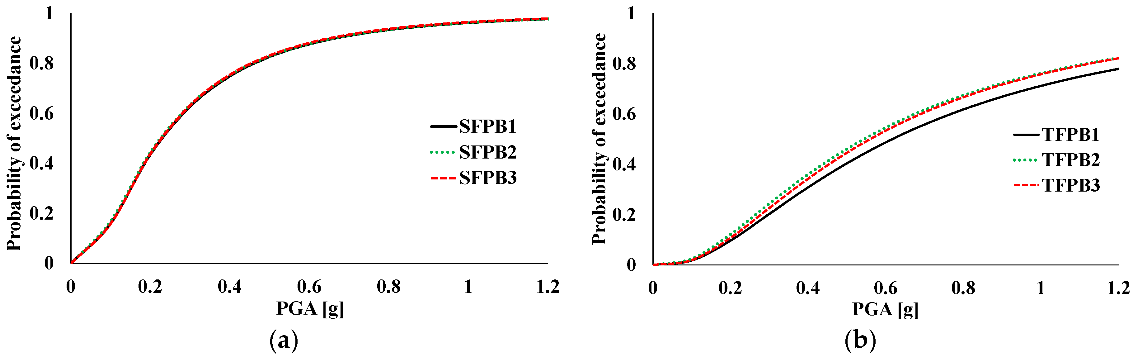
The fragility curves of storage tanks isolated via SFPB and TFPB with either standard design or optimized parameters are presented in Figure 9. They have been calculated in terms of isolator displacements for various PGA levels. As mentioned earlier, the maximum displacement of SFPB and TFPB is related to the Maximum Credible Earthquake (MCE) hazard level, with probability of exceedance of 2% in 50 years. In particular, the results for the three approaches are illustrated for each isolator type (i.e., SFPB1, SFPB2, SFPB3 and TFPB1, TFPB2, TFPB3, respectively). It can be observed from Figure 9a that in the case of single bearings, the fragility curves of the conservative SFPB1 design are identical to those of SFPB2 and SFPB3 single- and dual-optimized- schemes although the SFPB3 scheme contains significantly fewer isolators. On the other hand, the fragility curves of the tank isolated with triple bearings shown in Figure 9b illustrate that TFPB1 presents slightly better results compared to the other two more cost-efficient approaches, TFPB2 and TFPB3, which result in almost identical results.

Figure 9.
Fragility curves for the storage tank equipped with: (a) SFPB and (b) TFPB schemes.
7.4. Superstructure Accelerations
In contrast with base-isolated tanks, the probability of failure for fixed-base liquid storage tanks presents high values even for medium intensity levels [26]. This can be attributed to the significantly reduced accelerations transmitted to the superstructure due to base isolation; thus, the isolated tank exhibits a linear response. In this manner, tank wall damages and liquid content leakages can be avoided for the usually expected range of PGA values, while any system failure (i.e., for the tank and the isolation) is mainly associated with the exceedance of the allowable SFPB and TFPB displacement capacity, as presented in the form of the fragility curves in Figure 9.
To illustrate the beneficial role of the isolation, Figure 10 presents the base accelerations transmitted to the superstructure (i.e., measured just above the isolators) for all schemes. More specifically, the results for all the examined approaches and isolator types are depicted for the maximum imposed values for every accelerogram, i.e., at the last step of the fragility curve generation process. As expected, the accelerations transmitted to the superstructure are notably reduced for all isolation configurations. This is more pronounced in the case of triple bearings, which, due to their increased capacity, can withstand much higher PGA levels compared to the single bearings, as can be seen by comparing the PGA values used to obtain the fragility curves in the two plots of Figure 9. Analogously, triple bearings exhibit much higher maximum acceleration values in Figure 10, in which the presented results correspond to the ultimate scaled values for each excitation. It can also be observed that for both isolator types, the dual optimization approach (i.e., SFPB3 and TFPB3) provides slightly better results compared to the other two approaches, especially for extreme acceleration values for certain accelerograms, e.g., #9 (Kobe, 1995), #16 (Palos Verdes 1) and #19 (Palos Verdes 4).
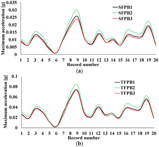
Figure 10.
Base accelerations of the storage tank for: (a) SFPB and (b) TFPB isolation schemes.
8. Conclusions
The present study aims to improve the dynamic response of isolated tanks in a cost-efficient manner by optimizing both the isolator layout and critical parameters, i.e., the friction coefficient and radius of curvature of each (single or multiple) sliding surface. According to the review of the relevant literature, there is no relevant study that has focused on the combined optimization of both the key parameters (i.e., sizing optimization) and the layout (i.e., optimal placement) of the isolators installed at the base of buildings or tanks. For this purpose, the constrained optimization of SFPB and TFPB isolators installed at the base of liquid storage tanks has been investigated herein. More specifically, the dynamic performance of tanks isolated by SFPB or TFPB has been optimized firstly with respect to the properties of the isolators and then together with their optimal placement at tank’s base. For this purpose, the seismic vulnerability—in terms of isolators displacements and superstructure accelerations—has been examined for each optimized configuration. In order to achieve an optimal balance between computational accuracy and efficiency, an efficient surrogate model has been used for the realistic representation of the hydrodynamic response of the tank.
According to the presented results, the main findings of this preliminary investigation can be summarized as follows:
- The dual optimization approach (SFPB3, TFPB3) leads to a substantially more cost-efficient design for both isolator types. More specifically, SFPB3 and TFPB3 resulted in 39 and 36 isolators, respectively, for the examined squat cylindrical tank. On the other hand, the conventional design (SFPB1, TFPB1) and the single optimization (SFPB2, TFPB2) procedures required 60 isolators, regardless of the bearing type. Moreover, despite this significant reduction in the required isolators, the differences in the isolators’ properties—and cost—are small compared to full configurations. Thus, the total cost of the isolation system in dual schemes is much less for both bearing types.
- Regarding the fragility curves of the isolators, marginal differences were noticed only in the case of TFPB, while for SFPB, the results were identical to the conservative design approach for both single and dual optimization formulations.
- A significant reduction in accelerations transmitted to the superstructure was observed for all isolation schemes, especially in the case of TFPB, which is slightly increased in the case of dual optimization configurations and extreme PGA levels.
- For both isolator types, the single (i.e., only sizing) optimization converged faster than the dual formulations due to the additional complexity related to the optimal placement of the bearings.
Consequently, by applying the proposed optimization methodology, optimal configurations with reduced number of isolators could be used in large-scale projects, leading to a more cost-effective design of base-isolated structures. Certainly, further investigation must be performed, including a more detailed cost analysis regarding the topology of the isolators (grid type and/or non-constant locations) and their sizing parameters. In addition, the optimization problem could be formulated with discrete design variables and/or by grouping isolators with similar properties, since such alternative optimized designs would be more viable from a practical point of view. Furthermore, a multi-objective optimization formulation of hybrid isolation systems—consisting of friction-based isolators and supplemental dampers [64], tuned mass dampers [65,66] or semi-active/active control devices [67]—can also be examined as an extension of this work.
Author Contributions
Conceptualization, A.T. and Y.T.; methodology, A.T., A.S. and Y.T.; software, A.T. and A.S.; validation, A.T. and A.S.; formal analysis, A.T.; investigation, A.T., A.S. and Y.T.; resources, A.T. and Y.T.; data curation, A.T. and A.S.; writing—original draft preparation, A.T. and Y.T.; writing—review and editing, A.T. and Y.T.; visualization, A.T.; supervision, Y.T.; project administration, Y.T. All authors have read and agreed to the published version of the manuscript.
Funding
This research received no external funding.
Acknowledgments
This research has been generously supported by Emmanouil Michailakis via a PhD scholarship for the first author. The scholarship is gratefully acknowledged.
Conflicts of Interest
The authors declare no conflict of interest. No funders had any role in the design of the study; in the collection, analyses, or interpretation of data; in the writing of the manuscript; or in the decision to publish the results.
List of Notations
| 3D | Three-dimensional |
| CS | Cuckoo Search |
| DBE | Design Basis Earthquake |
| EDP | Engineering Demand Parameter |
| ELF | Equivalent Linear Force |
| FNA | Fast Nonlinear Analysis |
| GA | Genetic Algorithm |
| HS | Harmony Search |
| IDA | Incremental Dynamic Analysis |
| IM | Intensity Measure |
| MCE | Maximum Credible Earthquake |
| NSGA | Non-Dominated Sorting Genetic Algorithm |
| PBD | Performance-Based Design |
| PGA | Peak Ground Acceleration |
| PGV | Peak Ground Velocity |
| SFPB | Single Friction Pendulum Bearing |
| SLE | Service Level Earthquake |
| TFPB | Triple Friction Pendulum Bearing |
| TID | Tuned Inerter Damper |
| TMD | Tuned Mass Damper |
| TVMD | Tuned Viscous Mass Damper |
References
- Housner, G.W. The Dynamic Behavior of Water Tanks. Bull. Seismol. Soc. Am. 1963, 53, 381–387. [Google Scholar] [CrossRef]
- Veletsos, A.S.; Tang, Y.; Tang, H.T. Dynamic Response of Flexibly Supported Liquid-Storage Tanks. J. Struct. Eng. 1992, 118, 264–283. [Google Scholar] [CrossRef]
- Malhotra, P.K. Seismic Response of Soil-Supported Unanchored Liquid-Storage Tanks. J. Struct. Eng. 1997, 123, 440–450. [Google Scholar] [CrossRef]
- Egbelakin, T.; Ogunmakinde, O.E.; Omotayo, T.; Sojobi, A. Demystifying the Barriers and Motivators for the Adoption of Base Isolation Systems in New Zealand. Buildings 2022, 12, 522. [Google Scholar] [CrossRef]
- Jangid, R.S. Optimum Frictional Elements in Sliding Isolation Systems. Comput. Struct. 2000, 76, 651–661. [Google Scholar] [CrossRef]
- Jangid, R.S. Optimum Friction Pendulum System for Near-Fault Motions. Eng. Struct. 2005, 27, 349–359. [Google Scholar] [CrossRef]
- Bucher, C. Probability-Based Optimal Design of Friction-Based Seismic Isolation Devices. Struct. Saf. 2009, 31, 500–507. [Google Scholar] [CrossRef]
- Calafell, R.L.; Roschke, P.N.; de la Llera, J.C. Optimized Friction Pendulum and Precast-Prestressed Pile to Base-Isolate a Chilean Masonry House. Bull. Earthq. Eng. 2010, 8, 1019–1036. [Google Scholar] [CrossRef]
- Charmpis, D.C.; Komodromos, P.; Phocas, M.C. Optimized Earthquake Response of Multi-Storey Buildings with Seismic Isolation at Various Elevations. Earthq. Eng. Struct. Dyn. 2012, 41, 2289–2310. [Google Scholar] [CrossRef]
- Chung, L.L.; Kao, P.S.; Yang, C.Y.; Wu, L.Y.; Chen, H.M. Optimal Frictional Coefficient of Structural Isolation System. JVC/J. Vib. Control 2015, 21, 525–538. [Google Scholar] [CrossRef]
- Nigdeli, S.M.; Bekdaş, G.; Alhan, C. Optimization of Seismic Isolation Systems via Harmony Search. Eng. Optim. 2014, 46, 1553–1569. [Google Scholar] [CrossRef]
- Moeindarbari, H.; Taghikhany, T. Seismic Optimum Design of Triple Friction Pendulum Bearing Subjected to Near-Fault Pulse-like Ground Motions. Struct. Multidiscip. Optim. 2014, 50, 701–716. [Google Scholar] [CrossRef]
- Das, S.; Gur, S.; Mishra, S.K.; Chakraborty, S. Optimal Performance of Base Isolated Building Considering Limitation on Excessive Isolator Displacement. Struct. Infrastruct. Eng. 2015, 11, 904–917. [Google Scholar] [CrossRef]
- Castaldo, P.; Ripani, M. Optimal Design of Friction Pendulum System Properties for Isolated Structures Considering Different Soil Conditions. Soil Dyn. Earthq. Eng. 2016, 90, 74–87. [Google Scholar] [CrossRef]
- Zou, S.; Heisha, W.; Tan, P. Performance-Based Dynamic Optimal Design for Isolated Structures with Multiple-Coupling Friction Dampers. Adv. Struct. Eng. 2020, 23, 2149–2162. [Google Scholar] [CrossRef]
- Tsipianitis, A.; Tsompanakis, Y. Optimizing the Seismic Response of Base-Isolated Liquid Storage Tanks Using Swarm Intelligence Algorithms. Comput. Struct. 2021, 243, 106407. [Google Scholar] [CrossRef]
- Çerçevik, A.E.; Avşar, Ö.; Hasançebi, O. Optimum Design of Seismic Isolation Systems Using Metaheuristic Search Methods. Soil Dyn. Earthq. Eng. 2020, 131, 106012. [Google Scholar] [CrossRef]
- Li, Y.; Li, S.; Chen, Z. Optimal Design and Effectiveness Evaluation for Inerter-based Devices on Mitigating Seismic Responses of Base isolated Structures. Earthq. Eng. Eng. Vib. 2021, 20, 1021–1032. [Google Scholar] [CrossRef]
- Ocak, A.; Nigdeli, S.M.; Bekda, G. Optimization of Seismic Base Isolation System Using Adaptive Harmony Search Algorithm. Sustainability 2022, 14, 7456. [Google Scholar] [CrossRef]
- Furinghetti, M.; Pavese, A. Definition of a Simplified Design Procedure of Seismic Isolation Systems for Bridges. Struct. Eng. Int. 2020, 30, 381–386. [Google Scholar] [CrossRef]
- Zayas, V.; Low, S.; Mahin, S. The FPS Earthquake Resisting System; EERC Report No. UCB/EERC-87/01; University of California: Berkeley, CA, USA, 1987. [Google Scholar]
- Tsipianitis, A.; Tsompanakis, Y. Seismic Vulnerability Assessment of Liquid Storage Tanks Isolated by Sliding-Based Systems. Adv. Civ. Eng. 2018, 2018, 5304245. [Google Scholar] [CrossRef]
- Salzano, E.; Iervolino, I.; Fabbrocino, G. Seismic Risk of Atmospheric Storage Tanks in the Framework of Quantitative Risk Analysis. J. Loss Prev. Process Ind. 2003, 16, 403–409. [Google Scholar] [CrossRef]
- Alliance American Lifelines (ALA). Seismic Fragility Formulations for Water Systems; ASCE: Reston, VA, USA, 2001. [Google Scholar]
- Bakalis, K.; Vamvatsikos, D.; Fragiadakis, M. Seismic Risk Assessment of Liquid Storage Tanks via a Nonlinear Surrogate Model. Earthq. Eng. Struct. Dyn. 2017, 46, 2851–2868. [Google Scholar] [CrossRef]
- Saha, S.K.; Matsagar, V.; Chakraborty, S. Uncertainty Quantification and Seismic Fragility of Base-Isolated Liquid Storage Tanks Using Response Surface Models. Probabilistic Eng. Mech. 2016, 43, 20–35. [Google Scholar] [CrossRef]
- Baker, J.W. Efficient Analytical Fragility Function Fitting Using Dynamic Structural Analysis. Earthq. Spectra 2015, 31, 579–599. [Google Scholar] [CrossRef]
- Haroun, M.A. Vibration Studies and Tests of Liquid Storage Tanks. Earthq. Eng. Struct. Dyn. 1983, 11, 179–206. [Google Scholar] [CrossRef]
- Bakalis, K.; Fragiadakis, M.; Vamvatsikos, D. Surrogate Modeling for the Seismic Performance Assessment of Liquid Storage Tanks. J. Struct. Eng. 2017, 143, 04016199. [Google Scholar] [CrossRef]
- Konstandakopoulou, F.D.; Hatzigeorgiou, G.D. Water and Wastewater Steel Tanks under Multiple Earthquakes. Soil Dyn. Earthq. Eng. 2017, 100, 445–453. [Google Scholar] [CrossRef]
- CEN. Eurocode 8—Design of Structures for Earthquake Resistance—Part 4: Silos, Tanks and Pipelines EN 1998-4; European Committee for Standardization: Brussels, Belgium, 2006. [Google Scholar]
- American Petroleum Institute. API 650: Welded Steel Tanks for Oil Storage, 11th ed.; American Petroleum Institute: Washington, DC, USA, 1998. [Google Scholar]
- NZEE. Seismic Design of Storage Tanks—Recommendations of the New Zealand Society for Earthquake Engineering; New Zealand Society of Earthquake Engineering: Christchurch, New Zealand, 2009. [Google Scholar]
- IITK-GSDMA. Guidlines for Seismic Design of Liquid Storage Tanks; National Information Center of Earthquake Engineering: Kanpur, India, 2007. [Google Scholar]
- Christovasilis, I.P.; Whittaker, A.S. Seismic Analysis of Conventional and Isolated LNG Tanks Using Mechanical Analogs. Earthq. Spectra 2008, 24, 599–616. [Google Scholar] [CrossRef]
- Tsipianitis, A.; Tsompanakis, Y. Impact of Damping Modeling on the Seismic Response of Base-Isolated Liquid Storage Tanks. Soil Dyn. Earthq. Eng. 2019, 121, 281–292. [Google Scholar] [CrossRef]
- Panchal, V.R.; Jangid, R.S. Variable Friction Pendulum System for Seismic Isolation of Liquid Storage Tanks. Nucl. Eng. Des. 2008, 238, 1304–1315. [Google Scholar] [CrossRef]
- Rawat, A.; Matsagar, V.A.; Nagpal, A.K. Numerical Study of Base-Isolated Cylindrical Liquid Storage Tanks Using Coupled Acoustic-Structural Approach. Soil Dyn. Earthq. Eng. 2019, 119, 196–219. [Google Scholar] [CrossRef]
- CSI Computers and Structures Inc. SAP2000 Version 20. Integrated Software for Structural Analysis and Design, Analysis Reference Manual; Computers and Structures Inc.: Berkeley, CA, USA, 2017. [Google Scholar]
- Sommerville, P.; Smith, N.; Punyamurthula, S.; Ji, S. Development of Ground Motion Time Histories for Phase 2 of the FEMA/SAC Steel Project; SAC: Richmond, CA, USA, 1997. [Google Scholar]
- Nagarajaiah, S.; Ferrell, K. Stability of Elastomeric Seismic Isolation Bearings. J. Struct. Eng. 1999, 125, 946–954. [Google Scholar] [CrossRef]
- Billah, A.H.M.; Alam, M. Seismic Fragility Assessment of Concrete Bridge Pier Reinforced with Superelastic Shape Memory Alloy. Earthq. Spectra 2015, 31, 1515–1541. [Google Scholar] [CrossRef]
- Vamvatsikos, D.; Cornell, C. Incremental Dynamic Analysis. Earthq. Eng. Struct. Dyn. 2002, 31, 491–514. [Google Scholar] [CrossRef]
- Malhotra, P.K.; Wenk, T.; Wieland, M. Simple Procedure for Seismic Analysis of Liquid-Storage Tanks. Struct. Eng. Int. 2000, 10, 197–201. [Google Scholar] [CrossRef]
- Yang, X.-S.; Deb, S. Cuckoo Search via Lvy flights. In Proceeding of the 2009 World Congress Nature & Biologically Inspired Computing (NaBIC), Coimbatore, India, 9–11 December 2009; pp. 210–214. [Google Scholar] [CrossRef]
- Mathworks Inc. Matlab R2015a; Mathworks Inc.: Natick, MA, USA, 2015. [Google Scholar]
- Tsipianitis, A.; Tsompanakis, Y. Improved Cuckoo Search Algorithmic Variants for Constrained Nonlinear Optimization. Adv. Eng. Softw. 2020, 149, 102865. [Google Scholar] [CrossRef]
- Cuong-Le, T.; Minh, H.-L.; Khatir, S.; Wahab, M.A.; Tran, M.T.; Mirjalili, S. A Novel Version of Cuckoo Search Algorithm for Solving Optimization Problems. Expert Syst. Appl. 2021, 186, 115669. [Google Scholar] [CrossRef]
- Minh, H.; Sang-to, T.; Wahab, M.A.; Cuong-le, T. Structural Damage Identification in Thin-Shell Structures Using a New Technique Combining Finite Element Model Updating and Improved Cuckoo Search Algorithm. Adv. Eng. Softw. 2022, 173, 103206. [Google Scholar] [CrossRef]
- Buaklee, W.; Hongesombut, K. Optimal DG Allocation in a Smart Distribution Grid Using Cuckoo Search Algorithm. ECTI Trans. Electr. Eng. Electron. Commun. 2013, 11, 16–22. [Google Scholar] [CrossRef]
- Pavlyukevich, I. Lévy Flights, Non-Local Search and Simulated Annealing. J. Comput. Phys. 2007, 226, 1830–1844. [Google Scholar] [CrossRef]
- Yang, X.S.; Deb, S. Engineering Optimisation by Cuckoo Search. Int. J. Math. Model. Numer. Optim. 2010, 1, 330–343. [Google Scholar] [CrossRef]
- Papadrakakis, M.; Lagaros, N.D.; Tsompanakis, Y.; Plevris, V. Large Scale Structural Optimization: Computational Methods and Optimization Algorithms. Arch. Comput. Methods Eng. 2001, 8, 239–301. [Google Scholar] [CrossRef]
- Jawad, F.K.J.; Ozturk, C.; Dansheng, W.; Mahmood, M.; Al-Azzawi, O.; Al-Jemely, A. Sizing and Layout Optimization of Truss Structures with Artificial Bee Colony Algorithm. Structures 2021, 30, 546–559. [Google Scholar] [CrossRef]
- Saitta, F.; Clemente, P.; Buffarini, G.; Bongiovanni, G.; Salvatori, A.; Grossi, C. Base Isolation of Buildings with Curved Surface Sliders: Basic Design Criteria and Critical Issues. Adv. Civ. Eng. 2018, 2018, 1569683. [Google Scholar] [CrossRef]
- Matsagar, V.A.; Jangid, R.S. Base-Isolated Building with Asymmetries Due to the Isolator Parameters. Adv. Struct. Eng. 2005, 8, 603–620. [Google Scholar] [CrossRef]
- Ozer, E.; Inel, M.; Cayci, B.T. Seismic Behavior of LRB and FPS Type Isolators Considering Torsional Effects. Structures 2022, 37, 267–283. [Google Scholar] [CrossRef]
- Zayas, V. Personal Communication, 2017.
- Fadi, F.; Constantinou, M.C. Evaluation of Simplified Methods of Analysis for Structures with Triple Friction Pendulum Isolators. Earthq. Eng. Struct. Dyn. 2010, 39, 5–22. [Google Scholar] [CrossRef]
- Kelly, J.M. Earthquake-Resistant Design with Rubber, 2nd ed.; Springer: London, UK, 1997. [Google Scholar] [CrossRef]
- Bisch, P.; Carvalho, E.; Degee, H.; Fajfar, P.; Fardis, M.; Franchin, P.; Kreslin, M.; Pecker, A.; Pinto, P.; Plumier, A.; et al. Eurocode 8: Seismic Design of Buildings Worked Examples; Publications Office of the European Union: Luxembourg, 2012. [Google Scholar] [CrossRef]
- Constantinou, M.C.; Kalpakidis, I.; Filiatrault, A.; Lay, R.A.E. LRFD-Based Analysis and Design Procedures for Bridge Bearings and Seismic Isolators; University at Buffalo: Buffalo, NY, USA; State University of New York: New York, NY, USA, 2011. [Google Scholar]
- Mazza, F.; Mazza, M. Nonlinear Seismic Analysis of Irregular R.C. Framed Buildings Base-Isolated with Friction Pendulum System under near-Fault Excitations. Soil Dyn. Earthq. Eng. 2016, 90, 299–312. [Google Scholar] [CrossRef]
- Tsipianitis, A.; Tsompanakis, Y. Improving the Seismic Performance of Base-Isolated Liquid Storage Tanks with Supplemental Linear Viscous Dampers. Earthq. Eng. Eng. Vib. 2022, 21, 269–282. [Google Scholar] [CrossRef]
- Hessabi, R.M.; Mercan, O.; Ozturk, B. Exploring the Effects of Tuned Mass Dampers on the Seismic Performance of Structures with Nonlinear Base Isolation Systems. Earthq. Struct. 2017, 12, 285–296. [Google Scholar] [CrossRef]
- Labaf, D.Z.; De Angelis, M.; Basili, M. Multi-objective Optimal Design and Seismic Assessment of an Inerter-based Hybrid Control System for Storage Tanks. Bull. Earthq. Eng. 2022, 43, 1091–1099. [Google Scholar] [CrossRef]
- Basu, B.; Bursi, O.S.; Casciati, F.; Casciati, S.; Del Grosso, A.; Domaneschi, M.; Faravelli, L.; Holnicki-Szulc, J.; Irschik, H.; Krommer, M.; et al. A European Association for the Control of Structures Joint Perspective. Recent Studies in Civil Structural Control across Europe. Struct. Control Health Monit. 2014, 21, 1414–1436. [Google Scholar] [CrossRef]


Publisher’s Note: MDPI stays neutral with regard to jurisdictional claims in published maps and institutional affiliations. |
© 2022 by the authors. Licensee MDPI, Basel, Switzerland. This article is an open access article distributed under the terms and conditions of the Creative Commons Attribution (CC BY) license (https://creativecommons.org/licenses/by/4.0/).