Abstract
Frequency diverse array multiple-input multiple-output (FDA-MIMO) radar solves the problem of angle pointing and range pointing during beam transmission due to its unique range-angle dimension dependent, which gives it good characteristics against main lobe deceptive jamming. Moreover, the current single range dimension deceptive jamming is easy to be identified and cannot form an effective jamming effect on FDA-MIMO radar. To address this problem, this paper proposes a compound jamming method of suppression and range deceptive against FDA-MIMO beamforming. Compared with the traditional deceptive jamming method, this method can reasonably utilize the beam gain, and minimum variance distortionless response (MVDR) adaptive beamforming cannot significantly reduce the power of the jamming, thus avoiding the jamming being weakened at the beamforming level, and the jamming may appear in different range bins, causing significant suppression and range deceptive compound jamming effects on FDA-MIMO radar in the range dimension. The simulation verified that the compound jamming method can effectively interfere with the FDA-MIMO radar at the beam-forming level, and the jamming effect is good.
1. Introduction
In modern information-based high-tech warfare, the electromagnetic environment is increasingly complex, electronic jamming and electronic anti-jamming are composed of a radar countermeasures system, and the enemy and our two sides are fighting fiercely in the field of radar countermeasures to obtain control of the electromagnetic spectrum, which is also the key to gain strategic advantage and victory in electronic warfare. Frequency diverse array (FDA) was first proposed at the 2006 IEEE radar annual conference [1] due to its unique range dimension dependence. By adding a frequency offset to the array element, which is much smaller than the carrier frequency, the FDA makes the transmit beam have range-angle dimension dependence [2,3]. By combining the FDA with multiple-input multiple-output (MIMO), it has more flexible range dimension freedom [4,5] and has good application potential against main lobe deceptive jamming [6,7,8,9,10,11,12,13,14,15].
With the development of new system radars such as the FDA and advanced anti-jamming technologies, the interfering party has to adopt more advanced technical means to counter the opponent’s radar system. Therefore, how to protect one’s own targets and effectively interfere with the opponent’s radar system and advanced anti-jamming measures have become urgent problems in modern warfare. At present, the use of appropriate jamming strategies and advanced and flexible jamming technology is still the main technical means adopted by both sides of the confrontation. The use of a single false target deceptive jamming for countermeasures often fails to achieve the jamming effect, so it is necessary to use a combination of multiple jamming styles to improve one’s own electronic jamming capability. With the development of digital radio frequency memory (DRFM), which has replaced the traditional analog jamming with digital jamming, the jamming signal has a strong correlation with the original signal, which makes jamming have the dual characteristics of suppression and deception, thus jamming the radar system with a good jamming effect.
In recent years, domestic and foreign scholars have carried out a lot of research on the radar jamming technology of the FDA. In [16], Xu deduced the expression of the FDA deceptive jamming signal and established a deceptive jamming model. A space-time adaptive method for joint-domain localization was proposed in [17]. However, the authors of [16,17] ignored the time delay, so the jamming model was incomplete. Considering the time delay problem, the study in [18] re-derived the FDA deceptive jamming model. In response to the problem that the enemy’s passive radar performs direction finding through the signal of the jammer, which poses a threat to the jammer, Wang proposed the FDA radar cross direction-finding positioning deceptive jamming method and the angle deceptive jamming method of amplitude comparison monopulse direction finding of adjacent antennas in [19]. The research in [20,21] corrected the deceptive jamming signal flow and studied the deceptive jamming method based on FDA-MIMO. The study in [22] proposed a new deceptive jamming method that can hide real targets and generate multiple false targets at the same time. In [23], considering the FDA-MIMO robust adaptive beamforming (RAB) design and proposes an improved worst-case performance optimization (IWCPO) algorithm using the eigenspace. In [24], the weight vector was used to control the range-angle dimension-dependent transmit and receive beamforming pattern of FDA-MIMO, to suppress the main lobe jamming. To address the application of jamming technology in static scene jamming signals, the study in [25] proposed a deceptive jamming method combining static and moving targets for synthetic aperture radar (SAR). Gui analyzed the range, angle, and doppler resolution capabilities of the FDA radar signals by using ambiguity functions in [26] and applied them to SAR deceptive jamming and imaging. The study in [27] constructed a novel clutter canceller that was not affected by blind velocity by introducing FDA in SAR ground moving target indication (GMTI) to alleviate the problems of blind velocity and doppler blur. Huang proposed a scattered wave deceptive jamming method based on the FDA to interfere with SAR imaging in [28,29]. The study in [30] combined FDA with scattered wave jamming and proposed a jamming method for inverse synthetic aperture radar (ISAR). A range dimension deceptive jamming identification method based on FDA-MIMO was proposed in [31]. Wan proposed a robust adaptive beamforming anti-jamming method based on FDA-MIMO covariance matrix reconstruction in [32]. The studies in [33] and [34] proposed deceptive jamming suppression methods based on non-uniform sample detection and sample selection, respectively. The study in [35] proposed a simulated annealing algorithm based on FDA-MIMO radar against main lobe deceptive jamming in the range dimension. The study in [36] proposed a weight design method based on the FDA to suppress the main lobe jamming by controlling the zero-notch distribution of the range dimension. However, [33,34,35,36] are susceptible to signal mismatch caused by direction error [37], signal gain [38], incoherent scattering [39], etc. The study in [40] established a very high frequency FDA-MIMO (VHF-FDA-MIMO) radar deceptive jamming signal model and proposed a robust suppression method for deceptive jamming based on Capon reconstruction. Ge proposed a non-uniformly spaced FDA adaptive cognitive anti-jamming method based on the phase center in [41].
Due to the unique range dimension freedom of FDA-MIMO, the existing range dimension deceptive jamming methods against FDA-MIMO are easily identified by radar and cannot form an effective jamming effect. Based on this, this paper studies the compound jamming method against FDA-MIMO beamforming, and the main contributions are as follows:
- (1)
- An accurate understanding of the FDA-MIMO range dimension jamming method is proposed, and its jamming model is analyzed;
- (2)
- A compound jamming method of suppression and range deceptive against FDA-MIMO beamforming is proposed. This method can reasonably utilize the beam gain and the minimum variance distortionless response (MVDR) adaptive beamforming algorithm cannot significantly reduce the power of jamming, causing a significant compound jamming effect to radar in the range dimension;
- (3)
- For the proposed compound jamming method, it is analyzed at the range bin estimation level and its signal to interference plus noise ratio (SINR) is compared and analyzed. The results show that it can form an effective compound jamming effect.
The rest of this paper is arranged as follows: Section 2 introduces the basic principle and jamming model of FDA-MIMO. Section 3 analyzes the MVDR adaptive beamforming algorithm. In Section 4, a suppression and range deceptive compound jamming method against FDA-MIMO beamforming is proposed. Section 5 simulates and analyzes the method. Section 6 summarizes the whole paper.
2. FDA-MIMO Basic Principle and Jamming Model
2.1. Basic Principle of FDA-MIMO
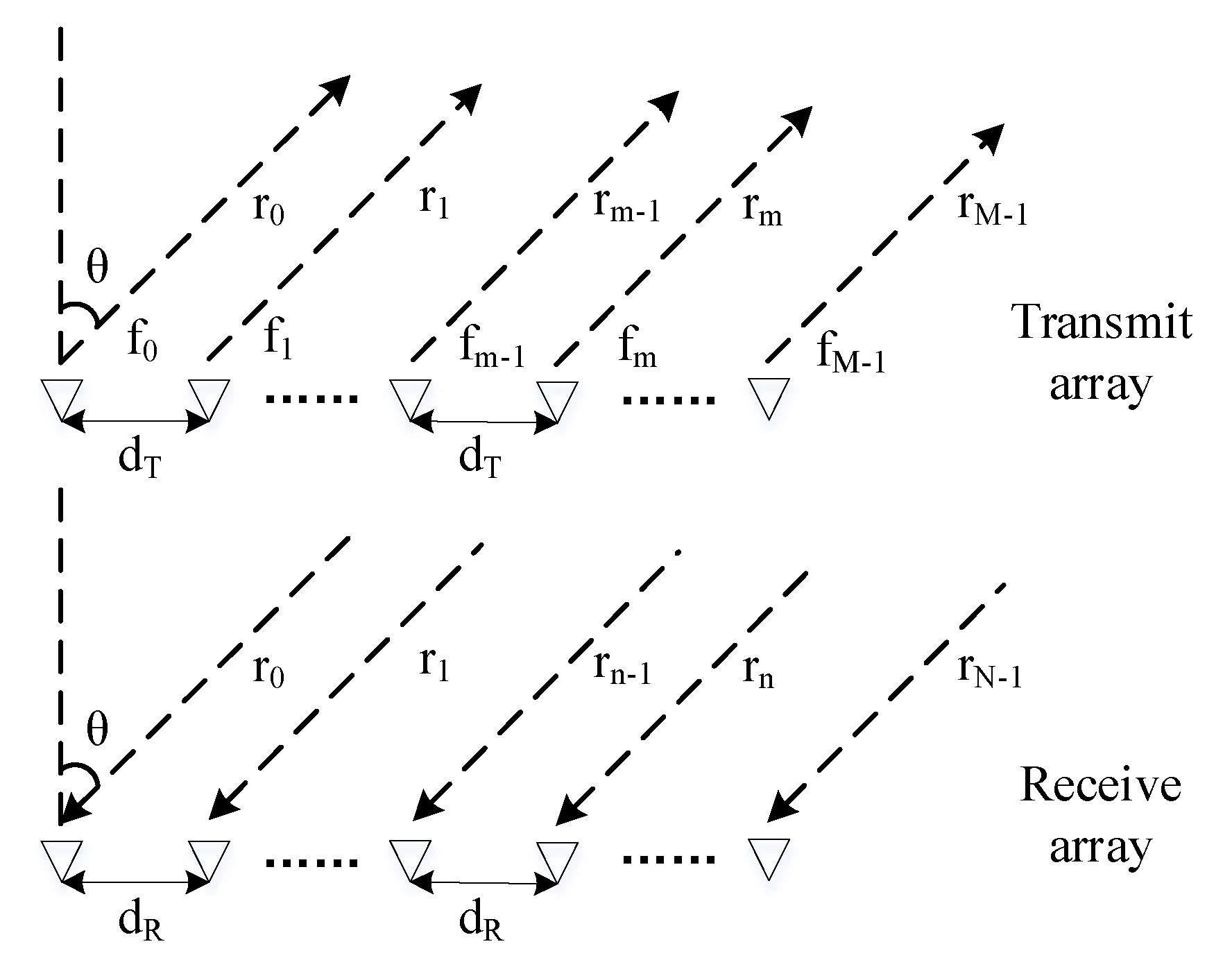
Consider an FDA-MIMO scheme whose structure is shown in Figure 1. The transmitting carrier frequency is , the interval between adjacent array elements of the transmitting array is , and the interval between adjacent array elements of the receiving array is , both of which are half-wavelength . The number of elements of the transmitting array and the number of elements of the receiving array are and , respectively. The transmitting frequency of the array element is
where is the frequency offset increment of the array element. Then the signal emitted by the array element can be expressed as
where is the complex envelope of the signal and is the pulse duration. The function can be defined as
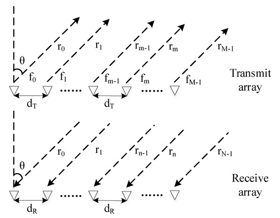
Figure 1.
The structure diagram of FDA-MIMO.
After the transmitting array element transmits the signal, the signal received by the receiving array element can be expressed as
where is the propagation delay from the transmitting array element to the receiving array element, which can be expressed as
It should be noted that the phase difference between the receiving array element and the reference array element cannot be neglected here, so Equation (4) can be expressed as
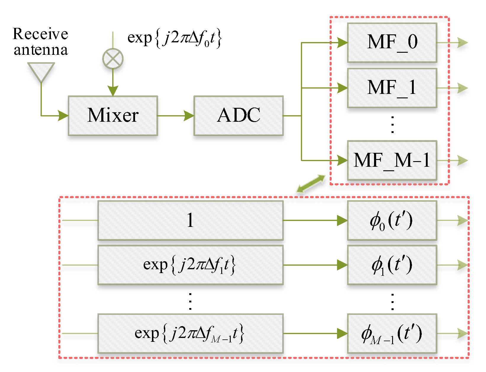
where is the time index within the pulse. Figure 2 shows the signal processing flow at the receiver side, where the signal is received by the receiving antenna, it is first mixed with the signal and the signal in the signal processor, and then matched filtering with the signal in the digital signal processing equipment.
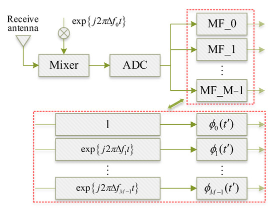
Figure 2.
Signal processing flow at the receiver side.
Then the output signal of the receiving array element related to the transmitting array element can be expressed as
where is the complex coefficient after matched filtering. After the matched filtering process, the signal at the output end is independent of the time parameter and is only related to the range parameter, so Equation (7) can also be expressed as
Thus, its array factor can be expressed as
Its steering vector can be expressed as
where is the Kronecker operator, and represents the transmit steering vector and the receive steering vector, which can be expressed as
The transmit–receive antenna pattern at the spatial target point can be expressed as
From Equation (13), it can be seen that by adopting the FDA-MIMO structure with multiple matched filters at the receiver side, the generated antenna pattern is range-dependent.
2.2. Jamming Model against FDA-MIMO
DRFM can realize the functions of storage, modulation, and forwarding of radio frequency signals. By modulating the received signal, it can cover the real target and even generate a large number of false target signals, forming an electronic countermeasure technology that integrates deception, suppression, and interference. The false target generated by DRFM can be expressed as
where is the jamming complex coefficient, and . Figure 3 shows the signal processing flow related to the range information at the receiving side of the FDA-MIMO radar.
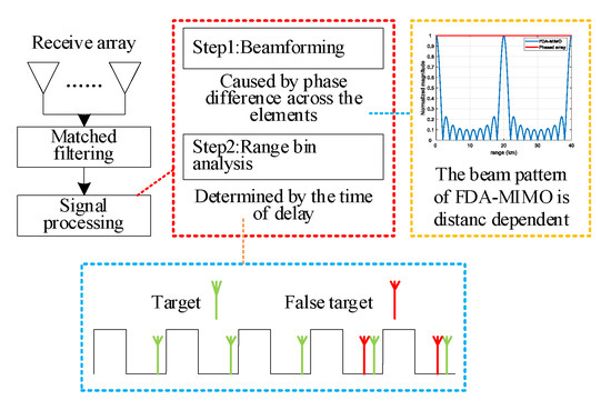
Figure 3.
The flow of signal processing related to range information at the FDA-MIMO receiver.
At the estimation level of the range bin, the range parameter is jointly determined by the time delay and the pulse repetition period , that is
where represents the remainder of and is the maximum unambiguous range. The array factor of the signal at the receiving side can be expressed as
Thus, its normalized antenna pattern can be expressed as
When the adaptive beamforming algorithm is used for processing, the normalized gain is
Without considering the time delay modulation, which is , there are
In Equations (18) and (19), the gain at the desired target is the maximum gain. The gain obtained at the side lobe position where the jamming is located is reduced, and its power will be greatly reduced, the interference performance is poor.
3. MVDR Adaptive Beamforming Algorithm
The MVDR adaptive beamforming algorithm adopts the sampling matrix inversion algorithm in adaptive beamforming, which minimizes the output power of the array in the desired direction by adding a weight coefficient at each array element, and it has a fast convergence speed under SINR.
The desired target signal in space is , the desired target position information is , the jamming signal is , the jamming position is , and the array element noise is . Then the array element signal at the receiving side is
Then the matrix form of the whole array is
where is the receiving steering vector from the direction of , which can be expressed as
The array output is
When interferences are known, to maximize the power of the beamforming output signal and accurately receive the desired signal in the direction, according to Equation (23), the constraint condition of the weight coefficient can be obtained as
This constraint causes the zero point of each beam pattern of the receive array to point to J interfering signals. To minimize the noise when the constraints of Equation (24) are satisfied at the same time, the objective function is optimized as
Then the MVDR weight optimization problem can be expressed as
The essence of the MVDR beamformer is to solve the weight coefficient of each array element. Then the Lagrange multiplier method can be used to obtain
After deriving Equation (27) and making it zero, we can obtain
Solving Equation (28), we can obtain
Expressing the constraint condition as and then multiplying both sides of Equation (29) by at the same time to obtain
Finally, the optimal value of the array weight is obtained according to the MVDR criterion as
where ,. The output SINR is
4. Jamming Methods and Models
The existing false target jamming methods cannot produce an effective jamming effect on FDA-MIMO radar. Therefore, this paper studies a suppression and range deceptive compound jamming method against FDA-MIMO. Firstly, the range dimension beamforming gain is analyzed in the spatial domain, and then an effective compound jamming effect is formed at the range bin estimation level for FDA-MIMO.
The spatial position of the jammer is , and the intercepted signal can be expressed as
where represents the propagation delay difference of the transmitting array element relative to the reference array element, and represents the reference propagation delay.
After receiving the radar signal, the receiver of the jammer first amplifies its power by a low-noise amplifier, then down-converts it, and finally passes it through a band-pass filter bank (the bandwidth of the filter bank is , and the center frequency is ), and its signal processing flow is shown in Figure 4. Then the output signal of the filter output can be expressed as
where , represents the common phase change term related to .
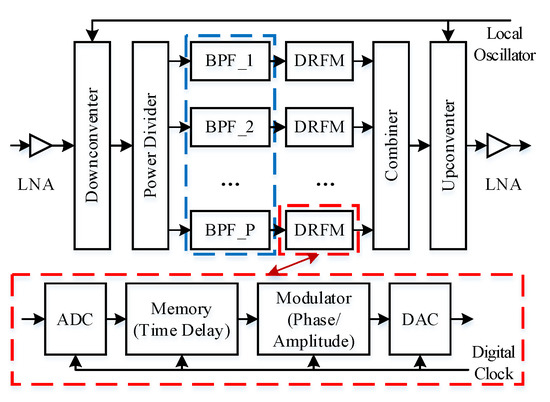
Figure 4.
The signal processing flow of the jamming model.
The signal is filtered by the band-pass filter bank, and then modulated by the time delay and the phase , the obtained false target signal can be expressed as
where is the amplitude, represents the common phase change term, and . The false target signal is mixed with the local oscillator signal , and then upconverting it, the final signal can be expressed as
where is the common term after up-conversion. The signal at the receiver side of the receiver array can be expressed as
where represents the propagation time delay difference between the received array element and the reference array element. The Equation (37) can be approximately expressed as
where represents the intra-pulse time index in this case. In the signal processing process at the receiving side, the received signal is mixed with the signal and the signal , and then matched filtering with the signal . The final signal can be expressed as
where represents the complex coefficient after signal matching filtering, and . Considering a self-defense jammer at the position , the weight vector of the target can be set as
So, its normalized antenna pattern can be expressed as
After jamming forwarding, the resulting jamming signal weight vector can be expressed as
Then its normalized beam gain can be expressed as
From Equation (43), it can be seen that the jamming signal can obtain the same maximum beam gain as the desired target, and its power was not significantly reduced at the beamforming level, thus it can form an effective jamming effect against FDA-MIMO. By adjusting the time delay, the jamming signal can appear at different range bins, thus forming an effective compound jamming effect, which can affect the normal detection and positioning of the radar.
5. Simulation Analysis
In this section, the proposed compound jamming method is validated. The existing fake targets were named as existing fake target (EFT) and labeled as EFT1 and EFT2, and the newly generated fake targets were named as new fake target (NFT) and labeled as NFT1 and NFT2. The number of transmitting array elements was , and the number of receiving array elements was , the reference carrier frequency was , the wavelength was , and the position information of the desired target was . The parameters were set as shown in Table 1.

Table 1.
Simulation parameters setting table.
5.1. Beamforming Gain Analysis
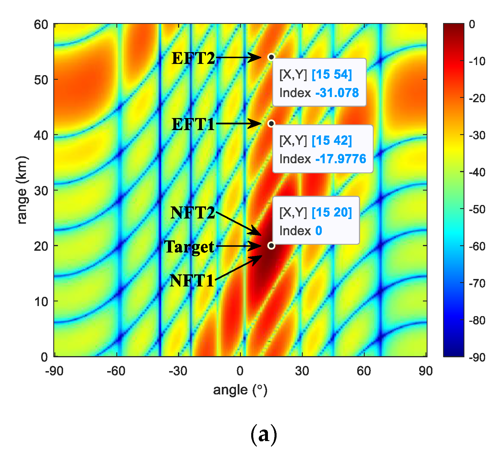
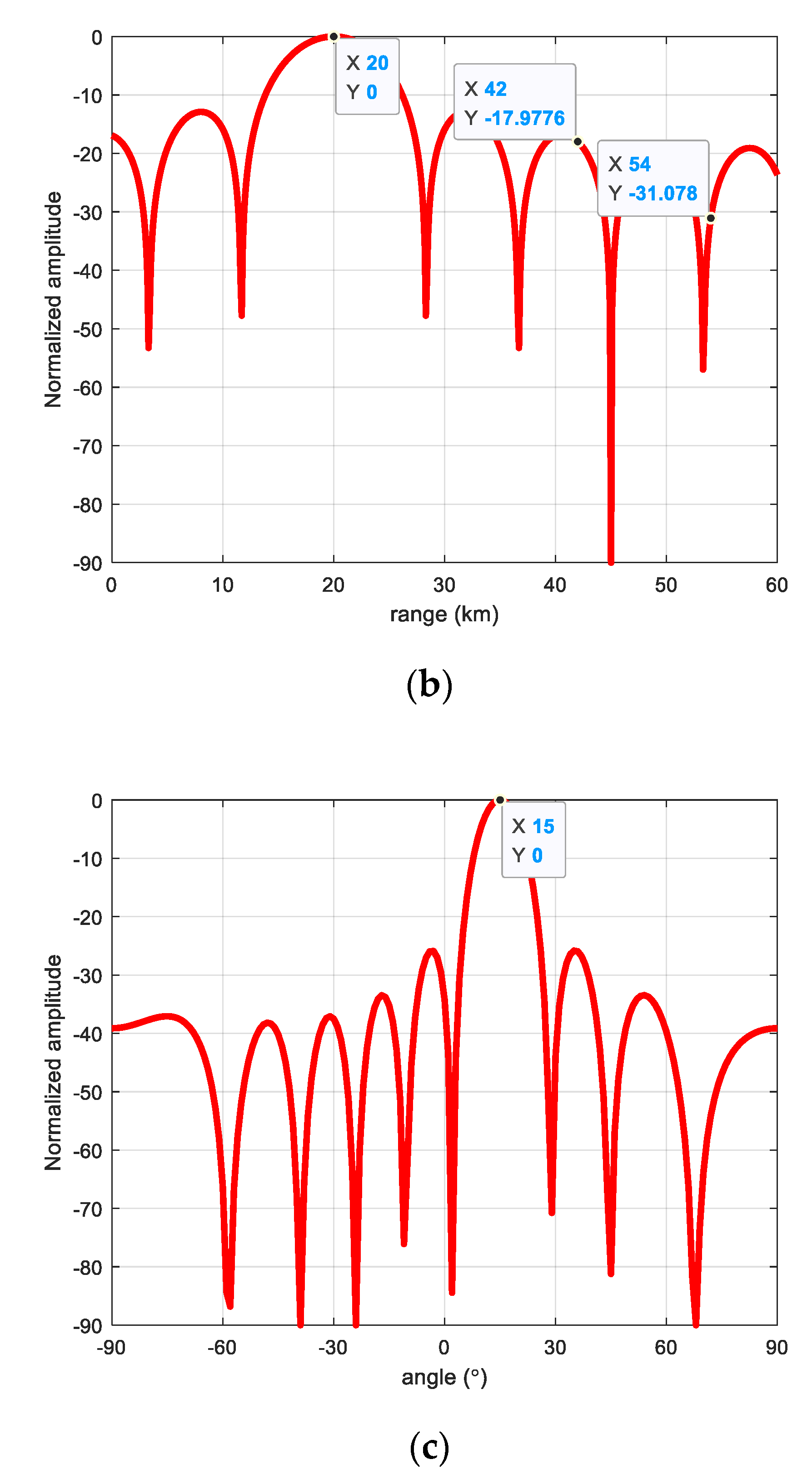
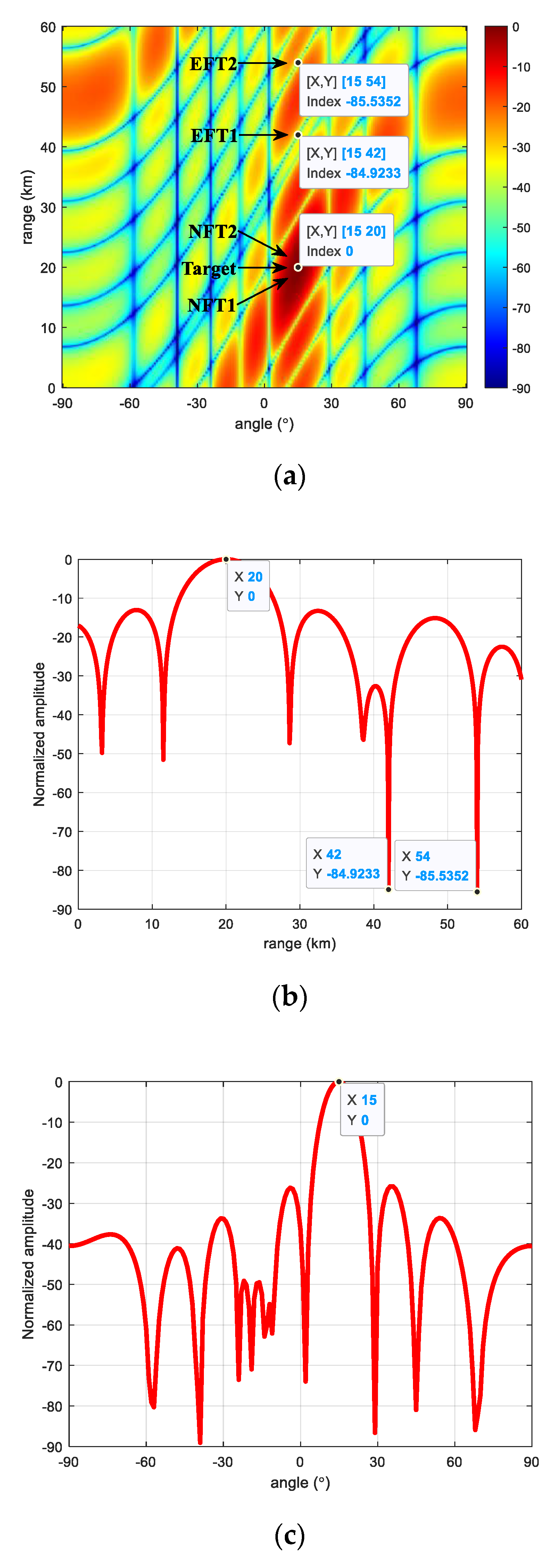
Figure 5 is the FDA-MIMO non-adaptive beam antenna pattern. As can be seen from Figure 5, the desired target and the false target NFT1 and NFT2 were located at the peak position of the antenna pattern, and the false target can obtain the same gain as the desired target. The false targets EFT1 and EFT2 were located at the side lobe positions, and the gain at their positions was low, so the power at the false targets EFT1 and EFT2 will be greatly weakened after passing through the radar system. At the same angle, observed from the range dimension profile, the gain at the position of the false target EFT was reduced compared to that of the desired target, but it still had a higher beam gain. At the same range, observed from the angle dimension profile, the false target and the desired target had the same large angle dimension beam gain.
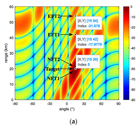
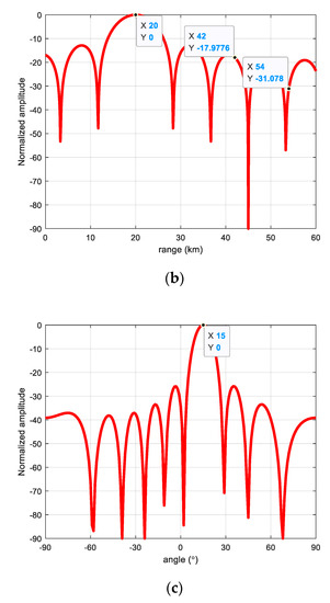
Figure 5.
FDA-MIMO non-adaptive beamforming gain. (a) Range-angle two-dimensional beamforming gain; (b) Range dimension; (c) Angle dimension.
Figure 6 is the FDA-MIMO range-angle two-dimensional MVDR adaptive beam antenna pattern. As can be seen from Figure 6, the gain at the desired target was almost unchanged compared to the non-adaptive beam gain, and the false targets NFT1 and NFT2 were still at the peak position of the antenna pattern, which can obtain a higher beam gain as the desired target. The false targets EFT1 and EFT2 were located at the side lobe position of the range dimension, and their gain was significantly reduced compared to the non-adaptive beam. At the same angle, observed from the range dimension profile, the gain at the position of the false target EFT was greatly reduced compared to the gain at the desired target, and it formed a zero notch in the range dimension side lobes. At the same range, observed from the angle dimension profile, the false target also had the same angle dimension beam gain as the desired target, similar to the non-adaptive beam.

Figure 6.
FDA-MIMO range-angle two-dimensional MVDR adaptive beamforming gain. (a) Range-angle two-dimensional beamforming gain; (b) Range dimension; (c) Angle dimension.
Table 2 shows the values of the gain for the non-adaptive beam and the range-angle two-dimensional MVDR adaptive beam. As can be seen from Table 2, the gain values at the desired target and the false targets NFT1 and NFT2 under non-adaptive beamforming reached the maximum gain values, while the beam gain values at the false targets EFT1 and EFT2 were reduced by 20 dB. With the range-angle two-dimensional MVDR adaptive beamforming algorithm, the gain of the desired target and the false targets NFT1 and NFT2 remained almost unchanged, while the beam gains at the false targets EFT1 and EFT2 were reduced to −80 dB, and they could no longer form an effective jamming effect.
Table 2.
Gain comparison table.
5.2. Range Bin Analysis Results
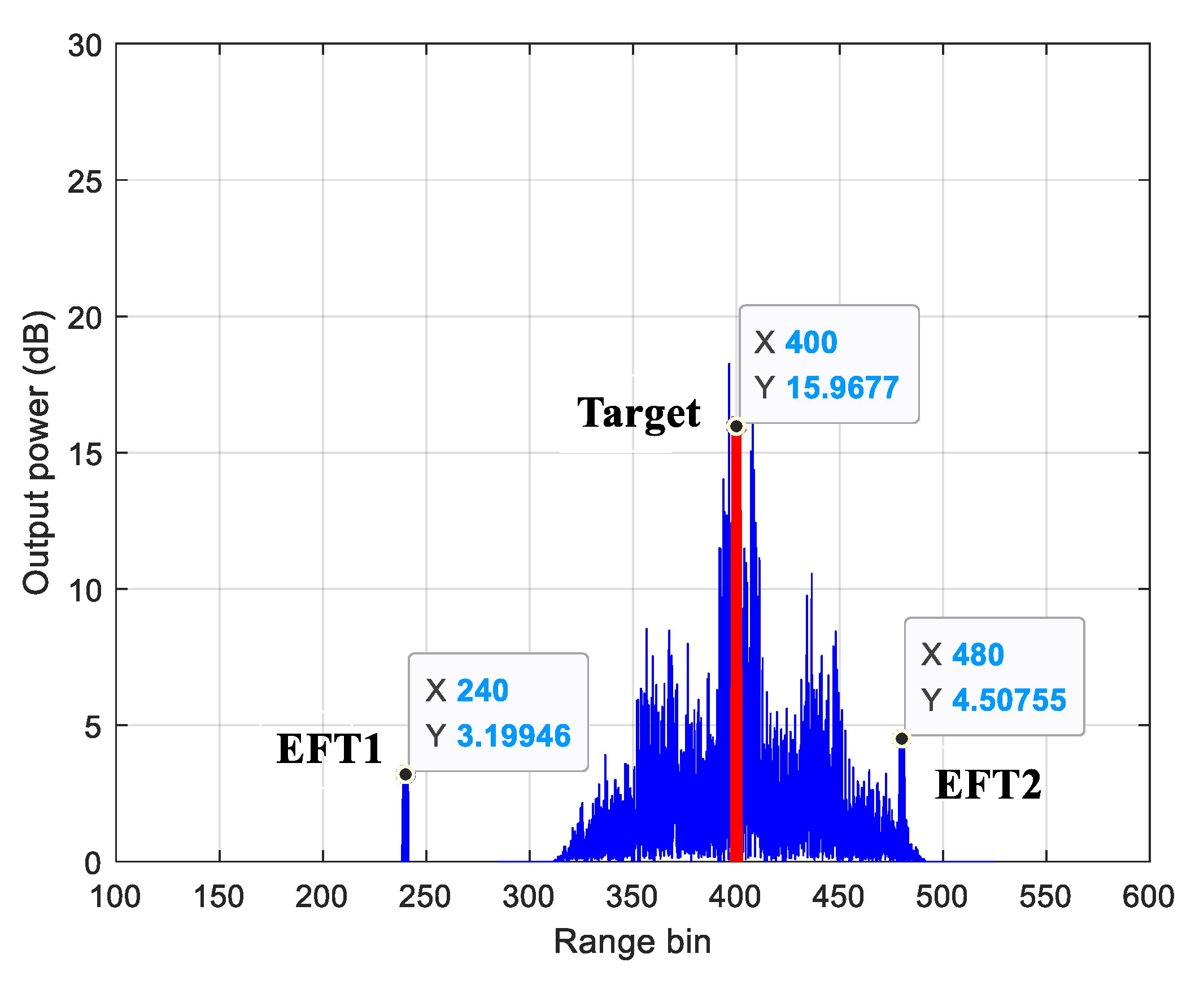
Figure 7 shows the range bin analysis results of the false targets EFT1 and EFT2 and the suppression jamming under non-adaptive beamforming. As can be seen from Figure 7, the output power of the false targets EFT1 and EFT2 was significantly lower than that of the desired target, and their jamming effect was poor and failed to form an effective jamming effect.
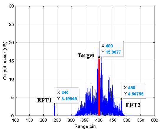
Figure 7.
Analysis results of existing jamming range bin under non-adaptive beamforming.
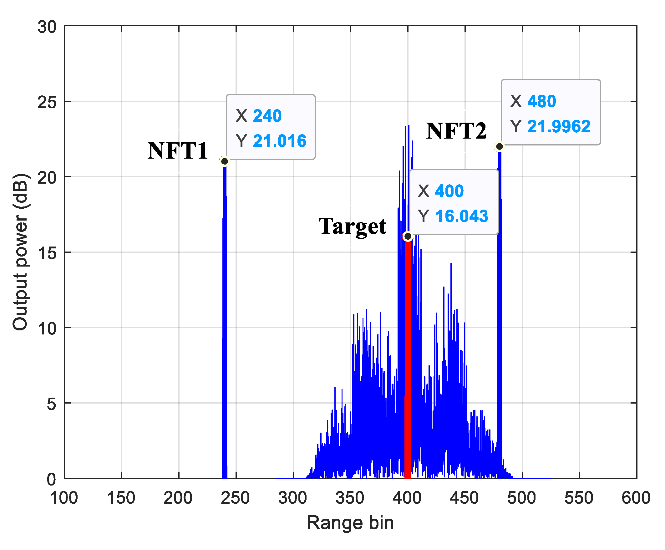
Figure 8 shows the range bin analysis results of the false targets NFT1 and NFT2 and the suppression jamming under non-adaptive beamforming. As can be seen from Figure 8, the false targets NFT1 and NFT2 had high output power as well as the desired target, and at this time the suppression jamming completely covered the desired target, which could form an effective suppression and range deceptive compound jamming effect, and the jamming effect was good, which could effectively interfere with the normal detection and positioning of radar.
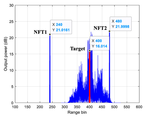
Figure 8.
Analysis results of new jamming range bin under non-adaptive beamforming.
Figure 9 shows the range bin analysis results of the false targets EFT1 and EFT2 and the suppression jamming under range-angle two-dimensional MVDR adaptive beamforming. As can be seen from Figure 9, the output power of the false targets EFT1 and EFT2 was severely suppressed, and their power was the same as the power of noise; therefore, it could not form an effective jamming effect.
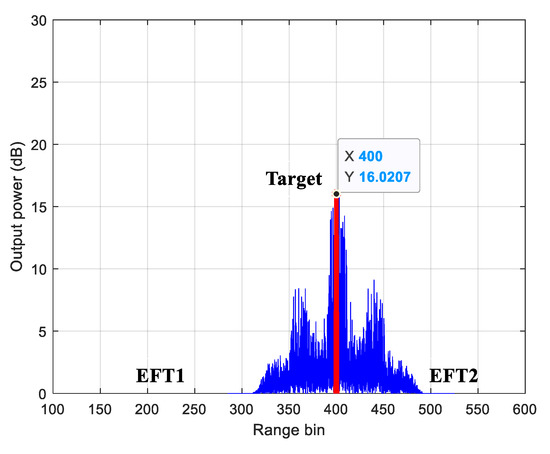
Figure 9.
Analysis results of existing jamming range bin under range-angle two-dimensional MVDR adaptive beamforming.
Figure 10 shows the range bin analysis results of the false targets NFT1 and NFT2 and the suppression jamming under range-angle two-dimensional MVDR adaptive beamforming. As can be seen from Figure 10, the output power of the false targets NFT1 and NFT2 was high, and at this time the suppression jamming completely covered the desired target, and it was little affected by the MVDR adaptive beam, which could form an effective suppression and range deceptive compound jamming effect, and the jamming effect was good.
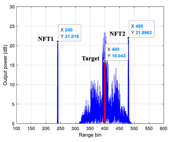
Figure 10.
Analysis results of new jamming range bin under range-angle two-dimensional MVDR adaptive beamforming.
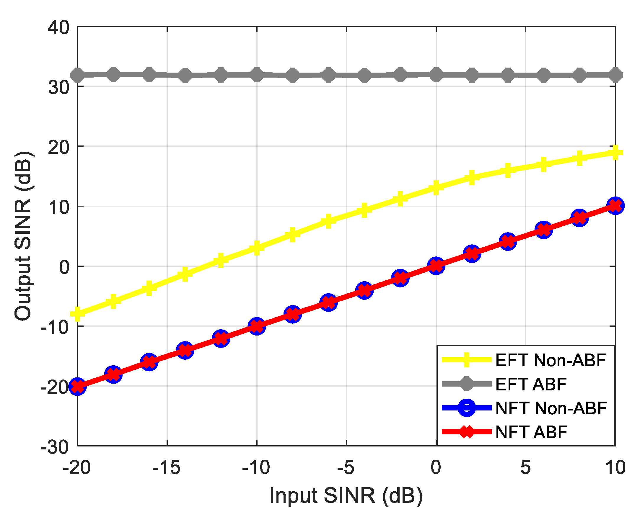
Figure 11 shows the output SINR performance comparison results of the proposed compound jamming and the existing jamming. As can be seen from Figure 11, under the non-adaptive beam, the output SINR of the existing jamming EFT varied with the input SINR. When the input SINR increased to a certain extent, the output SINR of the EFT gradually tended to be stable. Under the adaptive beam, the output SINR of the existing jamming EFT was maintained as relatively stable at a large value, and its jamming effect was weakened. Both under the non-adaptive beam and the adaptive beam, the compound jamming method proposed in this paper can keep the output SINR at a low level all the time, and thus the detection performance of the radar is reduced. The performance of the proposed compound jamming method was significantly better than the existing jamming methods.
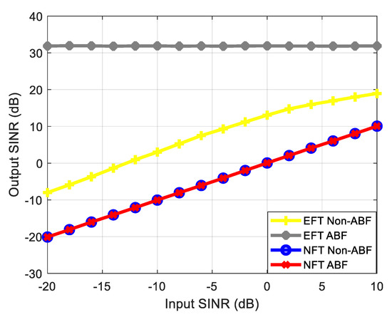
Figure 11.
The output SINR performance comparison of jamming technology.
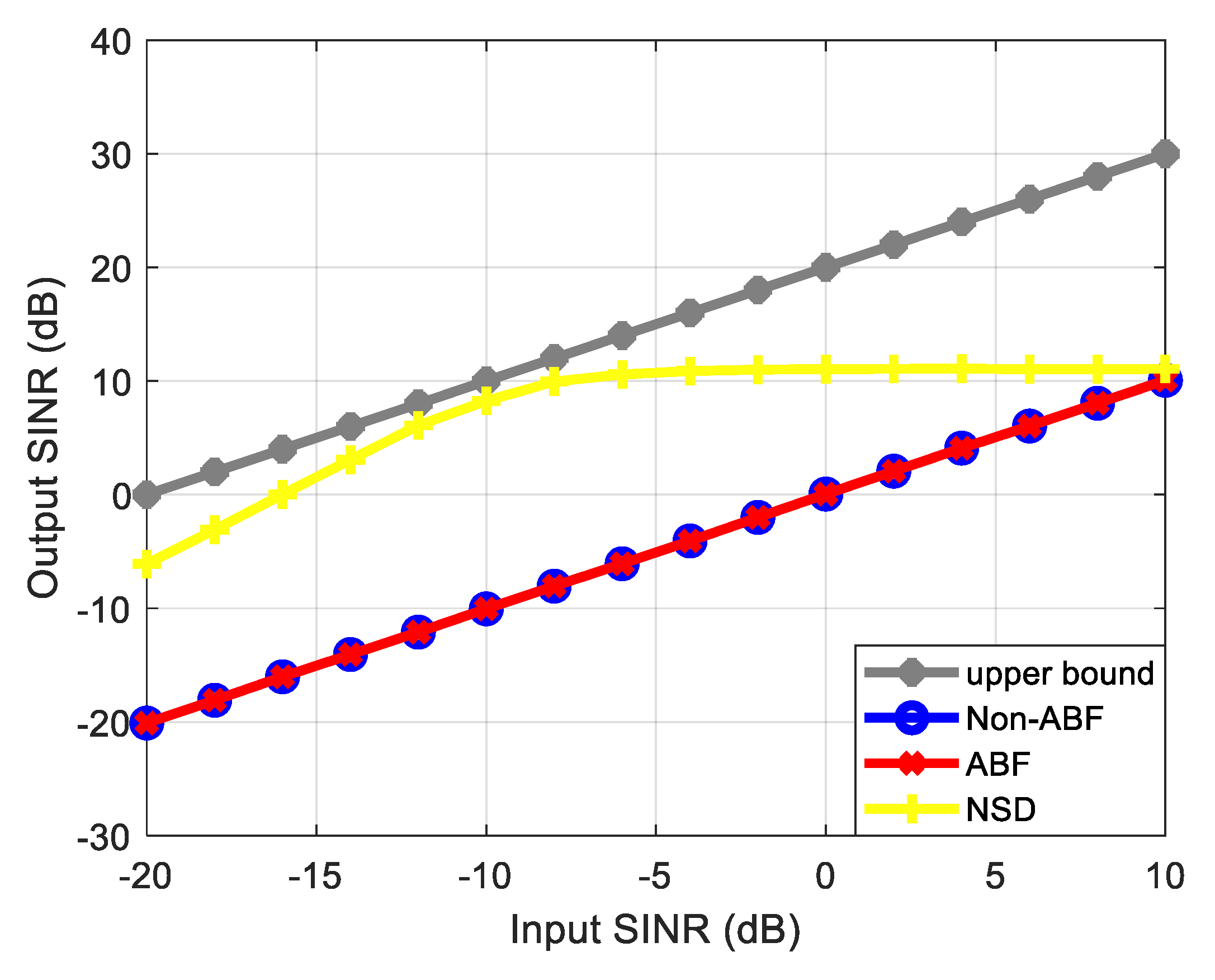
Figure 12 shows the output SINR performance comparison results of NFT under several anti-jamming technologies. As can be seen from Figure 12, under the non-adaptive beam and adaptive beam anti-jamming techniques, the output SINR of the proposed compound jamming method was lower. The output SINR of the adaptive NSD method tended to be smooth with the increase in the input SINR. The output SINR of all the anti-jamming methods was kept at a low level, and the proposed compound jamming method could produce significant jamming effects.
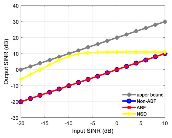
Figure 12.
The output SINR performance of NFT under anti-jamming technology.
6. Conclusions
This paper studied the jamming method against the FDA-MIMO beamforming level, and the main conclusions are as follows:
- (1)
- By studying the FDA-MIMO deceptive jamming model, an effective jamming method against FDA-MIMO radar was analyzed;
- (2)
- A suppression and range deceptive compound jamming method against FDA-MIMO beamforming was proposed. The beamforming gain and range bin estimation level were simulated and analyzed. Compared with the existing deceptive jamming methods, the proposed jamming method can obtain the same beam gain as the target, and it can produce a significant compound jamming effect for the range parameter estimation performance of FDA-MIMO radar;
- (3)
- The simulation results showed that the output SINR of the proposed jamming increased more slowly, and when the input SINR was 10 dB, the output SINR was also about 10dB, and the output SINR could always be kept at a low level, so the proposed jamming method can produce an effective compound jamming effect, and the jamming effect was good.
The jamming method studied in this paper for the frequency diverse array system radar also had a certain reference value for the jamming of new system radars and also provided a guiding meaning for the application and improvement of frequency diverse array system radar in complex electromagnetic environments. Future work could be carried out from the adaptive cognitive jamming technology.
Author Contributions
Conceptualization, Y.C. and B.T.; methodology, Y.C. and Y.Z.; software, Y.C. and J.G.; validation, Y.C. and B.T.; data curation, Y.C. and C.W.; writing—original draft preparation, Y.C.; writing—review and editing, Y.C. and B.T.; Supervision, C.W.; funding acquisition, J.G. All authors have read and agreed to the published version of the manuscript.
Funding
This work was supported by the Natural Science Foundation of Shaanxi Province under grant 2021JM-222 and the China Postdoctoral Science Foundation under grant 2019M662257.
Institutional Review Board Statement
Not applicable.
Informed Consent Statement
Not applicable.
Data Availability Statement
Not applicable.
Conflicts of Interest
The authors declare no conflict of interest.
References
- Antonik, P.; Wicks, M.C.; Griffiths, H.D.; Baker, C.J. Frequency diverse array radars. In Proceedings of the 2006 IEEE Conference on Radar, Verona, NY, USA, 24–27 April 2006. [Google Scholar]
- Wang, W.Q. Range-Angle Dependent Transmit Beampattern Synthesis for Linear Frequency Diverse Arrays. IEEE Trans. Antennas Propag. 2013, 61, 4073–4081. [Google Scholar] [CrossRef]
- Xu, J.W.; Zhu, S.Q.; Liao, G.S.; Zhang, Y.H. An Overview of Frequency Diverse Array Radar Technology. J. Radars 2018, 7, 167–182. [Google Scholar]
- Wang, W.Q.; Chen, H.; Zheng, Z.; Zhang, S.S. Advances on Frequency Diverse Array Radar and Its Applications. J. Radars 2018, 7, 153–166. [Google Scholar]
- Lan, L.; Xu, J.W.; Zhu, S.Q.; Liao, G.S.; Zhang, Y.H. Advances in anti-jamming using waveform diverse array radar. Syst. Eng. Electron. 2021, 43, 1437–1451. [Google Scholar]
- Sammartino, P.F.; Baker, C.J.; Griffiths, H.D. Frequency Diverse MIMO Techniques for Radar. IEEE Trans. Aerosp. Electron. Syst. 2013, 49, 201–222. [Google Scholar] [CrossRef]
- Xu, J.W.; Liao, G.S.; Zhu, S.Q.; Huang, L.; So, H.C. Joint Range and Angle Estimation Using MIMO Radar With Frequency Diverse Array. IEEE Trans. Signal Process. 2015, 63, 3396–3410. [Google Scholar] [CrossRef]
- Wang, W.Q. Overview of frequency diverse array in radar and navigation applications. IET Radar Sonar Navig. 2016, 10, 1001–1012. [Google Scholar] [CrossRef]
- Zhu, S.Q.; Yu, K.; Xu, J.W.; Lan, L.; Li, X.M. Research Progress and Prospect for the Noval Waveform Diverse Array Radar. J. Radars 2021, 10, 795–810. [Google Scholar]
- Wan, P.F.; Weng, Y.L.; Xu, J.W.; Liao, G.S. Range Gate Pull-Off Mainlobe Jamming Suppression Approach with FDA-MIMO Radar: Theoretical Formalism and Numerical Study. Remote Sens. 2022, 14, 1499. [Google Scholar] [CrossRef]
- Huang, L.B.; Zong, Z.L.; Zhang, S.S.; Wang, W.Q. 2-D Moving Target Deception Against Multichannel SAR-GMTI Using Frequency Diverse Array. IEEE Geosci. Remote Sens. Lett. 2022, 19, 1–5. [Google Scholar] [CrossRef]
- Liu, W.J.; Liu, J.; Hao, C.P.; Gao, Y.C.; Wang, Y.L. Multichannel adaptive signal detection: Basic theory and literature review. Sci. China Inf. Sci. 2022, 65, 5–44. [Google Scholar] [CrossRef]
- Chen, H.; Liu, Y.N.; Lv, M.J.; Zhang, X.W.; Xia, B.; Xie, D. Networked FDA-MIMO radar positioning to suppress dense false target jamming. J. Phys. Conf. Ser. 2021, 1920, 012061. [Google Scholar] [CrossRef]
- Ding, Z.H.; Xie, J.W.; Wang, B.; Zhang, H.W. Robust Adaptive Null Broadening Method Based on FDA-MIMO Radar. IEEE Access 2020, 8, 177976–177983. [Google Scholar] [CrossRef]
- Zhou, C.L.; Wang, C.Y.; Gong, J.; Tan, M.; Zhao, Y.J.; Liu, M.J. FDA-MIMO Beampattern Synthesis with an Analytical Method. Int. J. Aerosp. Eng. 2021, 2021, 1–11. [Google Scholar] [CrossRef]
- Xu, J.W.; Liao, G.S.; Zhu, S.Q.; So, H.C. Deceptive jamming suppression with frequency diverse MIMO radar. Signal Process. 2015, 113, 9–17. [Google Scholar] [CrossRef]
- Wen, C.; Peng, J.Y.; Zhou, Y.; Wu, J.X. Enhanced Three-Dimensional Joint Domain Localized STAP for Airborne FDA-MIMO Radar Under Dense False-Target Jamming Scenario. IEEE Sens. J. 2018, 18, 4154–4166. [Google Scholar] [CrossRef]
- Shi, J.T.; Liu, X.; Yang, Y.H.; Sun, J.; Wang, N. Comments on “Deceptive jamming suppression with frequency diverse MIMO radar”. Signal Process. 2019, 158, 1–3. [Google Scholar] [CrossRef]
- Wang, B.; Xie, J.W.; Ge, J.A.; Zhang, J. Angle deception effect of FDA on amplitude comparison direction finding system with single pulse. J. Beijing Univ. Aeronaut. Astronaut. 2020, 46, 643–650. [Google Scholar]
- Tan, M.; Wang, C.Y.; Xue, B.; Xu, J.W. A Novel Deceptive Jamming Approach Against Frequency Diverse Array Radar. IEEE Sens. J. 2021, 21, 8323–8332. [Google Scholar] [CrossRef]
- Zhao, Y.J.; Tian, B.; Wang, C.Y.; Gong, J.; Tan, M.; Zhou, C.L. Research on main-lobe deceptive jamming against FDA-MIMO radar. IET Radar Sonar Navig. 2021, 15, 641–654. [Google Scholar] [CrossRef]
- Shahid, M.; Aqdas, N.M.; Ijaz, M.Q.; Muhammad, Z.U.K.; Fawad, Z. A Novel Deceptive Jamming Approach for Hiding Actual Target and Generating False Targets. Wirel. Commun. Mob. Comput. 2021, 2021, 1–20. [Google Scholar]
- Zhao, Y.J.; Tian, B.; Wang, C.Y.; Gong, J.; Tan, M. Robust adaptive beamforming via improved worst-case performance optimization algorithm based on FDA-MIMO. Multidimens. Syst. Signal Process. 2022, 33, 725–746. [Google Scholar] [CrossRef]
- Lan, L.; Liao, G.S.; Xu, J.W.; Zhu, S.Q.; Zhang, Y.H. Range-angle-dependent beamforming for FDA-MIMO radar using oblique projection. Sci. China Inf. Sci. 2022, 65, 223–241. [Google Scholar] [CrossRef]
- Sun, Q.Y.; Shu, T.; Yu, K.B.; Yu, W.X. Efficient Deceptive Jamming Method of Static and Moving Targets Against SAR. IEEE Sens. J. 2018, 18, 3610–3618. [Google Scholar] [CrossRef]
- Gui, R.H.; Huang, B.; Wang, W.Q.; Sun, Y. Generalized Ambiguity Function for FDA Radar Joint Range, Angle and Doppler Resolution Evaluation. IEEE Geosci. Remote Sens. Lett. 2022, 19, 1–5. [Google Scholar] [CrossRef]
- Huang, L.B.; Li, X.; Wan, W.T.; Zhang, S.S.; Wang, W.Q. Frequency Diverse Array Introduced Into SAR GMTI to Mitigate Blind Velocity and Doppler Ambiguity. IEEE Geosci. Remote Sens. Lett. 2022, 19, 1–5. [Google Scholar] [CrossRef]
- Huang, B.; Wang, W.Q.; Zhang, S.S.; Wang, H.; Gui, R.H.; Lu, Z. A Novel Approach for Spaceborne SAR Scattered-Wave Deception Jamming Using Frequency Diverse Array. IEEE Geosci. Remote Sens. Lett. 2020, 17, 1568–1572. [Google Scholar] [CrossRef]
- Huang, B.; Wang, W.Q.; Zhang, S.S.; Liao, Y. FDA-Based Space-Time–Frequency Deceptive Jamming Against SAR Imaging. IEEE Trans. Aerosp. Electron. Syst. 2022, 58, 2127–2140. [Google Scholar]
- Huang, L.B.; Zong, Z.L.; Zhang, S.S.; Wang, W.Q. Joint Two-Dimensional Deception Countering ISAR via Frequency Diverse Array. IEEE Signal Process Lett. 2021, 28, 773–777. [Google Scholar] [CrossRef]
- Zhang, Z.J.; Xie, J.W.; Li, X.; Sheng, C.; Hu, Q.Y. Discrimination method of range deception jamming based on FDA-MIMO. J. Beijing Univ. Aeronaut. Astronaut. 2017, 43, 738–746. [Google Scholar]
- Wan, F.H.; Xu, J.W.; Zhang, Z.R. Robust Beamforming Based on Covariance Matrix Reconstruction in FDA-MIMO Radar to Suppress Deceptive Jamming. Sensors 2022, 22, 1479. [Google Scholar] [CrossRef]
- Lan, L.; Liao, G.S.; Xu, J.W.; Zhang, Y.H.; Fioranelli, F. Suppression Approach to Main-Beam Deceptive Jamming in FDA-MIMO Radar Using Nonhomogeneous Sample Detection. IEEE Access. 2018, 6, 34582–34597. [Google Scholar] [CrossRef]
- Xu, J.W.; Liao, G.S.; Zhang, Y.H.; So, H.C. On Anti-jamming Technique with Waveform Diverse Array Radar. Acta Electron. Sin. 2019, 47, 545–551. [Google Scholar]
- Wang, Y.Z.; Zhu, S.Q. Main-Beam Range Deceptive Jamming Suppression with Simulated Annealing FDA-MIMO Radar. IEEE Sens. J. 2020, 20, 9056–9070. [Google Scholar] [CrossRef]
- Liao, Y.; Tang, H.; Chen, X.L.; Wang, W.Q.; Xing, M.D.; Zheng, Z.; Wang, J.; Liu, Q.H. Antenna Beampattern with Range Null Control Using Weighted Frequency Diverse Array. IEEE Access. 2020, 8, 50107–50117. [Google Scholar] [CrossRef]
- Zhang, X.J.; He, Z.S.; Liao, B.; Zhang, X.P.; Peng, W.W. Robust quasi-adaptive beamforming against direction-of-arrival mismatch. IEEE Trans. Aerosp. Electron. Syst. 2018, 54, 1197–1207. [Google Scholar] [CrossRef]
- Zhuang, J.; Xue, Y.S.; Kang, J.C.; Chen, D.L.; Wan, Q. Robust adaptive beamforming under data dependent constraints. Signal Process. 2021, 188, 108202. [Google Scholar] [CrossRef]
- Yao, D.; Zhang, X.; Hu, B.; Yang, Q.; Wu, X.C. Robust Adaptive Beamforming with Optimal Covariance Matrix Estimation in the Presence of Gain-Phase Errors. Sensors 2020, 20, 2930. [Google Scholar] [CrossRef] [PubMed]
- Liu, Y.B.; Wang, C.Y.; Gong, J.; Tan, M.; Chen, G. Robust Suppression of Deceptive Jamming with VHF-FDA-MIMO Radar under Multipath Effects. Remote Sens. 2022, 14, 942. [Google Scholar] [CrossRef]
- Ge, J.A.; Xie, J.W.; Wang, B. A Cognitive Active Anti-jamming Method Based on Frequency Diverse Array Radar Phase Center. Digit. Signal Process. 2021, 109, 102915. [Google Scholar] [CrossRef]


Publisher’s Note: MDPI stays neutral with regard to jurisdictional claims in published maps and institutional affiliations. |
© 2022 by the authors. Licensee MDPI, Basel, Switzerland. This article is an open access article distributed under the terms and conditions of the Creative Commons Attribution (CC BY) license (https://creativecommons.org/licenses/by/4.0/).