
Erosion Resistant Hydrophobic Coatings for Passive Ice Protection of Aircraft


Abstract
:1. Introduction
2. Materials and Methods
2.1. Materials
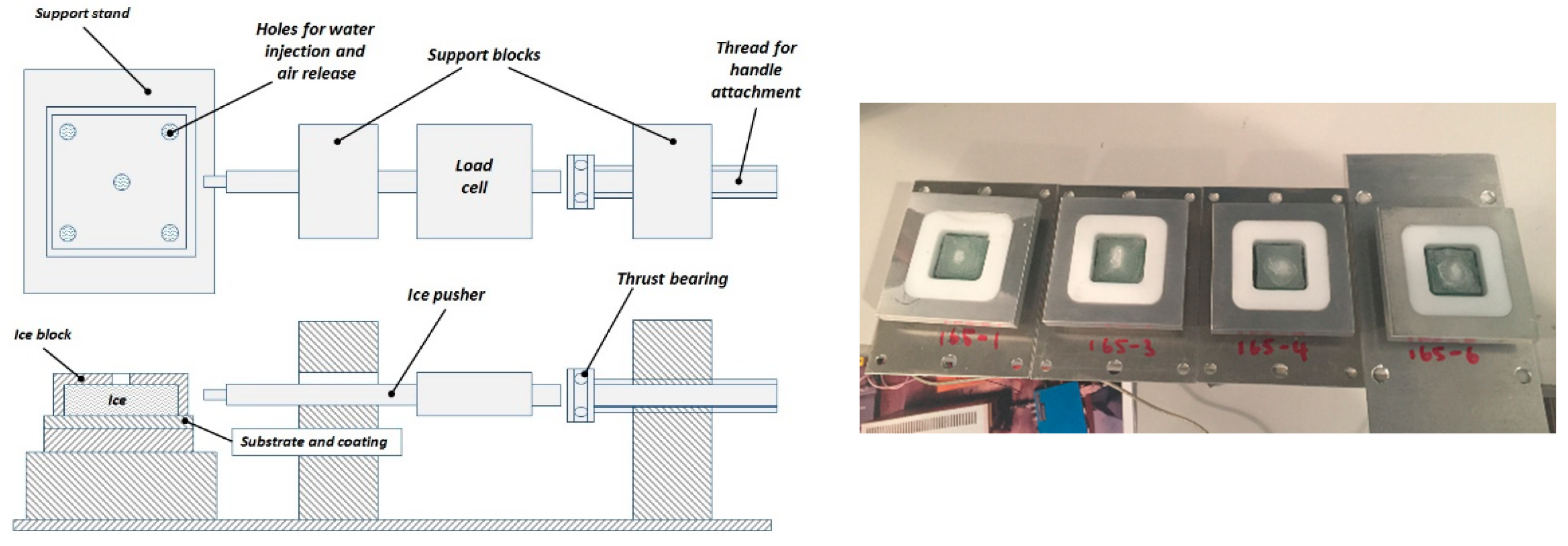
2.2. Methods
2.3. Preparation of Surface-Modifying Polymers (SMPs) and Durable Hydrophobic Polyurethane (SPU) Coatings
3. Results and Discussion
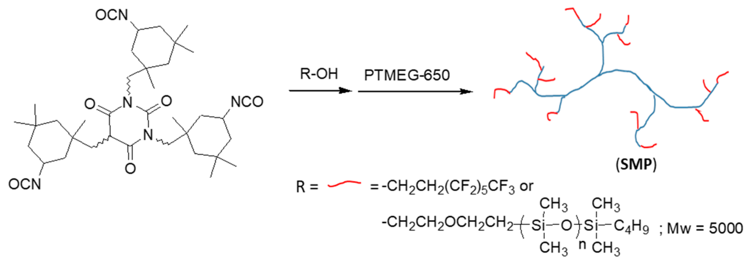
3.1. Synthesis of SMPs and SPU Coatings
3.2. Coating Formulation and Preparation
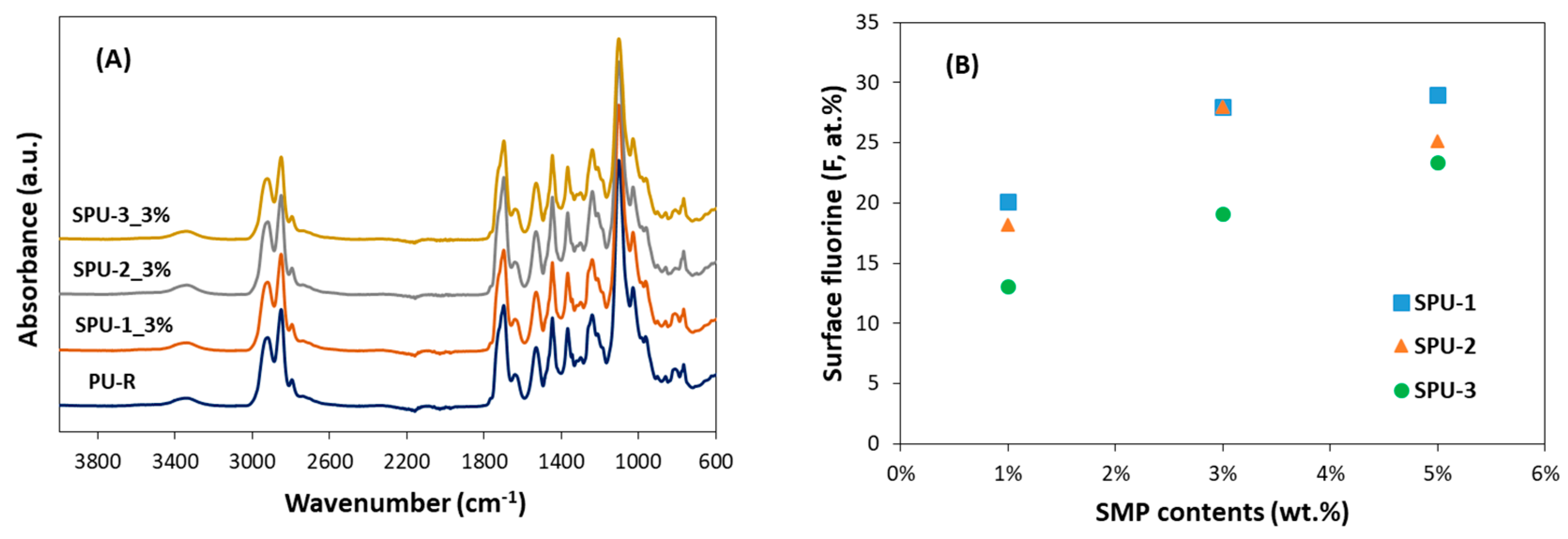
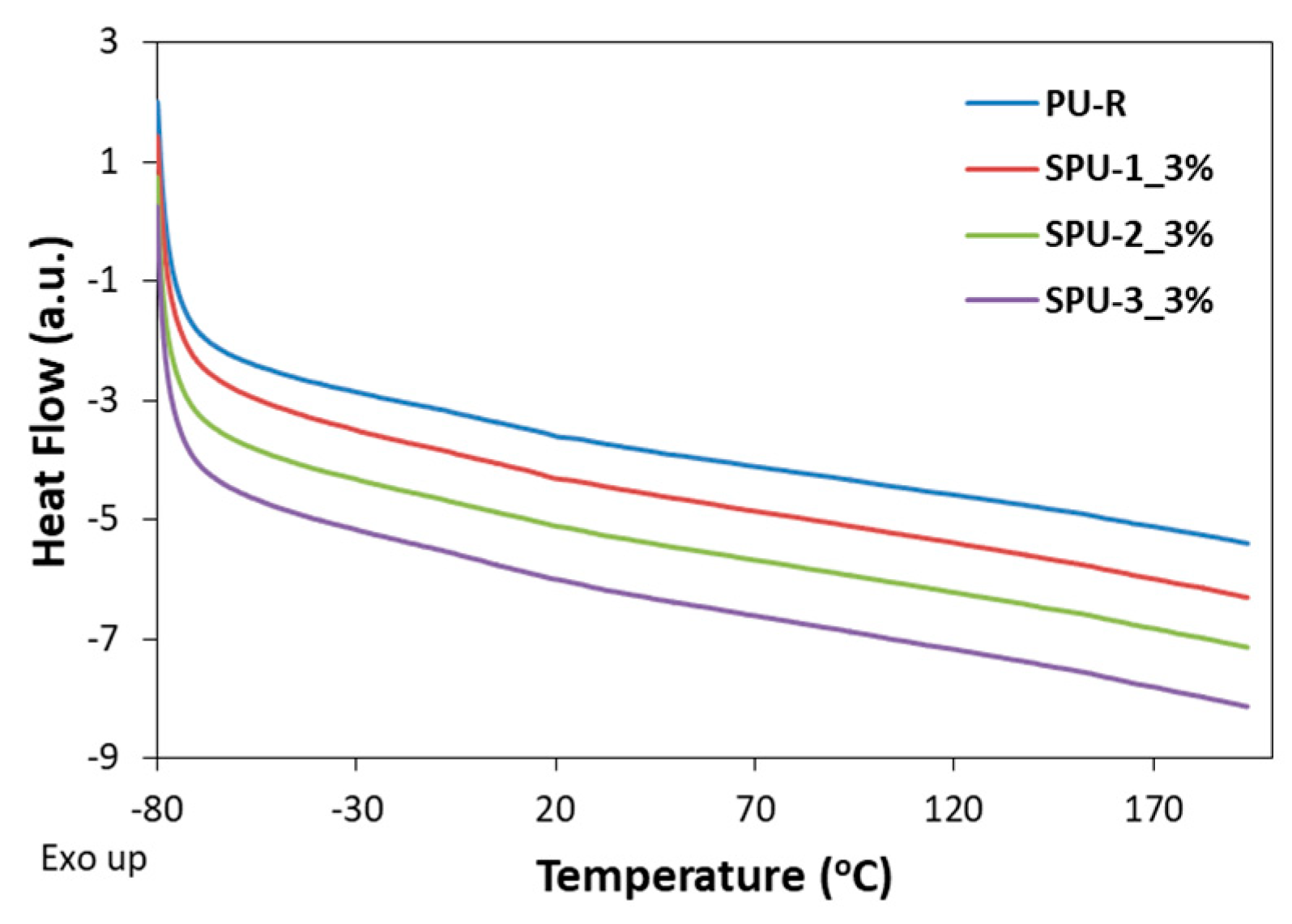
3.3. Properties of SPU Coatings
4. Conclusions
Author Contributions
Funding
Institutional Review Board Statement
Informed Consent Statement
Data Availability Statement
Conflicts of Interest
References
- Yamazaki, M.; Jemcov, A.; Sakaue, H. A Review on the Current Status of Icing Physics and Mitigation in Aviation. Aerospace 2021, 8, 188. [Google Scholar] [CrossRef]
- Federal Aviation Administration. Aircraft Icing Handbook; U.S. Department of Transportation: Washington, DC, USA, 1991; Volume 1.
- Federal Aviation Administration. AC 91-74B Pilot Guide: Fight in Icing Conditions; U.S. Department of Transportation: Washington, DC, USA, 2015.
- Federal Aviation Administration. Aircraft Icing Handbook; U.S. Department of Transportation: Washington, DC, USA, 1991; Volume 2.
- Huang, X.; Tepylo, N.; Pommier-Budinger, V.; Budinger, M.; Bonaccurso, E.; Villedieu, P.; Bennani, L. A survey of icephobic coatings and their potential use in a hybrid coating/active ice protection system for aerospace applications. Prog. Aerosp. Sci. 2019, 105, 74–97. [Google Scholar] [CrossRef]
- He, Z.; Zhuao, Y.; Zhang, Z.; He, J. Design of icephobic surfaces by lowering ice adhesion strength: A mini review. Coatings 2021, 11, 1343. [Google Scholar] [CrossRef]
- Bharathidasan, T.; Kumar, S.V.; Bobji, M.S.; Chakradhar, R.P.S.; Basu, B.J. Effect of wettability and surface roughness on ice adhesion strength of hydrophilic, hydrophobic and superhydrophobic surfaces. Appl. Surf. Sci. 2014, 314, 241–250. [Google Scholar] [CrossRef]
- Davis, A.; Yeong, Y.H.; Steele, A.; Bayer, I.S.; Loth, E. Superhydrophobic nanocomposite surface topography and ice adhesion. ACS Appl. Mater. Interfaces 2014, 6, 9272–9279. [Google Scholar] [CrossRef] [PubMed]
- Oberli, L.; Caruso, D.; Hall, C.; Fabretto, M.; Murphy, P.J.; Evans, D. Condensation and freezing of droplets on superhydrophoibc surfaces. Adv. Colloids Interface Sci. 2014, 210, 47–57. [Google Scholar] [CrossRef]
- Varanasi, K.K.; Deng, T.; Smith, J.D.; Hsu, M.; Bhate, N. Frost formation and ice adhesion on superhydrophobic surfaces. Appl. Phys. Lett. 2010, 97, 234102. [Google Scholar] [CrossRef]
- Zhang, R.; Hao, P.; Zhang, X.; He, F. Supercooled water droplet impact on superhydrophobic surfaces with various roughness and temperature. Int. J. Heat Mass Transfer 2018, 122, 395–402. [Google Scholar] [CrossRef]
- Kim, P.; Wong, T.S.; Alvarenga, J.; Kreder, M.J.; Adorno-Martinez, W.E.; Aizenberg, J. Liquid-infused nanostructured surfaces with extreme anti-ice and anti-frost performance. ACS Nano 2012, 6, 6569–6577. [Google Scholar] [CrossRef]
- Sun, X.; Damle, V.G.; Liu, S.; Rykaczewski, K. Bioinspired stimuli-responsive and antifreeze-secreting anti-icing coatings. Adv. Mater. Interfaces 2015, 2, 1400479. [Google Scholar] [CrossRef]
- Ma, L.; Zhang, Z.; Gao, L.; Liu, Y.; Hu, H. Bio-Inspired Icephobic Coatings for Aircraft Icing Mitigation: A Critical Review. Prog. Adhes. Adhes. 2021, 6, 171–201. [Google Scholar]
- Rykaczewski, K.; Anand, S.; Subramanyam, S.B.; Varanasi, K.K. Mechanism of frost formation on lubricant-impregnated surfaces. Langmuir 2013, 29, 5230–5238. [Google Scholar] [CrossRef] [PubMed]
- Chen, D.; Gelenter, M.D.; Hong, M.; Cohen, R.E.; McKinley, G.H. Icephobic surfaces induced by interfacial nonfrozen water. ACS Appl. Mater. Interfaces 2017, 9, 4202–4214. [Google Scholar] [CrossRef]
- Chen, J.; Dou, R.; Cui, D.; Zhang, Y.; Xu, F.; Zhou, X.; Wang, J.; Song, Y.; Jiang, L. Robust prototypical anti-icing coatings with a self-lubricating liquid water layer between ice and substrate. ACS Appl. Mater. Interfaces 2013, 5, 4026–4030. [Google Scholar] [CrossRef] [PubMed]
- He, Z.; Wu, C.; Hua, M.; Wu, S.; Wu, D.; Zhu, X.; Wang, J.; He, X. Bioinspired multifunctional anti-icing Hydrogel. Matter 2020, 2, 723–734. [Google Scholar] [CrossRef]
- Chatterjee, R.; Bararnia, H.; Anand, S. A Family of Frost-Resistant and Icephobic Coatings. Adv. Mater. 2022, 34, 2109930. [Google Scholar] [CrossRef] [PubMed]
- Golovin, K.; Kobaku, S.P.R.; Lee, D.H.; DiLoreto, E.T.; Mabry, J.M.; Teteja, A. Designing durable icephobic surfaces. Sci. Adv. 2016, 2, e1501496. [Google Scholar] [CrossRef] [PubMed]
- Irajizad, P.; Al-Bayati, A.; Eslami, B.; Shafquat, T.; Nazari, M.; Jafari, P.; Kashyap, V.; Masoudi, A.; Araya, D.; Ghasemi, H. Stress-localized durable icephobic surfaces. Mater. Horiz. 2019, 6, 758–766. [Google Scholar] [CrossRef]
- Golovin, K.; Dhyani, A.; Thouless, M.D.; Tuteja, A. Low-interfacial toughness materials for effective large-scale deicing. Science 2019, 364, 371–375. [Google Scholar] [CrossRef]
- Schneeberger, G.M.; Kozlowski, R.; Wolfe, D.; Palacios, J.L. Development of a durable ice protective coating for use on rotorcraft. Cold Reg. Sci. Technol. 2022, 193, 103427. [Google Scholar] [CrossRef]
- Soltis, J.; Palacios, J.; Eden, T.; Wolfe, D. Evaluation of ice-adhesion strength on erosion resistant materials. AIAA J. 2015, 53, 1825–1835. [Google Scholar] [CrossRef]
- Song, N. Erosion Protective Coatings for RCAF Helicopter Rotor Blades; LTR-SMM-2021-0065; The National Research Council of Canada: Ottawa, ON, Canada, 2021. [Google Scholar]
- Kool, N.; Orchard, D.M.; Chevrette, G. Testing of elastomer icephobic coatings. In Proceedings of the AIAA Aviation Forum, Atlanta, GA, USA, 25–29 June 2018. [Google Scholar]
- Meuler, A.J.; Smith, J.D.; Varanasi, K.K.; Mabry, J.M.; McKinley, G.H.; Cohen, R.E. Relationships between water wettability and ice adhesion. ACS Appl. Mater. Interfaces 2010, 2, 3100–3110. [Google Scholar] [CrossRef] [PubMed]
- Ghalmi, Z.; Farzaneh, M. Experimental investigation to evaluate the effect of PTFE nanostructured roughness on ice adhesion strength. Cold Reg. Sci. Technol. 2015, 115, 42–47. [Google Scholar] [CrossRef]


| SMPs | Molar Equivalence | PFOA (wt.%) | MCR-C18 (wt.%) | Residual OH (mmol/g) | |||
|---|---|---|---|---|---|---|---|
| Z4470 | PFOA | MCR-C18 | PTMEG-650 | ||||
| SMP-1 | 1 | 2.2 | - | 0.7 | 31.8% | 0.0% | 0.040 |
| SMP-2 | 1 | 2.1 | 0.1 | 0.7 | 25.7% | 16.8% | 0.034 |
| SMP-3 | 1 | 2.0 | 0.2 | 0.7 | 21.1% | 29.0% | 0.029 |
| Coatings | SMPs | wt.% of SMPs | θ, Water | θadv, Water | θrec, Water |
|---|---|---|---|---|---|
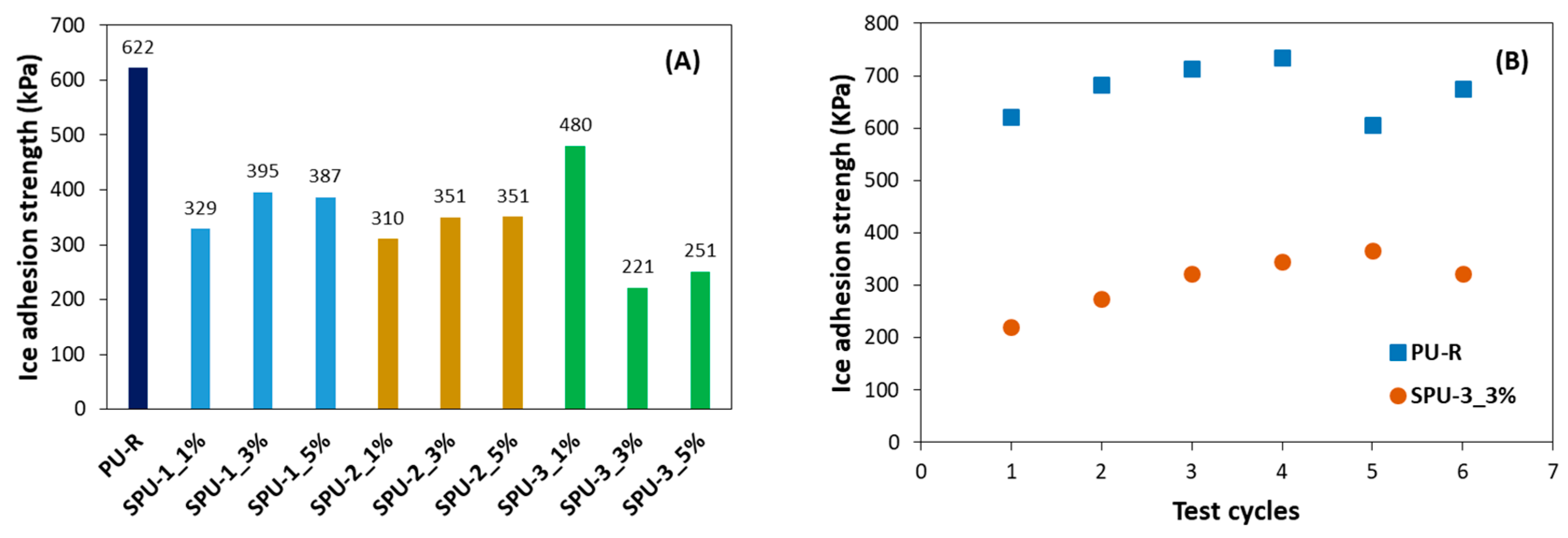
| PU-R | - | 0 | 69.0 | 77.4 | 20.4 |
| SPU-1_1% | SMP-1 | 1.0% | 103.7 | 108.0 | 80.2 |
| SPU-1_3% | 3.0% | 109.7 | 115.5 | 82.1 | |
| SPU-1_5% | 5.0% | 109.6 | 114.0 | 82.0 | |
| SPU-2_1% | SMP-2 | 1.0% | 100.0 | 101.2 | 78.3 |
| SPU-2_3% | 3.0% | 109.0 | 114.0 | 80.5 | |
| SPU-2_5% | 5.0% | 109.3 | 115.9 | 79.4 | |
| SPU-3_1% | SMP-3 | 1.0% | 96.9 | 100.7 | 69.4 |
| SPU-3_3% | 3.0% | 109.5 | 114.8 | 78.8 | |
| SPU-3_5% | 5.0% | 112.0 | 117.5 | 81.5 |
| Coatings | Elemental Content (at.%) | ||||
|---|---|---|---|---|---|
| C 1s | N 1s | O 1s | F 1s | Si 2p | |
| PU-R | 69.38 | 2.79 | 20.79 | 0 | 7.04 |
| SPU-1_1% | 59.11 | 4.31 | 13.14 | 20.08 | 3.37 |
| SPU-1_3% | 56.66 | 4.96 | 9.56 | 27.96 | 0.87 |
| SPU-1_5% | 56.16 | 4.87 | 9.18 | 28.95 | 0.85 |
| SPU-2_1% | 58.56 | 4.00 | 14.28 | 18.21 | 4.95 |
| SPU-2_3% | 56.83 | 4.73 | 9.41 | 27.95 | 1.08 |
| SPU-2_5% | 56.31 | 4.49 | 11.02 | 25.16 | 3.03 |
| SPU-3_1% | 58.76 | 3.39 | 16.91 | 13.05 | 7.89 |
| SPU-3_3% | 56.05 | 3.64 | 14.05 | 19.07 | 7.19 |
| SPU-3_5% | 56.00 | 4.24 | 11.92 | 23.36 | 4.48 |
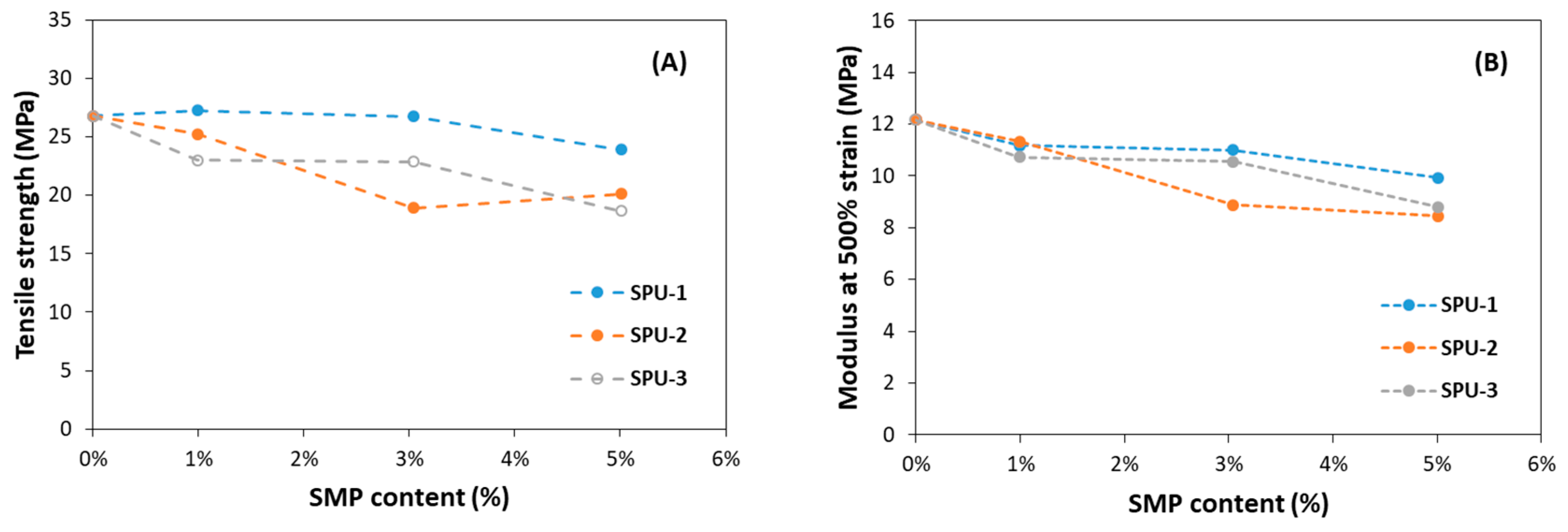
| Tensile Strength (MPa) | Stress at 300% Strain (MPa) | Stress at 500% Strain (MPa) | Elongation at Break (%) | Tensile Set (%) | |
|---|---|---|---|---|---|
| PU-R | 26.8 | 5.4 | 12.2 | 640% | 25% |
| SPU-1_1% | 27.2 | 5.2 | 11.2 | 680% | 20% |
| SPU-1_3% | 26.7 | 5.2 | 11.0 | 700% | 20% |
| SPU-1_5% | 23.9 | 4.9 | 9.9 | 720% | 30% |
| SPU-2_1% | 25.2 | 5.2 | 11.3 | 690% | 20% |
| SPU-2_3% | 18.9 | 4.5 | 8.9 | 690% | 20% |
| SPU-2_5% | 20.1 | 4.2 | 8.5 | 730% | 30% |
| SPU-3_1% | 23.0 | 5.1 | 10.7 | 690% | 25% |
| SPU-3_3% | 22.9 | 5.0 | 10.6 | 700% | 35% |
| SPU-3_5% | 18.7 | 4.5 | 8.8 | 700% | 30% |
Publisher’s Note: MDPI stays neutral with regard to jurisdictional claims in published maps and institutional affiliations. |
© 2022 by the authors. Licensee MDPI, Basel, Switzerland. This article is an open access article distributed under the terms and conditions of the Creative Commons Attribution (CC BY) license (https://creativecommons.org/licenses/by/4.0/).
Share and Cite
Song, N.; Benmeddour, A. Erosion Resistant Hydrophobic Coatings for Passive Ice Protection of Aircraft. Appl. Sci. 2022, 12, 9589. https://doi.org/10.3390/app12199589
Song N, Benmeddour A. Erosion Resistant Hydrophobic Coatings for Passive Ice Protection of Aircraft. Applied Sciences. 2022; 12(19):9589. https://doi.org/10.3390/app12199589
Chicago/Turabian StyleSong, Naiheng, and Ali Benmeddour. 2022. "Erosion Resistant Hydrophobic Coatings for Passive Ice Protection of Aircraft" Applied Sciences 12, no. 19: 9589. https://doi.org/10.3390/app12199589
APA StyleSong, N., & Benmeddour, A. (2022). Erosion Resistant Hydrophobic Coatings for Passive Ice Protection of Aircraft. Applied Sciences, 12(19), 9589. https://doi.org/10.3390/app12199589