Abstract
The tunnels in present-day cities are experiencing varying degrees of loading conditions ranging from static to extreme loading. Therefore, the stability of underground tunnels needs to be analyzed and understood for safer and strengthened design. The present study was conducted to simulate the impact loading conditions due to a missile traveling at a velocity of 5 Mach for different rock tunnels. The nonlinear continuum finite element analysis has been carried out through Abaqus and Explicit. The four different types of sandstones considered in the present study include Kota, Jamrani, Singrauli, and Jhingurda sandstones. An elastoplastic Mohr–Coulomb constitutive material model has been considered to model the behavior of rock surrounding the tunnel opening. The tunnel has an opening of 7 m in diameter (d), and 50 m in height and breadth, with 50 m of longitudinal length. The deformation and stress in the rock and the damage to the concrete lining have been compared in different cases. The Concrete–Damage–Plasticity (CDP) model and the Johnson–Cook model were considered for modelling of the RC lining and steel reinforcement. It was concluded that Jhingurda sandstone has maximum deformations due to impacts caused by missiles.
1. Introduction
Due to the rapid migration of the population from rural to urban cities, the demand for better, faster, and safer modes of transportation arises. In addition, the horizontal expansion of residential construction has created a need for subsurface construction. Therefore, the need for the design and research of tunnels and other underground structures has arisen. A number of studies have been carried out by researchers to understand the different aspects of tunnel stability [1,2,3,4,5,6,7,8,9,10,11,12].
Subsurface structures, especially tunnels and caverns, have been an integral part of the defense strategy of the country. The stability and equilibrium of these structures need to be studied for extreme loading events such as seismic loading, blast, and impact loading. Therefore, a number of researchers have studied the behavior of tunnels under varying types of loading conditions [13,14,15,16,17]. However, there are few studies that depict the performance of underground tunnels constructed in rock when subjected to impact load.
The numerical tools for computation and modelling have been used by researchers to study the stability of tunnels under varying impact loading conditions. Gao et al. [18] studied the behavior of intact rocks under an impact load using a commercial tool, LS-DYNA. They proposed a relationship and a model to study the behavior of intact rocks under impact loads. The model was validated with high accuracy using experimental results. Experimental and numerical simulations have been carried out by Aziznejad et al. [19] using a distinct element code to study the response of rock mass under an impact load. The propagation of cracks in the rock tunnel was studied by Zhou et al. [20] under the impact loading condition, and it was found that the speed of crack propagation is non-uniform; therefore, cracks may stop propagating suddenly. Zhou et al. [21] considered the change in orientation of the impact with respect to the tunnel model. They categorized different types of failure modes in tunnels under impact loading conditions. Zhou et al. [22] had concluded that the tunnel experiences different types of failure modes due to impact load and found that radial cracks propagate in the tunnel from the edge of the tunnel.
Therefore, it may be summarized that the strength of tunnels in rocks under impact loads has been rarely studied in the open literature. However, there is still a significant scope and a need for further study. Sedimentary rocks cover the majority of metropolitan areas in different countries of the world. However, the impact resistance of these rocks against soft and hard missiles has received little attention from previous researchers. Moreover, sandstone is found in significant areas near the borders of strong military countries like India, Pakistan, and China. Hence, it needs to be studied for impact loading conditions. Consequently, the present paper has considered four different types of sandstone: Jhingurda, Singrauli, Jamrani, and Kota. A missile having 100 kg of weight and a velocity of 5 Mach has been considered to simulate the impact loading conditions for different rock tunnels. The nonlinear elastoplastic continuum FE (finite element) method has been adopted to understand the adverse effects of impact loading on rock tunnels.
2. Impact Loading Simulation
The impact resistance of four different sandstone rock tunnels has been studied in the present paper. A missile has been modelled based on the description given by Vidanović et al. [23]. The missile has a 0.7637 m length and a mass of 100 kg, modelled as a discrete part. The commercial software Abaqus has been used, and explicit mode has been selected for the simulation. The missile had a 5 Mach velocity before it hit the ground surface above the rock through which a tunnel has been constructed. The geometry of the tunnel has been considered based on the DMRC design specifications and published articles [24,25,26]. A dynamic explicit analysis has been carried out in the finite element tool Abaqus. In Abaqus, a step is time allotted for a particular analysis. However, according to the demand of output frame, it breaks the overall time allotted in small increments. In the present analysis, the step time is 0.035.
2.1. Geometry
The rock surrounding the tunnels has been modelled as a bigger size element having a three-dimensional size of 50 m × 50 m × 50 m and 12.5 m of overburden depth. The tunnel has an opening of 7 m in diameter and has been supported by a reinforced concrete liner of 0.35 m in thickness. The liner has an M30 grade of concrete. The concrete liner has reinforcement of steel bars of Weldox 460E grade in the longitudinal and circular directions. The details of the reinforcement and tunnel geometry are presented in Figure 1.
Figure 1.
Geometry of finite element model for impact loading simulation. (a) Abaqus model of Missile, 0.7637 m in length and a mass of 100 kg with 5 Mach velocity (b) Tunnel with an opening of 7 m in diameter and supported by a reinforced concrete(M30) liner of 0.35 m in thickness. (c) The rock surrounding the tunnels of 50 m × 50 m × 50 m and 12.5 m of overburden depth.
2.2. Input Properties of Materials
The rock mass surrounding the tunnel has been considered as a nonlinear elastoplastic material. The Mohr–Coulomb failure model has been used to incorporate the nonlinearity of four different types of sandstones. The four sandstone rocks considered in the present paper are Jhingurda, Singrauli, Jamrani, and Kota. The input parameters are taken from Rao et al. [27]. Table 1 represents the different physical and mechanical properties of rocks used in the present simulation.

Table 1.
Four different sandstone rock surrounding the tunnel opening.
Similarly, the nonlinear behavior has been considered for steel bars by providing the elastoplastic properties of steel. Table 2 and Figure 2 show the properties of steel reinforcement used in this study. The interaction between the steel bars and concrete of the liner is achieved by embedding the circular and longitudinal reinforcement. The embedment constraint in the interaction module applied the proper bond between the steel and concrete, creating a reinforced concrete liner for the rock tunnel. The Johnson–Cook model [28] has been used for modelling the steel bars and properties are taken from Borvik et al. [29]. Borvik et al. [29] had performed a series of experiments on the steel under different strain rate and at varying temperature range.
Table 2.
Elastoplastic properties of reinforced steel with Weldox 460 E grade.
Figure 2.
Plastic behavior of steel reinforcement material.
Moreover, the concrete liner has been considered as M30 grade and its nonlinear elastoplastic behavior has been simulated through the Concrete Damage Plasticity model. It also incorporated the damage characteristic of the concrete and, therefore, proved to be useful in studying the overall failure of the internal lining.
The M30 grade of concrete has a mass density of 2500 kg/m3 and a Young’s modulus of 26.6 GPa, with a 0.20 Poisson’s ratio. Moreover, the dilation angle and eccentricity of 31 degrees and 0.1, respectively, have been considered. The variation in stress and damage corresponding to strain for the M30 grade of concrete are shown in Figure 3 and Figure 4, respectively.
Figure 3.
Input of stress–strain variation for M30 grade of concrete liner used in tunnel.
Figure 4.
Damage parameter variation with strain for M30 grade of concrete.
2.3. Meshing, Loading, Boundary and Interaction Conditions
The rock mass surrounding the tunnel has been meshed as C3D8R (Continuum Three-dimensional eight-nodded reduced integration solid Brick element), as suggested and used by Zaid and Sadique [30,31], Zaid and Shah [32] and Zaid et al. [33,34,35,36,37]. The element size of 0.7 has been used based on mesh convergence, and this type of mesh is defined as brick-type element, which has eight nodes. The steel bars are modelled as beam-type element, i.e., B31, as suggested and used by Zaid and Sadique [38,39,40]. The steel bars elements have an element size of 0.05. The missile has been meshed by the R3D4 element type to make it rigid and discrete. The general hard contact and frictionless tangential contact has been assigned to the whole model. The embedment interaction has been used to model the reinforced concrete liner by embedding the steel bars in concrete liner. The base of the rock has a fixed support as the rock mass extends to infinite depth, and the sides of the model have roller supports, which allow vertical movement but restrain other directional movement of rock mass. One set of simulation takes around six and a half CPU hours on a 64GB RAM system with a Dell Precision Tower 7810. General hard contact and frictionless tangential contact have been assigned to the whole model. The embedment interaction has been used to model the reinforced concrete liner by embedding the steel bars in the concrete liner.
3. Validation of Dynamic Loading
In order to validate the present finite element simulation, an experimental study has been simulated using the present methodology and numerical results are compared with the experimental study by Andersson [41], as shown in Table 3. A steel mass weighing 600 kg was considered for impact loading on 0.2 m × 0.2 m area in the middle of a slab. The height of fall was varied from 1 m to 2 m on the concrete slab having a 1.75 m × 1.75 m cross section and a 0.12 m thickness. The size of the slab, loading conditions, and the properties of the model have been adopted as per the report by Andersson [41].
Table 3.
Comparison of results of properties of reinforced steel.
4. Results and Discussion
Commercial software based on the finite element method, i.e., Abaqus/Explicit, has been used for modelling and analysis. Four different sandstone rocks, Jhingurda, Singrauli, Jamrani, and Kota, were considered. A generally used design specification for metro tunnels has been used based on Delhi Metro Rail Corporation designs. A missile having a 5 Mach velocity and weighing 100 kg has been considered. The simulation has been run for 30 milliseconds, which is the time required by a missile to hit the rock ground from 100 m away.
Figure 5 has been plotted to compare the deformation variation with time when a missile hits the ground surface for all the sandstone rocks considered in the present study. It has been observed that the amplitude of deformation for Jhingurda sandstone is the maximum, having a magnitude of 2.45 m. Maximum deformations of 1.35 m, 1.03 m, and 0.76 m have been observed for Singrauli, Jamrani, and Kota rocks prospectively at the ground surface. Therefore, Kota sandstone has shown maximum resistance to missile penetration, while Jhingurda sandstone has the least resistance to missile penetration.
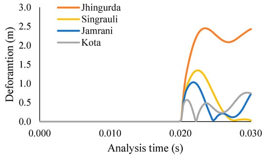
Figure 5.
Variation in deformation with time to compare the ground surface behavior under impact loading of 100 kg missile.
The deformation profile is one of the important output results for understanding the internal behavior of a tunnel. Figure 6 shows the comparison of the deformation profiles of four sandstone rocks. The deformation profile for Jhingurda sandstone follows a smooth curvature, while the curvature becomes distorted and non-uniform for other types of sandstone. It has also been observed that as the strength of sandstone increases, the peak deformation gets decreased, while the length of tunnel under disturbance increases with the increase in the strength of sandstone. Moreover, a slight bulging has been observed in all the sandstones except for Jhingurda sandstone. Therefore, it may be concluded that weaker sandstone requires strengthening for a smaller area after an impact loading event, while high-strength sandstone will require repair for a longer portion of the tunnel.

Figure 6.
Comparison of deformation profile generated under the response of impact load.
Particle velocity is one of the significant output results in the dynamic loading analysis of rock tunnels. Therefore, the peak velocity at the ground surface of different sandstone rocks is shown in Figure 7 for comparison. The peak of the particle velocity graph has been observed at 20.41 milliseconds in each case of sandstone rock. However, the variation of particle velocity follows a separate path for different rocks, but the pattern of the particle velocity plot remains similar in all the cases. Figure 8 represents the peak acceleration at the ground surface when a missile hits the different sandstone rocks. In the case of Jhingurda sandstone, the magnitude of peak velocity and acceleration is greatest. Moreover, the pattern of variation in acceleration and velocity remains similar, and therefore, it is independent of the type of sandstone.
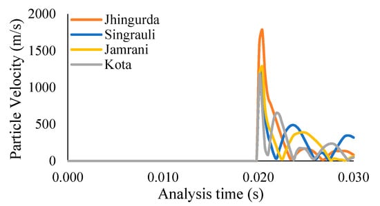
Figure 7.
Comparison of particle velocity at ground surface under present impact loading condition.
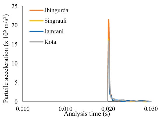
Figure 8.
Comparison of particle acceleration at ground surface under present impact loading condition.
Figure 9 shows the deformation contours of Jhingurda, Singrauli, Jamrani, and Kota sandstone when a 100 kg missile moving at the velocity of 5 Mach hits the ground surface of the rock-containing tunnel. It has been observed that the brittleness and strength of rock have a significant influence on the deformation zone. In the cases of Jhingurda, Singrauli, Jamrani, and Kota, the maximum deformation at the crown is 4.94 mm, 2.75 mm, 2.61 mm, and 1.04 mm, respectively. It can be concluded that Kota sandstone has minimum deformation, and therefore, it is the safest sandstone rock under impact loading conditions. However, the area of disturbance is maximum in the case of Kota sandstone, and vibrations may reach the tunnel crown in a shorter time as compared to other sandstones.
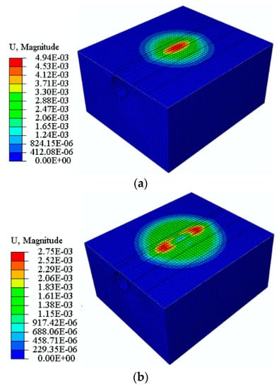
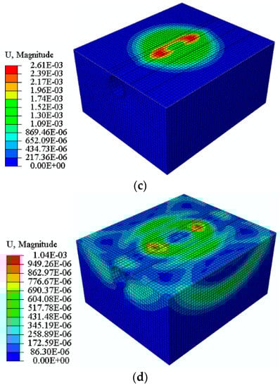
Figure 9.
Deformation contours of (a) Jhingurda, (b) Singrauli, (c) Jamrani and (d) Kota when an impact loading occurs due to 100 kg missile.
Figure 10 has been plotted to compare the serviceability of reinforced concrete liners under impact loading conditions in the case of different types of sandstone. Tension damage has been observed in each type of sandstone. However, the area of the damaged zone increases with the strength and brittleness of sandstone. Therefore, reinforced concrete liner has maximum tensile damage in Kota sandstone (0.99) and less tension damage in the case of Jhingurda sandstone (0.017). It has been concluded that the consequences of an impacting projectile reach the tunnel lining when constructed in strong and brittle sandstone, or vice-versa. In addition, the tensile damage in all the different types of sandstones considered in the present study remains concentrated at the outer periphery of the liner.
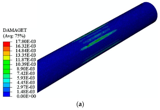
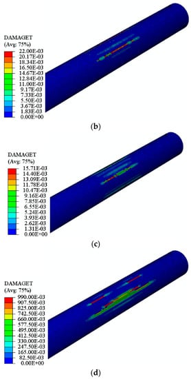
Figure 10.
Tension damage contours of (a) Jhingurda, (b) Singrauli, (c) Jamrani, and (d) Kota sandstone tunnel when an impact loading occurs due to a 100 kg missile.
The in-depth view of lining performance has been studied by comparing the deformation at the reinforcement cage of steel bars in the case of different rocks, as shown in Figure 11. The maximum value of deformation has been noted for Jhingurda sandstone, while the maximum value of deformation remains concentrated at the crown of the tunnel.
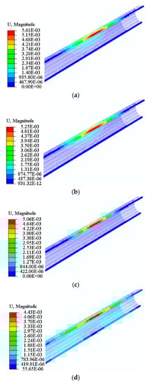
Figure 11.
Deformation contours of steel bar reinforcement cage for (a) Jhingurda, (b) Singrauli, (c) Jamrani, and (d) Kota sandstone tunnel when an impact loading occurs due to a 100 kg missile.
5. Conclusions
The present study of finite element simulation for rock tunnel resistance against impact loading has four different sandstone rocks surrounding a 5 m diameter reinforced concrete tunnel lining. The major conclusions drawn from the present study are as follows:
- The Kota sandstone has 2.22-times, 0.77-times, 0.35-times more impact resistance than Jhingurda, Singrauli and Jamrani sandstone, respectively. Therefore, the impact resistance of a rock tunnel is a function of cohesion and friction angle.
- The deformation profile for Jhingurda sandstone follows a smooth curvature while the curvature becomes distorted and non-uniform for other types of sandstone. It has also been observed that as the strength of sandstone increases, the peak deformation decreases, while the length of tunnel under disturbance increases with the increase in the strength of sandstone. In addition, it has been concluded that weaker sandstone requires strengthening for a smaller area after an impact loading event while high-strength sandstone will require repair for a longer portion of the tunnel.
- The magnitude of peak velocity and acceleration is maximum in case of Jhingurda sandstone at 20.41 milliseconds. Moreover, the pattern of variation in acceleration and velocity remains similar, and therefore, it is independent of the type of sandstone.
- It can be concluded that Kota sandstone has minimum deformation and is therefore the safest sandstone rock under impact loading conditions. However, the area of disturbance is greatest in the case of Kota sandstone, and vibrations may reach the tunnel crown in a shorter time in comparison to other rocks.
- The effect of impact loading has reached the tunnel lining when constructed in strong and brittle sandstone, or vice versa. In addition, the tensile damage in all the different types of sandstones considered in the present study remains concentrated at the outer periphery of the liner. The steel reinforcement cage experiences maximum deformation at the crown position in all the cases, while the maximum magnitude of deformation occurred in the case of Jhingurda sandstone.
Author Contributions
M.R.S.: drafting—data collection and preparation of the manuscript, writing review and editing, S.A.: drafting—preparation of the manuscript, revision and correction; A.H.A.: composing—reviewing, fund acquisition and modifying; A.S.A.: composing—reviewing, and modifying; W.S.: reviewing and modifying. All authors have read and agreed to the published version of the manuscript.
Funding
The authors acknowledge the support provided by Researchers Supporting. Project Number (RSP2022R473), King Saud University, Riyadh, Saudi Arabia.
Institutional Review Board Statement
Not applicable.
Informed Consent Statement
Not applicable.
Data Availability Statement
Not applicable.
Acknowledgments
Authors acknowledge the support provided by King Saud University, Saudi Arabia, and Aligarh Muslim University, India, to carry out this study.
Conflicts of Interest
The authors declare no conflict of interest.
References
- Do, N.A.; Oreste, P.; Dias, D.; Antonello, C.; Djeran-Maigre, I.; Livio, L. Stress and strain state in the segmental linings during mechanized tunnelling. Geomech. Eng. 2014, 7, 75–85. [Google Scholar] [CrossRef]
- Do, N.A.; Dias, D.; Oreste, P.; Djeran-Maigre, I. 2D numerical investigations of twin tunnel interaction. Geomech. Eng. 2014, 6, 263–275. [Google Scholar] [CrossRef]
- Eskandari, F.; Goharrizi, K.G.; Hooti, A. The impact of EPB pressure on surface settlement and face displacement in intersection of triple tunnels at Mashhad metro. Geomech. Eng. 2018, 15, 769–774. [Google Scholar] [CrossRef]
- Ghasemi, S.H.; Nowak, A.S. Reliability analysis of circular tunnel with consideration of the strength limit state. Geomech. Eng. 2018, 15, 879–888. [Google Scholar] [CrossRef]
- Mazek, S.A. Evaluation of surface displacement equation due to tunnelling in cohesionless soil. Geomech. Eng. 2014, 7, 55–73. [Google Scholar] [CrossRef]
- Miranda, T.; Dias, D.; Pinheiro, M.; Eclaircy-Caudron, S. Methodology for real-time adaptation of tunnels support using the observational method. Geomech. Eng. 2015, 8, 153–171. [Google Scholar] [CrossRef]
- Fahimifar, A.; Ghadami, H.; Ahmadvand, M. The ground response curve of underwater tunnels, excavated in a strain-softening rock mass. Geomech. Eng. 2015, 8, 323–359. [Google Scholar] [CrossRef]
- Nawel, B.; Salah, M. Numerical modeling of two parallel tunnels interaction using three-dimensional finite elements method. Geomech. Eng. 2015, 9, 775–791. [Google Scholar] [CrossRef]
- Nikadat, N.; Marji, M.F. Analysis of stress distribution around tunnels by hybridized fsm and ddm considering the influences of joints parameters. Geomech. Eng. 2016, 11, 269–288. [Google Scholar] [CrossRef]
- Khezri, N.; Mohamad, H.; Fatahi, B. Stability assessment of tunnel face in a layered soil using upper bound theorem of limit analysis. Geomech. Eng. 2016, 11, 471–492. [Google Scholar] [CrossRef]
- Aalianvari, A.; Soltani-Mohammadi, S.; Rahemi, Z. Estimation of geomechanical parameters of tunnel route using geostatistical methods. Geomech. Eng. 2018, 14, 453–458. [Google Scholar] [CrossRef]
- Zidan, A.F.; Ramadan, O.M. A hybrid MC-HS model for 3D analysis of tunnelling under piled structures. Geomech. Eng. 2018, 14, 479–489. [Google Scholar] [CrossRef]
- Khan, M.A.; Sadique, M.R.; Harahap, I.H.; Zaid, M.; Alam, M.M. Static and Dynamic Analysis of the Shielded Tunnel in Alluvium Soil with 2D FEM Model. Transp. Infrastruct. Geotechnol. 2022, 9, 73–100. [Google Scholar] [CrossRef]
- Sadique, R.M.; Zaid, M.; Naqvi, M.W.; Akhtar, M.F. Analysis of Underground Renewable Energy Storage Tunnels Subjected to Capricious Superstructures. In Renewable Power for Sustainable Growth, Proceedings of the International Conference on Renewal Power (ICRP 2020), Rajouri, India, 17–18 April 2020; Lecture Notes in Electrical Engineering; Springer: Singapore, 2021; Volume 723. [Google Scholar]
- Sadique, M.R.; Ali, A.; Zaid, M.; Masroor Alam, M. Experimental and Numerical Modeling of Tunneling-Induced Ground Settlement in Clayey Soil. In Advances in Geotechnics and Structural Engineering, Proceedings of the TRACE 2020, Noida, India, 20–21 August 2020; Lecture Notes in Civil Engineering; Springer: Singapore, 2021; Volume 143. [Google Scholar]
- Sadique, M.R.; Zaid, M.; Alam, M.M. Rock Tunnel Performance Under Blast Loading Through Finite Element Analysis. Geotech. Geol. Eng. 2022, 40, 35–56. [Google Scholar] [CrossRef]
- Zaid, M.; Mishra, S. Numerical Analysis of Shallow Tunnels Under Static Loading: A Finite Element Approach. Geotech. Geol. Eng. 2021, 39, 2581–2607. [Google Scholar] [CrossRef]
- Gao, F.; Hou, A.; Yang, X. Numerical Analysis of Dynamic Mechanical Properties for Rock Sample under Strong Impact Loading. Int. J. Inf. Eng. Electron. Bus. 2010, 2, 10–16. [Google Scholar] [CrossRef]
- Aziznejad, S.; Esmaieli, K.; Hadjigeorgiou, J.; Labrie, D. Responses of jointed rock masses subjected to impact loading. J. Rock Mech. Geotech. Eng. 2018, 10, 624–634. [Google Scholar] [CrossRef]
- Zhou, L.; Zhu, Z.; Wang, M.; Ying, P.; Dong, Y. Dynamic propagation behavior of cracks emanating from tunnel edges under impact loads. Soil Dyn. Earthq. Eng. 2018, 105, 119–126. [Google Scholar] [CrossRef]
- Zhou, L.; Zhu, Z.; Dong, Y.; Fan, Y.; Zhou, Q.; Deng, S. The influence of impacting orientations on the failure modes of cracked tunnel. Int. J. Impact Eng. 2019, 125, 134–142. [Google Scholar] [CrossRef]
- Zhou, L.; Zhu, Z.; Dong, Y.; Ying, P.; Wang, M. Study of the fracture behavior of mode I and mixed mode I/II cracks in tunnel under impact loads. Tunn. Undergr. Space Technol. 2019, 84, 11–21. [Google Scholar] [CrossRef]
- Vidanović, N.; Rašuo, B.; Kastratović, G.; Maksimović, S.; Ćurčić, D.; Samardžić, M. Aerodynamic–structural missile fin optimization. Aerosp. Sci. Technol. 2017, 65, 26–45. [Google Scholar] [CrossRef]
- DMRC. Design Specifications of DMRC; DMRC: New Delhi, India, 2015. [Google Scholar]
- Zaid, M. Dynamic stability analysis of rock tunnels subjected to impact loading with varying UCS. Geomech. Eng. 2021, 24, 505–518. [Google Scholar] [CrossRef]
- Zaid, M. Three-dimensional finite element analysis of urban rock tunnel under static loading condition: Effect of the rock weathering. Geomech. Eng. 2021, 25, 99–109. [Google Scholar] [CrossRef]
- Rao, K.; Rao, G.; Ramamurthy, T. Strength Behaviour of Some Indian Sandstones. In Proceedings of the Asian Regional Conference on Geotechnical Problems and Practices in Foundation Engineering, Colombo, Sri Lanka, 25–27 February 1986; pp. 1–6. [Google Scholar]
- Johnson, G.R.; Cook, W.H. A Constitutive modeling and data for metals subjected to large strain rates and high temperatures. In Proceedings of the 7th International Symposium on Ballistics, The Hague, The Netherlands, 19–21 April 1983. [Google Scholar]
- Borvik, T.; Hopperstad, O.S.; Berstad, T.; Langseth, M. A computational model of viscoplasticity and ductile damage for impact and penetration. Eur. J. Mech. A Solids 2001, 20, 685–712. [Google Scholar] [CrossRef]
- Zaid, M.; Rehan Sadique, M. Dynamic analysis of tunnels in western ghats of indian peninsula: Effect of shape and weathering. In Recent Trends in Civil Engineering; Springer: Singapore, 2021; Volume 77. [Google Scholar]
- Zaid, M.; Rehan Sadique, M. A Simple Approximate Simulation Using Coupled Eulerian–Lagrangian (CEL) Simulation in Investigating Effects of Internal Blast in Rock Tunnel. Indian Geotech. J. 2021, 51, 1038–1055. [Google Scholar] [CrossRef]
- Zaid, M.; Shah, I.A. Blast-Resistant Stability Analysis of Triple Tunnel. In Advances in Geotechnics and Structural Engineering, Proceedings of the TRACE 2020, Noida, India, 20–21 August 2020; Lecture Notes in Civil Engineering; Springer: Singapore, 2021; Volume 143. [Google Scholar]
- Zaid, M.; Athar, M.F.; Sadique, M.R. Effect of Rock Weathering on the Seismic Stability of Different Shapes of the Tunnel. In Lecture Notes in Civil Engineering, Proceedings of the Indian Geotechnical Conference, 2019, Surat, India, 19–21 December 2021; Springer: Singapore, 2021; Volume 137. [Google Scholar]
- Zaid, M.; Faraz Athar, M.; Rehan Sadique, M. Interaction of Transmission Tower Footing with Twin Rock Tunnel. In Advances in Geotechnics and Structural Engineering, Proceedings of the TRACE 2020, Noida, India, 20–21 August 2020; Lecture Notes in Civil Engineering; Springer: Singapore, 2021; Volume 143. [Google Scholar]
- Zaid, M.; Naqvi, M.W.; Sadique, M.R. Stability of Arch Tunnel in Different Magnitude of Earthquake with Effect of Weathering in Western Ghats of India. In Lecture Notes in Civil Engineering, Proceedings of the Indian Geotechnical Conference 2019, Surat, India, 19–21 December 2021; Springer: Singapore, 2021; Volume 138. [Google Scholar]
- Zaid, M.; Sadique, M.R.; Alam, M.M. Blast Resistant Analysis of Rock Tunnel Using Abaqus: Effect of Weathering. Geotech. Geol. Eng. 2021, 40, 809–832. [Google Scholar] [CrossRef]
- Zaid, M.; Sadique, M.R.; Alam, M.M. Blast analysis of tunnels in Manhattan-Schist and Quartz-Schist using coupled-Eulerian–Lagrangian method. Innov. Infrastruct. Solut. 2021, 6, 69. [Google Scholar] [CrossRef]
- Zaid, M.; Sadique, M.R. Effect of joint orientation and weathering on static stability of rock slope having transmission tower. In Proceedings of the 7th Indian Young Geotechnical Engineers Conference 2019, Silchar, India, 15–16 March 2019; Volume 5, pp. 414–422. [Google Scholar]
- Zaid, M.; Sadique, M.R. Numerical modelling of internal blast loading on a rock tunnel. Adv. Comput. Des. 2020, 5, 417–443. [Google Scholar] [CrossRef]
- Zaid, M.; Sadique, M.R. The response of rock tunnel when subjected to blast loading: Finite element analysis. Eng. Rep. 2021, 3, e12293. [Google Scholar] [CrossRef]
- Andersson, A. Impact Loading on Concrete Slabs: Experimental Tests and Numerical Simulation; KTH: Stockholm, Sweden, 2014. [Google Scholar]


Publisher’s Note: MDPI stays neutral with regard to jurisdictional claims in published maps and institutional affiliations. |
© 2022 by the authors. Licensee MDPI, Basel, Switzerland. This article is an open access article distributed under the terms and conditions of the Creative Commons Attribution (CC BY) license (https://creativecommons.org/licenses/by/4.0/).