1. Introduction
Fifth-generation (5G) systems are considered to be potential substitutes to overcome the constraints of present communication technologies. The 5G technology is divided into two broad spectrums, namely sub-6 GHz and millimeter-wave (mmWave) [
1,
2,
3,
4]. The Federal Communications Commission (FCC) has suggested the mmWave spectrum (24 GHz, 28 GHz, 37–39 GHz, and 60 GHz) as the operational frequency for 5G connectivity. However, the propagation problems in the proposed spectrum could affect the deployment of the network. The 5G mmWave frequency bands are suitable for dense 5G small cell networks in urban areas with high capacity demands, as well as larger-area macro cells. The International Telecommunication Union (ITU) has therefore designated the 5G mid-band for broadband cellular communication systems. The sub-6 GHz range, also referred to as the 5G mid-band, has the ability to extend coverage while reducing propagation losses. In order to accommodate higher data traffic for connectivity with higher data rates, a spectrum of 100 MHz is needed, which can easily be managed with the use of sub-6 GHz frequency bands. Additionally, to achieve high data rates and high CC, a minimum of six radiating elements is required.
In the literature, several MIMO antenna systems have been proposed for the sub-6 GHz 5G spectrum. In [
5], a six-element MIMO antenna was presented, which resonates in the frequency range of 3.4–3.6 GHz. The single element area was noted to be 24 mm
2, while the isolation among radiating elements was noted to be 11 dB. In [
6], an open-ended slot radiation element-based MIMO antenna system was designed, which exhibits a 400 MHz impedance bandwidth ranging from 3.4 GHz to 3.8 GHz. They utilized 18 antenna elements for MIMO configuration and observed CC of 80 bps/Hz with 16 dB of isolation between antenna elements. In [
7], an eight-element uni-planar MIMO antenna was presented, covering LTE band 42 over 3.4–3.6 GHz. A pair of orthogonally placed antenna elements are placed on each corner of the smartphone board. This arrangement leads to the achievement of high isolation between antenna elements, but the signal integrity is compromised because the antenna elements are placed very close to other electronic components.
Along with LTE band 42 (3.4–3.6 GHz) and LTE band 43 (3.6–3.8 GHz), there are several other 5G bands, such as LTE band 46 (5.1–5.8 GHz), LTE band 41 (2.6–2.8 GHz), and n55 (4.4–4.8 GHz), which can be utilized to fulfill the basic requirements of 5G communication technology. In [
8], a wideband MIMO antenna system was designed and presented for LTE band 41 and LTE band 42. The designed MIMO antenna exhibits a 1 GHz impedance bandwidth in the frequency range of 2.6–3.6 GHz. The MIMO configuration consists of eight elements, of which four elements are printed on the main board, while the four radiating elements are mounted on the side-edge frame of the smartphone. This kind of configuration leads to a complex design topology and also offers difficulties in the fabrication process. In [
9], an eight-element MIMO antenna for the sub-6 GHz LTE band 42 was presented. The antenna elements were printed on the side-edge frame of the smartphone. To achieve high isolation, a decoupling structure was designed between the antenna elements. The designed MIMO antenna offers an impedance bandwidth of 300 MHz from 3.3 GHz to 3.6 GHz. Furthermore, the addition of the decoupling structure excited a new resonance in the frequency range of 2.4–2.7 GHz.
A dual-band eight-element planar MIMO antenna was presented in [
10] for sub-6 GHz applications. The dual-band resonance was achieved by using an L-shaped slot on the ground plane. Similarly, in [
11,
12], dual-band MIMO antenna systems were designed for LTE bands 41 and 42, respectively. In [
13], an eight-element MIMO antenna was presented with a chip capacitive decoupler. The resonance bandwidth of the antenna varied over 3.33–3.69 GHz, and the efficiency was found to be >50% at 3.5 GHz. In [
14], a dual-band antenna operating at 3.38–3.82 GHz and 4.75–5.13 GHz was presented. The MIMO system showed an isolation value of 14 dB with the insertion of a decoupling structure. In [
15], an eight-element MIMO antenna was designed, which comprised an inverted S-shaped resonating strip with an inverted L-shaped radiator mounted on the side-edged frame of the smartphone. The designed antenna exhibits dual-band response ranging over 3.3–3.8 and 4.9–5.7 GHz. The isolation between the MIMO elements was noted to be 11 dB throughout the resonance bandwidth.
The MIMO antennas discussed above offer acceptable performance, but they suffer due to their design configuration. Accommodating a huge number of antennas with other electronic components can be tricky and hard to accomplish. Therefore, in this paper, an eight-element MIMO antenna system is presented for dual-band sub-6 GHz applications. The antenna elements are designed on the side-edge frame of the smartphone to provide space for other components used in mobile phone assembly. From the presented results, it is observed that the designed MIMO antenna resonates at two distinct 5G allotted bands, i.e., 3.4–3.6 GHz and 5.1–5.8 GHz. The isolation between the antenna elements is noted to be >18 dB for the 3.5 GHz frequency band and >12 dB for the 5.4 GHz frequency band. Furthermore, good diversity performance is observed for the proposed MIMO antenna, which makes it suitable for future 5G-enabled smartphone applications.
2. MIMO Antenna Design
Figure 1a shows the configuration of the proposed MIMO antenna system. One can observe from the figure that eight antenna elements are arranged on both side-edges of the smartphone printed circuit board (PCB). This kind of configuration provides more space for other RF components to be integrated on the smartphone PCB. The dimensions of the main PCB are noted to be 150 × 75 mm
2, while the dimensions of the side-edge are 150 × 8 mm
2. The distance among radiating elements is kept at 32.375 mm, as shown in
Figure 1b. The single element of the MIMO system consists of a P-shaped radiating element embedded inside a semi-rectangular resonating structure, as shown in
Figure 1c. The total size of the radiating element is noted to be 8 × 4.5 mm
2. The rest of the design parameters of the radiating element are also provided in
Figure 1c. In addition, a low-cost FR-4 substrate is used with a relative permittivity of 4.4 and a thickness of 0.8 mm.
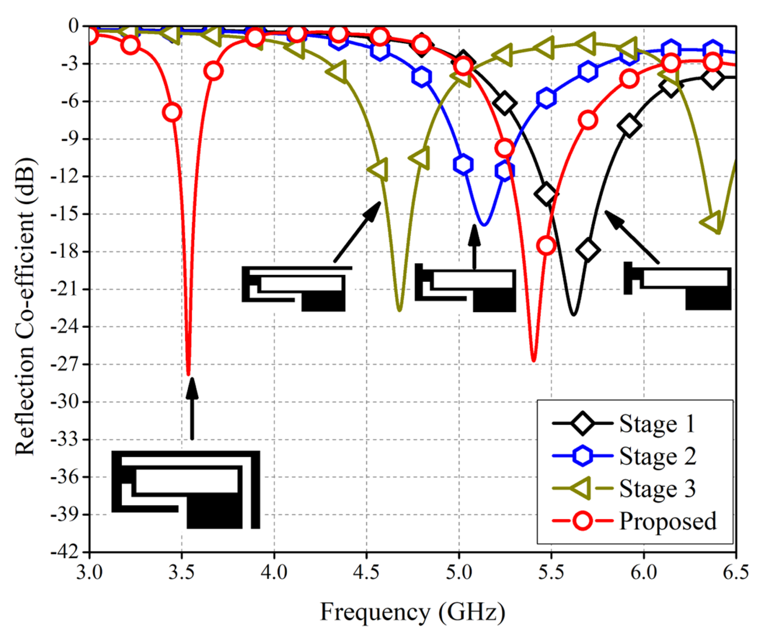
Figure 2 shows the evolution process of the proposed single antenna element. The proposed antenna design was implemented in four stages. In the first stage, a P-shaped radiating element is implemented with a small extended strip (see
Figure 2). This resonator provides resonance at a frequency of 5.6 GHz with an impedance bandwidth of 800 MHz, as shown in
Figure 2. In the second stage, an extension is made in the strip by adding a horizontal strip, which leads to an L-shaped resonator, as shown in
Figure 2. At this stage, a resonance frequency of 5.2 GHz was achieved with an impedance bandwidth of 400 MHz (see
Figure 2). In the third step, the length of the L-shaped horizontal strip was extended. With the extension of the horizontal strip, a dual-band resonance was achieved at 4.6 GHz and 6.4 GHz, as shown in
Figure 2. In the last step, a vertical strip was added to the inverted L-shaped resonator, which increased the current patch and shifted the resonances towards the desired frequency bands (3.5 GHz and 5.4 GHz), as shown in
Figure 2. The impedance bandwidths for both of the frequency bands were noted to be 200 MHz and 700 MHz, respectively.
The performance of the proposed single antenna element can further be verified with the help of surface current distribution (see
Figure 3). From the figure, it can be seen that for the first resonance (3.5 GHz), the current is induced strongly at the top right strip of the antenna (see
Figure 3a), while at 5.4 GHz, the strong current is distributed on the lower middle side of the radiating element, as shown in
Figure 3b.
3. Parametric Study
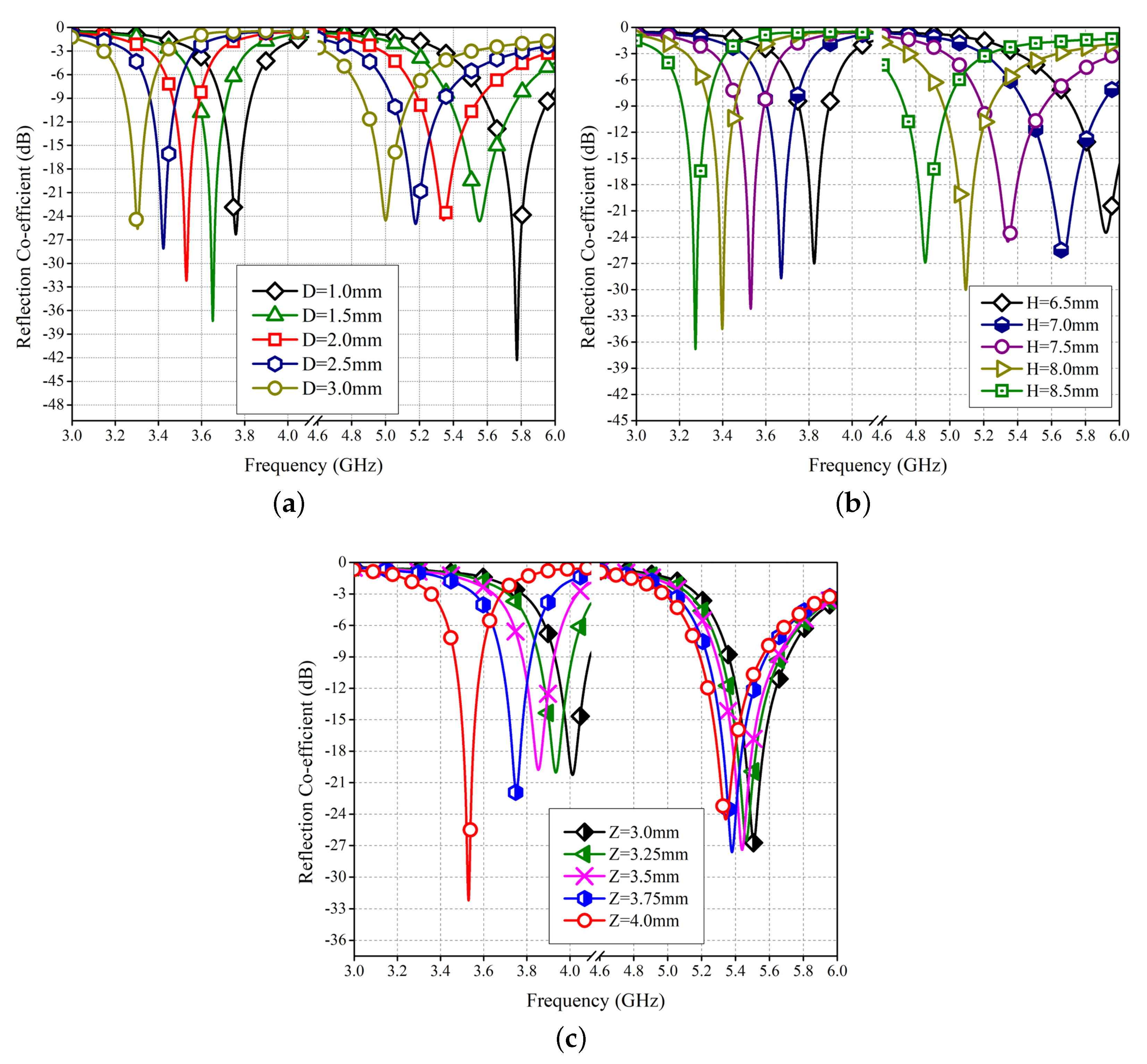
The performance of the proposed design is analyzed through a number of parametric studies. The parametric study is performed for three design parameters, such as “D”, “H”, and “Z”. First, the effect of parameter “D” on the antenna’s performance is analyzed. The value of “D” is changed from 1 to 3 mm, with a 0.5 mm interval. As seen from the figure, the parameter “D” has a significant effect on both resonances. As the length of the strip is increased, the resonant frequencies shift towards the lower bands, as shown in
Figure 4a. The optimum response is achieved for “D” = 2 mm, where the antenna resonates at 3.5 GHz and 5.4 GHz (see
Figure 4a). The same kind of effect is observed for parameter “H" when its value is changed from 6.5 to 8.5 mm, as shown in
Figure 4b. The optimum response is achieved at “H” = 7.5 mm. In the last, the value of “Z” is changed from 3 to 4 mm, and its effect on the antenna’s performance is observed and depicted in
Figure 4c. The parameter “Z” has more impact on the first resonance compared to the second resonance (see
Figure 4c). The second resonance slightly shifts towards the lower frequencies.
4. Simulation Results
The simulated S-parameters response of the proposed MIMO antenna system is shown in
Figure 5. The simulation of the proposed MIMO antenna was performed in CST Microwave Studio. Due to the symmetry, only one side of the MIMO system is considered.
Figure 5a shows the reflection coefficient response of Ant 1 to Ant 4. From the figure, it can be seen that all the antennas are resonating well at the desired bands of interest, as shown in
Figure 5a. The isolation between the antenna elements is shown in
Figure 5b. The isolation is noted to be >18 dB for the 3.5 GHz frequency band, and >12 dB for the 5.4 GHz frequency band.
Figure 6a,b shows the radiation and total efficiency of the MIMO antenna system. The radiation efficiency of Ant 1 and Ant 4 fluctuates between 62% and 71% (see
Figure 6a), while for Ant 2 and Ant 3, the radiation efficiency varies from 58% to 74%, as shown in
Figure 6b. The total efficiency for Ant 1 and Ant 4 ranges over 51–60% for both frequency bands, as shown in
Figure 6a. For Ant 2 and Ant 3, the total efficiency varies in the range of 48–58% (see
Figure 6b).
5. Fabrication and Measurement Results
The proposed MIMO antenna system is fabricated using an LPFK machine and is tested using an in-house facility.
Figure 7a shows the fabricated prototype before assembling, while
Figure 7b,c shows the final fabricated prototype’s front and back sides.
Figure 7d depicts the radiation pattern measurement setup, where the MIMO antenna is placed in an anechoic chamber.
A Precision Network Analyzer (PNA) E8363C by Agilent Technologies was utilized for the measurement of reflection coefficients and port isolation. Due to symmetry, only one side of the MIMO system is tested.
Figure 8 shows the measured reflection coefficient and port isolation level among radiating elements. From
Figure 8a, it is observed that the antenna elements are resonating well for the bands of interest. The reflection coefficients are slightly shifted, but all the antennas cover the desired bands of interest, and this error can be attributed to measurement setup, cable, and system losses. Furthermore, the minimum measured isolation is found to be >13 dB between Ant 1 and Ant 2, and other radiating elements.
The radiation patterns of the proposed MIMO antenna for two principal planes (
and
) are depicted in
Figure 9 and
Figure 10.
Figure 9a–d shows the radiation patterns of Ant 1 to Ant 4 for the 3.5 GHz frequency band, while
Figure 10a–d shows the radiation characteristics for the 5.4 GHz frequency band for Ant 1 to Ant 4. It is observed that the MIMO antenna offers quasi-omnidirectional characteristics for both the planes. From
Figure 9 and
Figure 10, one can also observe that Ant 1 and Ant 4 offer pattern diversity for both the planes.
6. MIMO Characteristics
In order to evaluate the MIMO characteristics, the key performance parameters are evaluated. The parameters included are: ECC, MEG, and CC.
ECC is the measure of how well the antennas are correlated and well isolated. For practical applications, an ECC value of 0.5 or less is recommended [
13].
Figure 11a,b shows the simulated and measured ECC characteristics of the proposed MIMO antenna system. The ECC is calculated using the far-field radiation characteristics described in [
14,
15]. From the figure, it can be seen that the simulated ECC is below 0.035 and 0.03 at 3.5 GHz and 5.4 GHz, respectively, while the measured ECC is well below 0.09 and 0.05 at 3.5 GHz and 5.4 GHz, respectively. This indicates minimal interference among radiating elements in the MIMO system.
Another prominent parameter of any MIMO system is MEG, which is used to calculate gain in a multipath environment. The MEG of the proposed MIMO system is calculated using the equation described in [
16,
17,
18].
Table 1 shows the calculated MEG at both resonant frequencies of 3.5 GHz and 5.4 GHz. The MEG shows satisfactory values of less than 1 dB at both resonances for all radiating elements.
The distribution of channel resources is a crucial phenomenon as communication technology progresses. Because more radiating components are used on the transmitter and receiver sides of the MIMO systems, the channel capacity is significantly increased compared to a single-input single-output (SISO) system.
Figure 12 shows the calculated ergodic CC of the proposed MIMO system, which is in the range of 37 to 40 bps/Hz. The CC has been calculated using an SNR value of 20 dB. The calculated CC shows a maximum value of 40 bps/Hz, which is close to the ideal range of 44 bps/Hz.
Table 2 shows the performance comparison of the proposed MIMO antenna with other published literature. The comparison is made using the antenna dimensions and resonance bandwidths of other performance parameters. Through the comparison table, it can be seen that the proposed MIMO system offers high CC and low ECC compared to the designs presented in [
5,
7,
8,
10,
11,
12,
19].


 ,
, 


