Article

Study on the Tribological Properties of F-T DS/ZnFe-LDH Composite Lubricating Material

1
School of Chemistry and Chemical Engineering, North Minzu University, Yinchuan 750021, China
2
Key Laboratory for Chemical Engineering and Technology, State Ethnic Affairs Commission, North Minzu University, Yinchuan 750021, China
*
Author to whom correspondence should be addressed.
Appl. Sci. 2022, 12(2), 599; https://doi.org/10.3390/app12020599
Submission received: 22 November 2021 / Revised: 8 December 2021 / Accepted: 4 January 2022 / Published: 8 January 2022
(This article belongs to the Special Issue Lubricity and Wear of Alternative Engine Fuels and Lubricants)

Abstract

:
The homemade soot capture device was used to burn Fischer-Tropsch synthetic diesel (F-T diesel) in order to simulate the combustion of F-T diesel in the engine and collect its soot (F-T DS, FS). The zinc-iron hydrotalcite (ZnFe-LDH) and the composite materials of FS and ZnFe-LDH (F-T DS/ZnFe-LDH, FS/ZnFe-LDH) were prepared by hydrothermal synthesis, and the similarities and differences in tribological characteristics of the above three lubricating materials such as 10# white oil (10# WO) lubricant additives were investigated. FS is an aggregation composed of amorphous carbon and graphite microcrystals. ZnFe-LDH is mainly composed of nanosheets, Zn, and Fe hydroxide particles, with a high degree of crystallization, while FS/ZnFe-LDH is a “sandwich layer” composed of nanosheets and soot particles. Because of the addition of cetyltrimethylammonium bromide and the grafting of a long carbon chain lipophilic group in the preparation process, FS/ZnFe-LDH has better anti-wear properties than the FS and ZnFe-LDH Effect. When FS/ZnFe-LDH is added at 0.2 wt.%, the average friction coefficient (AFC) and average wears scar diameter (AWSD) are at their lowest. Compared with pure 10# WO, the minimum values of AFC and AWSD have dropped by 36.84% and 22.58%, respectively. XPS analysis of the wear scar surface shows that when ZnFe-LDH and FS/ZnFe-LDH are used as lubricating additives of 10# WO, together with the organic matter in the white oil and the iron element in the friction pair, tribochemistry occurs under the combined action of the adsorption force and the tribochemical reaction, a friction protection film containing four elements of C, O, Fe, and Zn is formed on the surface of the wear scar, which effectively reduces the wear and reduces the friction coefficient.

1. Introduction

With the development of the social economy, Chinese car ownership has increased substantially, and the demand for oil and gas resources has further increased [1]. However, Chinese energy resources distribution characteristics are rich in coal, poor in oil, and minimal in gas, which means Chinese dependence on imported oil and gas resources remain in high proportion. As a result, using Chinese rich coal resources to solve the problem of shortage of oil and gas resources is feasible [2]. The production of diesel from coal liquefaction is not only national energy security and strategic reserve technology but also an important means of solving the Chinese energy crisis to balance fossil fuel consumption and energy structure. Chinese coal-to-liquid technologies mainly include indirect coal liquefaction, direct coal liquefaction, coal-oil co-process, and coal-to-methanol technologies. Table 1 is a comparison table of the physical and chemical properties of coal-to-diesel (Fischer-Tropsch synthesis diesel, F-T diesel) and commercial 0# diesel. As shown in Table 1, in comparison with 0# diesel, F-T diesel has a higher closed flash point, cetane index, density, polycyclic aromatic hydrocarbon content and freezing point, lower kinematic viscosity, oxidation stability sediment, acidity, and ash content. At the same time, other physical and chemical properties are similar to 0# diesel. With the development of coal-to-oil technology, coal-to-oil has gradually become an ideal substitute for engine fuel.
Regardless of the fuel, it inevitably produces soot due to incomplete combustion during engine operation. After the soot generated by the engine enters the lubrication system, it causes abrasive wear, adhesion wear, and poor-oil lubrication, which will shorten the service life of the machine [3]. Nonetheless, soot is not useless and completely harmful. In addition, fuel soot, carbon nanotubes, graphene, fullerene, etc., are all carbon materials. When a small amount of soot is used as an additive to lubrication oil and applied to other machinery, it can have a bright anti-friction and anti-wear effect to some degree [4,5,6,7,8,9,10,11,12,13]. Hydrotalcite, a layered nanomaterial, has good tribological properties. As a lubricant additive, it can improve the lubricating performance of the base oil and reduce friction and wear [14,15,16,17,18,19,20,21]. As lubricating oil additives, soot and hydrotalcite are free of heavy metals, are non-toxic and environmentally friendly, conform to the development trend of green and environmental protection, and have good anti-friction and anti-wear properties. Therefore, in this study, we synthesized a composite (F-T DS/ZnFe-LDH, FS/ZnFe-LDH) of F-T diesel soot (F-T DS, FS) and zinc-iron hydrotalcite compound (ZnFe-LDH) via hydrothermal synthesis. The physicochemical properties and tribological properties of FS, ZnFe-LDH, and FS/ZnFe-LDH were investigated by various analytical methods. The purpose was to explore a new type of lubricating material based on coal-to-diesel soot to improve the tribological properties of lubricating oil and provide ideas for the recycling of soot from alternative fuels for engines.

2. Materials and Methods

2.1. Equipment, Raw Materials, and Reagents

The reagents used in the experiment include acetone, ethanol, zinc nitrate hexahydrate, ferric nitrate nonahydrate, urea, formamide, cetyltrimethylammonium bromide, and sodium hydroxide. The reagents used above are all analytical reagents purchased from the Sinopharm Chemical Reagent Co., Ltd., Shanghai, China. F-T diesel was produced by the China Energy Group Ningxia Coal Industry Co., Ltd., Ningxia Hui Autonomous Region, China. The soot trapping device was homemade by the laboratory. 10# WO was bought from the Siemo Lubricant Co., Ltd., Kunshan, China. We used a four-ball tester manufactured by Jinan Hengxu Testing Machine Technology Co., Ltd., Jinan, China. The steel balls used in the experiment were the 12.7 mm GCr15 four-ball machine standard test steel balls developed by Sinopec Research Institute of Petroleum Processing, Beijing, China.

2.2. Preparation of Lubricating Materials

Preparation of FS: Combustion of F-T diesel in a soot collection device and the capture of its soot (FS). The collected soot was dried and ground for later use.
Preparation of ZnFe-LDH: Prepared 50 mL of 1 mol/L NaOH aqueous solution for standby application. Dissolved 5.9496 g (0.02 mol) Zn(NO3)2⋅6H2O and 2.02 g (0.005 mol) Fe(NO3)3·9H2O in 50 mL deionized water, then added 2.121 g (0.035 mol) urea to the above solution, dispersed ultrasonically for 30 min, marked it as solution A. Secondly, we placed solution A in a magnetic stirrer, stirred and adjusted the pH value to 11 with the previously prepared NaOH aqueous solution, and recorded it as solution B. Thirdly, we put solution B into the reaction kettle, reacted for 12 h at 160 °C, and prepared ZnFe-LDH by hydrothermal synthesis. After the reaction was completed, the solution was centrifuged to obtain a lower layer of sediment. The precipitate was washed alternately with deionized water and absolute ethanol several times, and after washing was completed, it was dried and evenly ground for use.
Preparation of FS/ZnFe-LDH: The other process was the same as ZnFe-LDH, except that 0.3645 g Hexadecyl trimethyl ammonium Bromide, 0.05 g FS, and 15 g formamide were added to solution A during the preparation process.

2.3. Preparation of the Oil Sample for the Friction Test

We used FS, ZnFe-LDH, FS/ZnFe-LDH, and 10# WO to prepare the oil samples required for the tribological experiment. Each lubricating material was equipped with five groups of oil samples with a weight content of 0.1–0.5 wt.%. We carried out a 1 h magnetic stirring treatment and 1 h ultrasonic dispersion treatment of the above-mentioned oil sample so that the lubricating material and the base oil were evenly mixed. After the oil sample was evenly mixed, it was immediately subjected to tribological experiments.

2.4. Tribological Experiments

The tribological experiments on 10# WO samples containing the above three lubricating materials were carried out utilizing a four-ball tester. The experimental conditions were set to 200 N, room temperature, 1000 rpm, 30 min. The friction coefficient (FC) was recorded online.

2.5. Analysis Method

Fourier transform infrared spectrometer(FTIR) was used to detect the surface functional groups of the three lubricating materials mentioned above. The element contents and valence states were analyzed by X-ray photoelectron spectroscopy(XPS). The agglomerations and morphology of the above three lubricating materials were measured by Scanning electron microscope(SEM). The internal structures were conducted by High Resolution Transmission Electron Microscope(HRTEM). SEM was also used to observe the surface morphology of the steel ball after the tribological test. The element constitution and valence state of the wear scar surface were detected with the help of XPS.

3. Results and Discussion

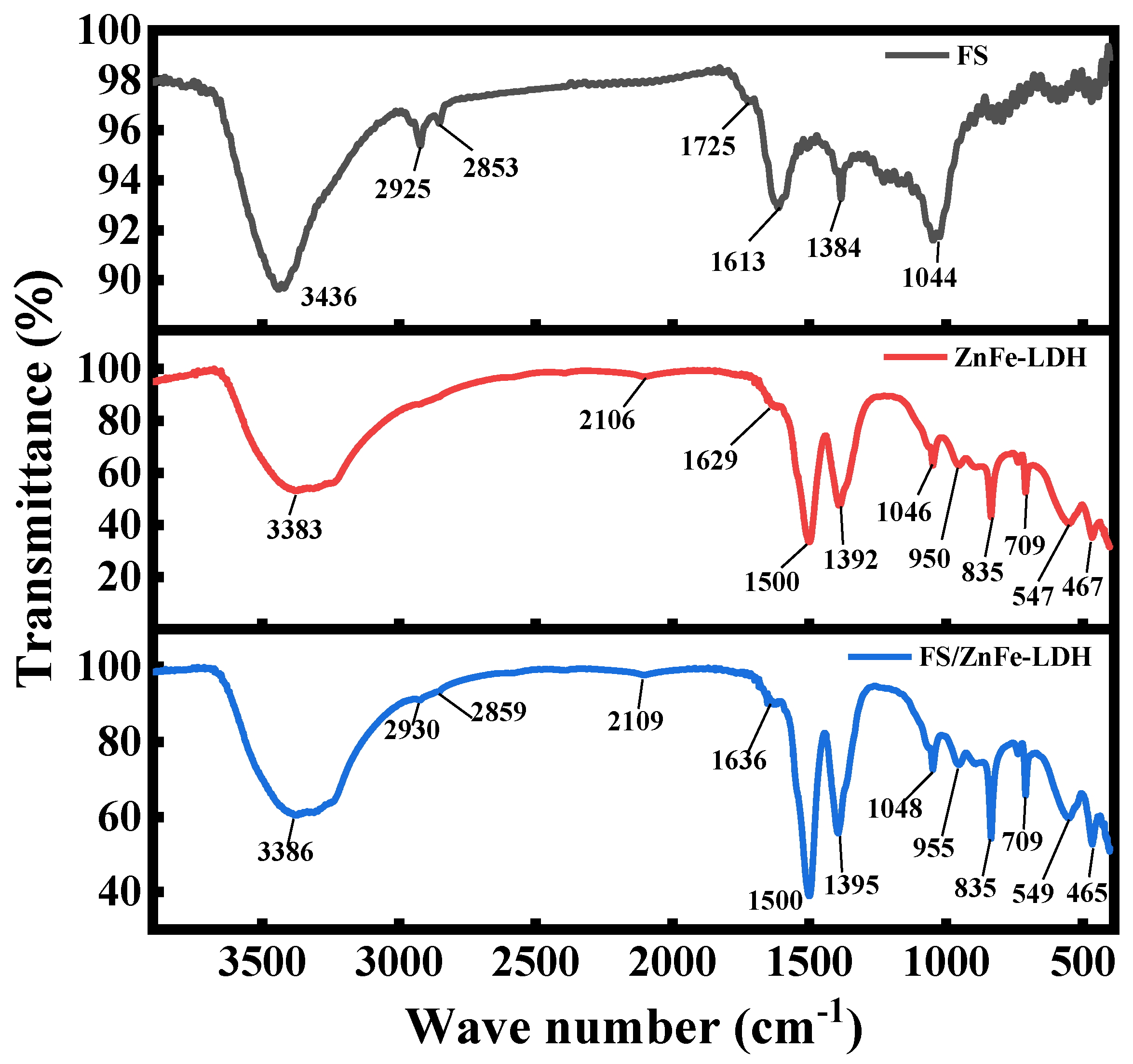
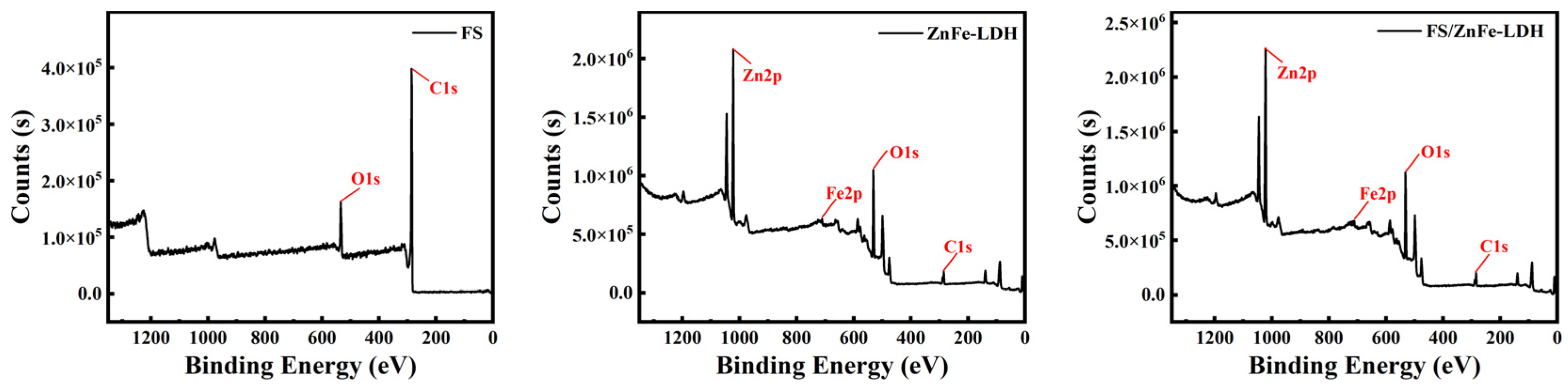
3.1. FTIR and XPS Analysis

As we can see from the infrared spectra of the three lubricating materials in Figure 1 that the characteristic peaks of ZnFe-LDH and FS/ZnFe-LDH are very similar. However, FS is very different from ZnFe-LDH and FS/ZnFe-LDH, which indicates that the functional groups of ZnFe-LDH and FS/ZnFe-LDH are basically the same but distinct from FS. The hydroxyl C-OH was associated with the characteristic peak near 3400 cm in Figure 1. For the two materials FS and FS/ZnFe-LDH, the peaks of -CH2 bond were found at 2930 cm−1 and 2850 cm−1 separately. Moreover, for FS, the peak at 1725 cm−1 and 1613 cm−1 corresponded with the C=O bond (1725 cm−1) and the C=O bond on the aromatic ring (1613 cm−1). In the FS infrared spectrum, the peak that appears at 1384 cm−1 was caused by the C-H bond. The characteristic peak at 1044 cm−1 was assigned to the ether bond C-O-C. In the infrared spectra of ZnFe-LDH and FS/ZnFe-LDH these two materials, the peak of the O-C-O bond is observed, which is in the range of 1500–1636 cm−1. The peak at 1395 cm−1 (1392 cm−1) was caused by the symmetrical stretching vibration of carbonate O-C-O in the ν3 modes [22], and a peak that confirmed the presence of zinc hydroxylation (Zn-OH) was found near 950 cm−1 [23]. The three peaks appearing in the range of 835–1048 cm−1 were carbonate stretching vibrations. The two peaks at 465–549 cm−1 are related to the metal-oxygen bond [24,25].
To investigate the differences in the elemental composition of the above three lubricating materials, the elemental valence composition of the three lubricating materials prepared was analyzed through XPS. Figure 2 shows the full spectrum of the three lubricating materials, FS, ZnFe-LDH, and FS/ZnFe-LDH, all discovered two elements of C and O. It is worth noting that, among them, ZnFe-LDH and FS/ZnFe-LDH detected the two elements Zn and Fe. To further distinguish them, the fine spectra of the above elements were fitted. Figure 3a,c,g shows the carbon element spectra of FS, ZnFe-LDH, and FS/ZnFe-LDH, respectively. The C-C bond, which is used for charge correction, is shown by the peak at 284.8 eV. The characteristic peak of 286.28 eV in the carbon element spectrum of FS is attributed to C-O-C or C=O; For the carbon spectra of ZnFe-LDH and FS/ZnFe-LDH, in Figure 3c,g, the peaks appearing at 289.47 eV and 289.33 eV are related to carbonate hydroxides [26]. Figure 3b,d,h shows the oxygen element spectra of the three lubricating materials, respectively. For FS, the peaks of C-O and C=O appear at 531.8 eV and 533.81 eV, respectively. The characteristic peaks appearing at around 529.6 eV in the oxygen spectrum of ZnFe-LDH and FS/ZnFe-LDH are assigned to metal oxides (Zn-O, Fe-O) [27]. In Figure 4d,h, the peak at about 531.7 eV corresponds to the existence of surface defects in ZnFe-LDH and FS/ZnFe-LDH, in the form of oxygen vacancies [28]. Figure 3e,i shows the zinc element spectra of ZnFe-LDH and FS/ZnFe-LDH, respectively. In Figure 3e,i, the two peaks corresponding to Zn2p3/2 and Zn2p1/2 appear near 1022 eV and 1045 eV, respectively [29]. Figure 3f,g shows the iron element spectra of ZnFe-LDH and FS/ZnFe-LDH, respectively. In the figure, characteristic peaks around 721 eV and 725 eV belong to Fe3+, the peaks around 718 eV belong to the satellite peaks of Fe2p3/2 [30]. The result of XPS analysis corresponds to the result of infrared spectrogram analysis.

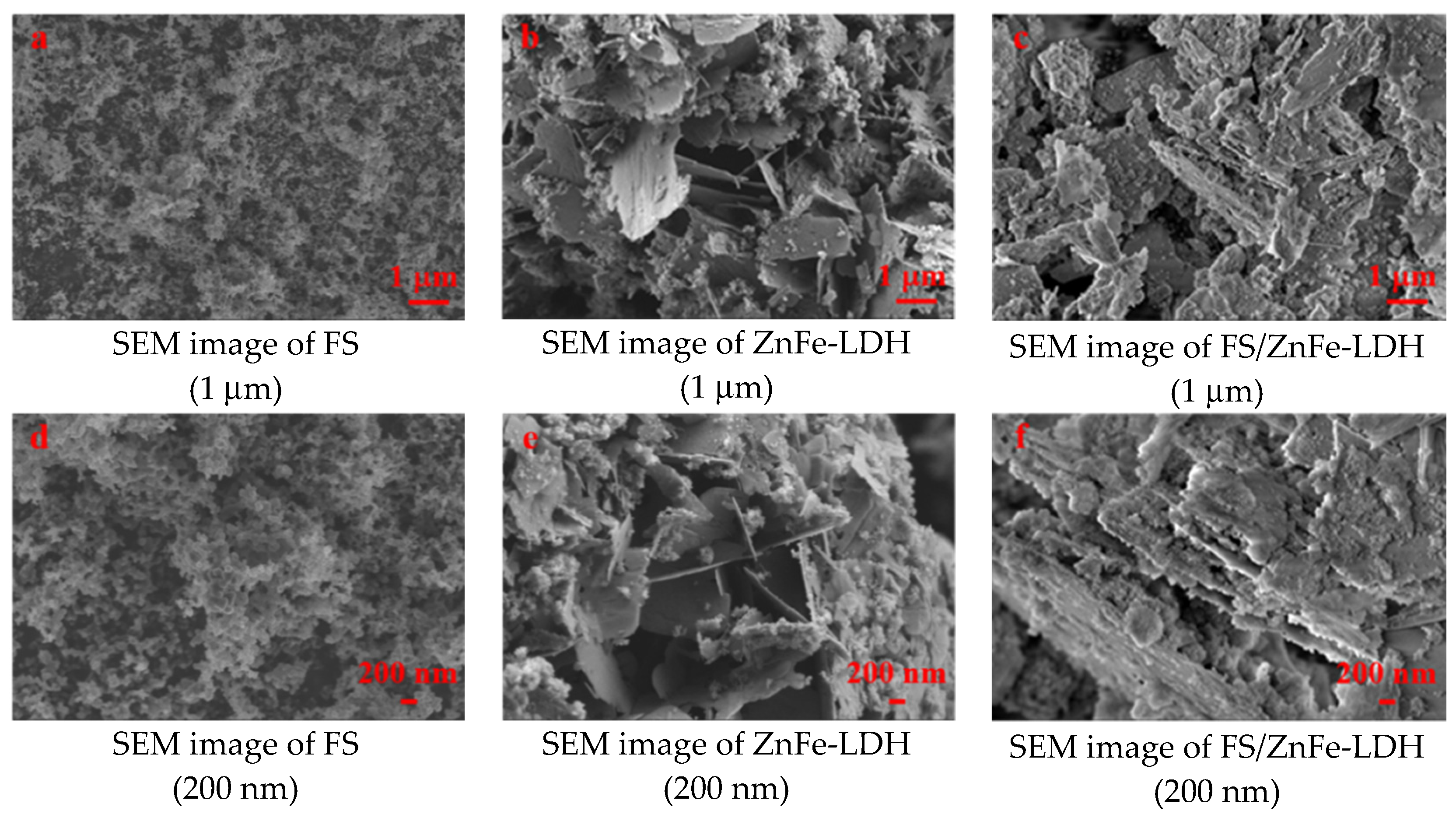
3.2. Structure Analysis and Surface Topography Analysis

The SEM images of the three lubricating materials are seen in Figure 4. Figure 4a,d is FS, Figure 4b,e is ZnFe-LDH, Figure 4c,f is FS/ZnFe-LDH. As we can see from Figure 4, FS is an agglomeration composed of spherical carbon particles, but ZnFe-LDH and FS/ZnFe-LDH consist of nanoplates and particles. Compared with FS/ZnFe-LDH, ZnFe-LDH can be observed as more dispersed nanoplatelets, while FS/ZnFe-LDH is a stacked layered structure of nanoplatelets, with some particles and soot filling in between the nanoplatelets.

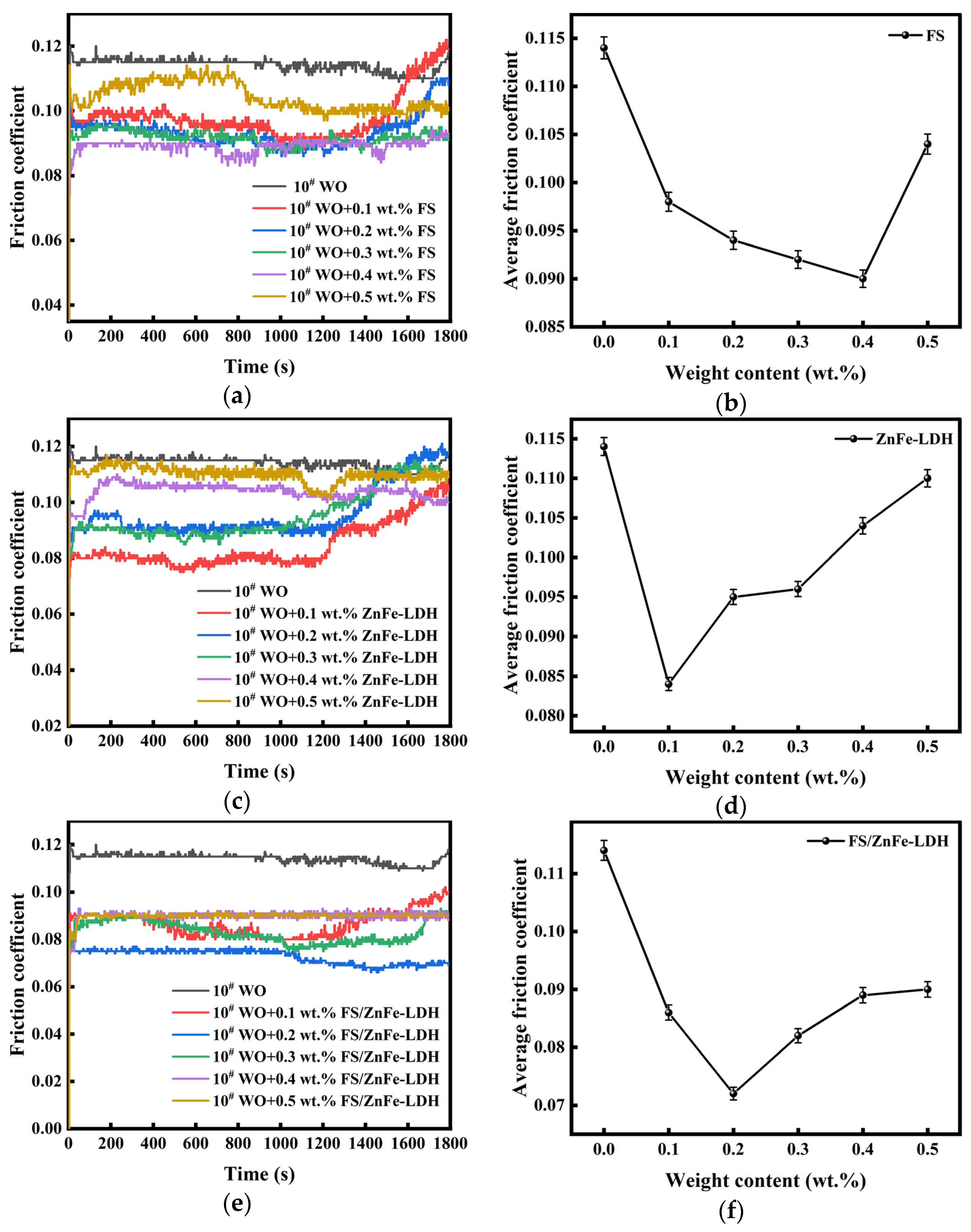
3.3. Influence of the Three Lubricating Materials on the Anti-Friction Performance of 10# WO

Figure 6a,c,e shows the friction coefficient (FC) variation with test time for the above three lubricating materials, respectively. Figure 6b,d,f shows the average friction coefficient (AFC) changes with the additional amount of the above three lubricating materials, respectively. As shown in Figure 6a,d, FS has a certain anti-friction effect. As the convergence of FS in base oil increases, the changing trend of FC appears to decrease and then increase. When the addition amount is 0.4 wt.%, the FC is the smallest but still fluctuates, and when the additional amount is increased to 0.5 wt.%, the FC rises sharply, and there is a big fluctuation. As a 10# WO additive, FS itself is a kind of agglomerate of carbon microspheres, prone to agglomeration in 10# WO. And when the added amount is large, the agglomeration of soot is more serious, making the anti-friction effect of FS ineffective, so the FC curve is unstable [31]. Figure 6a shows that when the FS content is 0.2 wt.%, the FC rises sharply after 1400 s. The reason for this is that FS has poor oil solubility and uneven dispersion in 10# WO. Figure 6b,c, the FC change diagram and AFC change diagram of ZnFe-LDH, shows that the friction reduction effect of ZnFe-LDH is limited. When the addition amount of ZnFe-LDH was 0.1 wt.%, the FC was the lowest. After adding ZnFe-LDH to 10# WO, it was found that the FC curves of all the added concentrations showed a sharp increase in FC after 1200 s. After the addition of ZnFe-LDH reached the minimum of 0.1 wt.%, the AFC continued to increase with the increase of the addition, but the highest AFC did not exceed the AFC of 10# WO. Analysis of the reason for this phenomenon is that ZnFe-LDH, as a material mainly composed of nanosheet, the limited dispersibility in the base oil makes its anti-friction effect unsatisfactory. Furthermore, it shows that when ZnFe-LDH is used as an additive of 10# WO, the added content should not be too high. From Figure 6e,f we see that compared with FS and ZnFe-LDH, the FC of each addition amount of FS/ZnFe-LDH is relatively lower, and the trend of AFC change is first to decrease and then increase. When the addition amount of FS/ZnFe-LDH was 0.2 wt.%, the AFC was the smallest, and the FC curve was relatively steadier without large fluctuations. The reason is that the unique “sandwich layer” structure of FS/ZnFe-LDH has played a role. Besides, FS/ZnFe-LDH added cetyltrimethylammonium bromide during the preparation process, and the surface was grafted with long carbon chains, which improved its oil solubility and dispersibility [32]. The AFC of 10# WO is 0.114, and the minimum AFCs of the three lubricating materials are 0.09, 0.084, and 0.072, respectively. Compared with 10# WO, the minimum AFC of the three lubricating materials was reduced by 21.05%, 26.32%, and 36.84%, respectively. FS/ZnFe-LDH has the largest reduction in AFC, which proves that the lubrication performance of FS/ZnFe-LDH is the best among the above three lubricating materials.

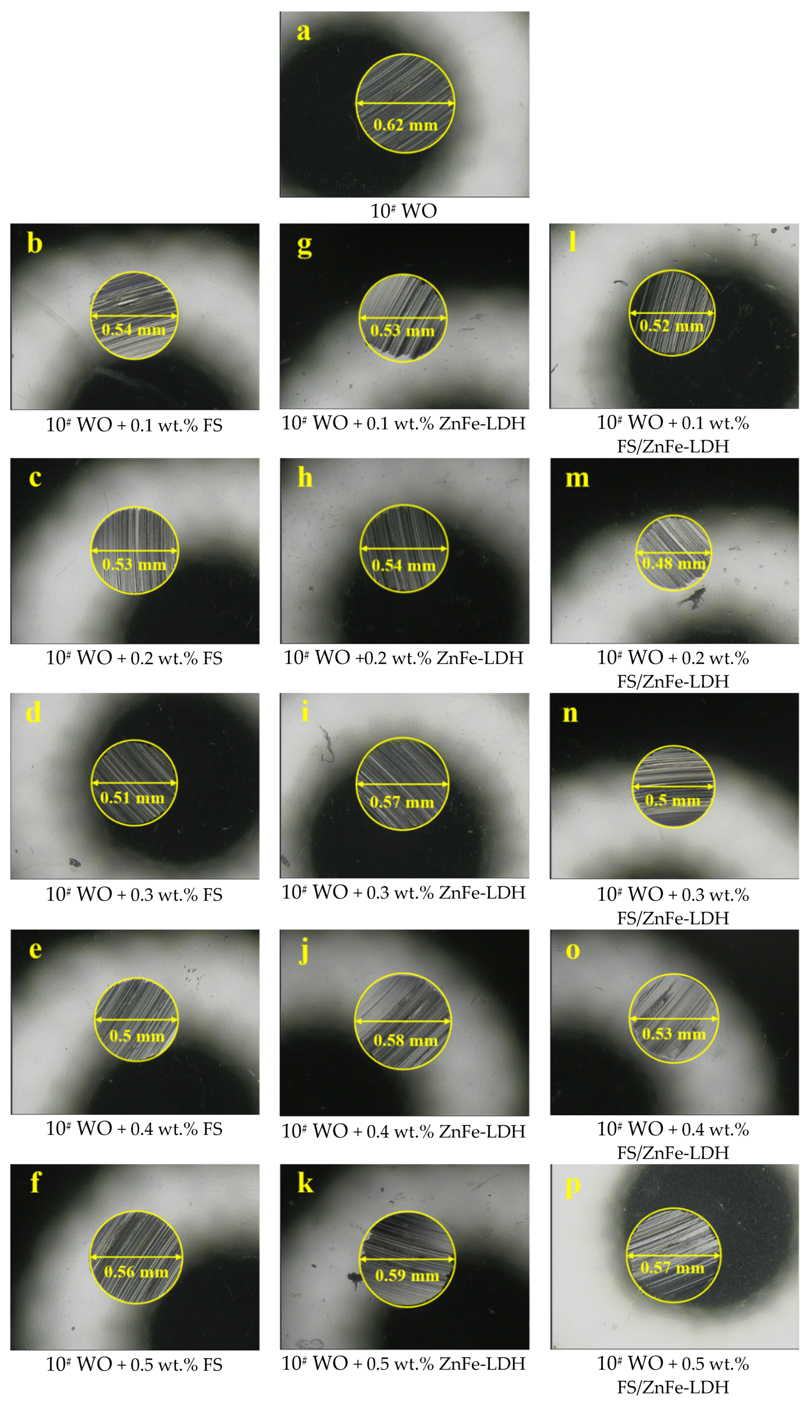
3.4. Influence of the Three Lubricating Materials on the Anti-Wear Properties of 10# WO

Figure 7a reveals the morphology of test ball wear scars under base oil, Figure 7b–f shows the morphologies of the lower test ball wear scars with different additions of FS, Figure 7g–k shows the morphologies of the lower test ball wear scars with different additions of ZnFe-LDH, and Figure 7l–p shows the morphologies of the lower test ball wear scars with different additions of FS/ZnFe-LDH.
As we can see from Figure 7 and Figure 8, the average wear scar diameter (AWSD) of 10# WO was 0.62 mm, and the AWSD after adding the above three lubricating materials were all less than the AWSD of 10# WO. With the increase of the above three lubricating materials additions, the AWSD changes showed different trends. The oil sample with FS added had a decreasing and subsequently increasing AWSD change pattern. The minimum value of AWSD (0.5 mm) was reached when 0.4 wt.% FS was added. The AWSD of ZnFe-LDH was a continuously increasing trend. The minimum AWSD (0.53 mm) was reached at the concentration of 0.1 wt.%, 14.52% less than pure 10# WO. The AWSD of FS/ZnFe-LDH presented a V-shaped change trend, first decreasing and then increasing. The minimum AWSD (0.429 mm) was reached at 0.2 wt.% when the addition amount was 0.2 wt.%, 22.58% lower than the AWSD of 10# WO. The changing trend of AWSD was consistent with the changing trend of AFC. ZnFe-LDH has a certain anti-wear effect, but as the added content increases, its anti-wear performance is weakened. The reason is that ZnFe-LDH has poor dispersibility in 10# WO. FS/ZnFe-LDH’s surface is grafted with long carbon chains and its unique “sandwich layer” structure, which makes FS/ZnFe-LDH possess the best anti-wear performance.

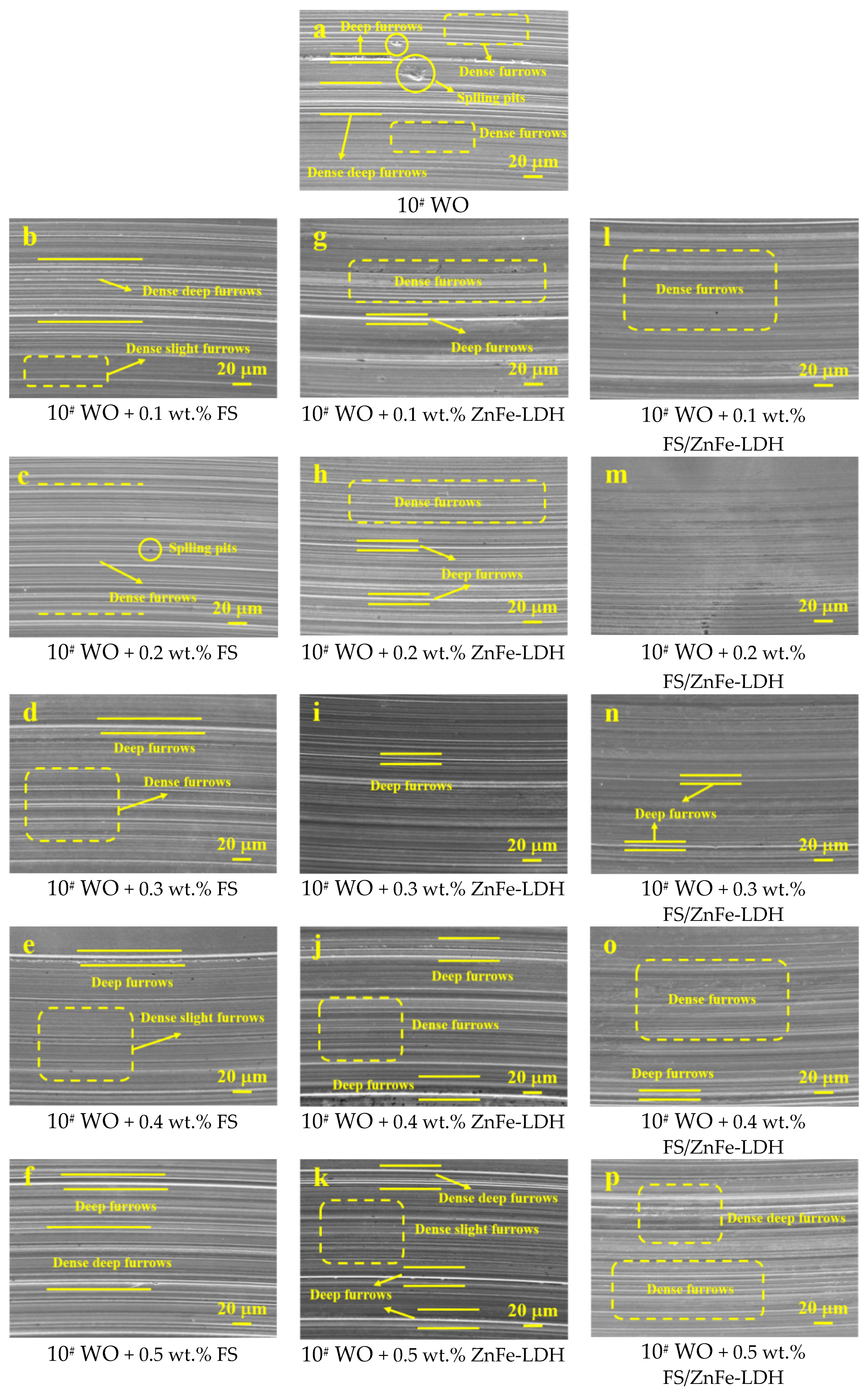
3.5. Analysis of Wear Scar Surface Morphology and Anti-Friction and Anti-Wear Mechanism

The wear scar on the steel ball was analyzed using SEM. The wear scar was magnified 1000 times to observe the wear condition of the steel ball surface. The wear scar morphology results are shown in Figure 9. As we can see from Figure 9, after adding the above three lubricating materials, the changing trend of the surface wear of the upper test ball was consistent with their respective AFC and AWSD change trends. The surface wear of FS decreases gradually as the addition amount decreases and then increases. The wear was the lightest when the amount of addition was 0.4 wt.%. The surface abrasion of ZnFe-LDH became more serious with the increase of the additional amount. However, the surface wear of FS/ZnFe-LDH gradually improved with the increase in the amount of addition, and then the wear intensified. The lightest wear occurred when FS/ZnFe-LDH was added at 0.2 wt.%.
Figure 9a shows the wear scars under 10# WO lubrication. As we can see from the figure, deep furrows with serious surface and shallow furrows are staggered and denser and deep furrows, along with larger spalling pits. Figure 9b–f shows the wear scars of the upper test ball with different added amounts of FS. We can see from the figure that when the FS addition amount is low, dense, deep furrows and some smaller spalling pits can be found on the surface. Moreover, by increasing FS addition amounts, the wear condition was improved, and the deep furrows were gradually reduced. When the addition amount of FS was 0.4 wt.%, the densely small furrows in the surface wear scars accounted for the majority. Dense and significant deep furrows reappeared when the amount of FS was increased to 0.5 wt.%. The reason is that when the FS content was too low, it was unable to build a homogeneous friction lubrication coating on the surface, resulting in serious wear. The main reason for the more serious wear when the added amount was too high is that FS agglomerates into large particles in the oil, which aggravates the wear. Figure 9g–k shows the surface wear scars of the upper test ball with different additions of ZnFe-LDH. As this shows, surface wear will gradually exacerbate with the increase in the addition amount. When the addition amount of ZnFe-LDH was 0.1 wt.%, the wear was relatively slight, and there were dense furrows and sporadic deep furrows on the surface. But when the additive amount gradually increased, the serious deep furrows on the surface gradually increased. When the addition of FS/ZnFe-LDH was increased to 0.5 wt.%, the deep furrows with dense wear scar surface accounted for the vast majority, and some serious furrows intersected. The analyzed reason is that the oil solubility of ZnFe-LDH is not very good, and the degree of crystallinity is high. ZnFe-LDH became abrasive particles during the friction process, which made densely deep furrows appear on the friction surface. Figure 9g–k shows the surface wear scars of the upper test ball with different additions of FS/ZnFe-LDH. As we can see, the surface wear of FS/ZnFe-LDH significantly improved compared with the other two additives, and the wear of each concentration is relatively slight compared to FS and ZnFe-LDH. When the addition amount was 0.1 wt.%, dense furrows appeared on the surface. In the wake of the increase of the FS/ZnFe-LDH addition amount, when the addition amount was 0.2 wt.%, only very shallow furrows existed on the surface. However, after the addition amount continued to increase, dense furrows reappeared, and the most severely dense furrows reappeared on the wear scar surface when the addition amount was 0.5 wt.%. Compared to the wear scar surface of pure white oil, FS, and ZnFe-LDH, the wear was relatively slight when the addition amount was 0.5 wt.%. The fundamental explanation for this is that FS/ZnFe-LDH disperses well in 10 WO due to its “sandwich layer” structure. Therefore, adding FS/ZnFe-LDH can make the wear ball test less abrasive.
XPS analysis was used to investigate the elemental composition of the wear scar. The purpose was to investigate further the similarities and differences of the above three lubricating materials as anti-friction and anti-wear mechanisms.
Figure 10a,d,g,j shows the C1s spectra of the four groups of steel ball surface wear scars. The peak corresponding to the C-C bond was detected at 284.8 eV. For Figure 10a,d, the peak at 288.63 eV and 288.53 eV correspond to the C-O bond or C=O bond. In Figure 10g,j, the peaks of the C-O bond, C=O bond, and metal carbonate were found at 288.66 eV and 288.52 eV. The peaks of the C-O-C bond emerge at 285.79 eV and 285.54 eV. A lubricating protective film forms on the surface of the wear scar as a result of the tribochemical reaction and adsorption that occurs during the friction process. This protective film is the main source of carbon.
Figure 10b,e,h,k shows the O1s spectra of the surface wear scars of the four groups of steel balls. Among them, the peaks appearing around 530.2 eV in Figure 10b,e shows characteristic peaks of Fe oxides, and the peaks appearing around 531.6 eV are characteristic peaks of the C-O bond or C=O. For Figure 10h,k, the characteristic peaks at 530.2 eV and 530.15 eV are assigned to the oxides of Fe and Zn. The source of the oxygen element is divided into two parts, one part comes from the lubricating protective film, and the other part comes from the oxidation of Fe. In Figure 10c,f,i,l, the Fe2p spectra of the four groups of steel ball surface wear scars, the peak of iron oxide emerges at 710.83–711.27 eV, the peaks appearing at 724.63–724.83 eV are the satellite peaks of iron oxide.
Differences between the 10# WO, FS, and Zn were also detected in the wear scars on the surface of the steel balls of the ZnFe-LDH and FS/ZnFe-LDH. The characteristic peaks in Figure 10m,n near 1022 eV and 1045 eV correspond to Zn2p3/2 and Zn2p1/2, separately [29], showing that the lubricating protective film formed on the surface wear scars of the above two sets of test balls not only contains the three elements of C, O, and Fe, but also contains Zn. Its source comes from adding ZnFe-LDH and FS/ZnFe-LDH in 10# WO.

4. Conclusions

  • FS is an agglomeration composed of amorphous carbon and graphite crystallite. ZnFe-LDH is mainly composed of Zn and Fe hydroxide nanosheets with a high degree of crystallinity. FS/ZnFe-LDH is a “sandwich layer” material composed of nanosheets and soot. FS/ZnFe-LDH may significantly improve the lubricating performance of 10# WO compared to FS and ZnFe-LDH.
  • The anti-friction and anti-wear capabilities of the three lubricating materials prepared were different. FS/ZnFe-LDH had the best lubrication performance, followed by FS, and finally ZnFe-LDH. FS/ZnFe-LDH has the “sandwich layer” structure, and the surface is grafted with long carbon chains that can improve oil solubility, so FS/ZnFe-LDH had the best lubrication performance.
  • In the friction process, FS/ZnFe-LDH participated in the formation of friction lubrication film, which contains the four elements C, O, Zn, and Fe. The friction surface was protected and repaired. Therefore, as a lubricant additive, FS/ZnFe-LDH effectively improves the lubricating performance of 10# WO.

Author Contributions

T.L. and J.W. conceived and designed the experiments. J.W. conducted experiments and analyzed the results. T.L. and J.W. wrote the paper. All authors have read and agreed to the published version of the manuscript.

Funding

This research was funded by the Natural Science Foundation of the Ningxia Hui Autonomous Region, grant number 2021AAC03181, and the Fundamental Research Funds for the Central Universities of the North Minzu University, grant number FWNX29.

Acknowledgments

The Ningxia low-grade resource high-value utilization and environmental chemical integration technology innovation team project.

Conflicts of Interest

The authors declare no conflict of interest.

References

  1. Song, L.L.; Cao, Z.; Dai, M. Material metabolism and carbon emission reduction strategies of passenger cars in China’s mainland. Resour. Sci. 2021, 43, 501–512. [Google Scholar] [CrossRef]
  2. Sun, W.C.; Jiang, M.Q. Coal-based synthetic fuel and its application and technical progress in automobile engines. J Automot. Saf. Energy 2021, 12, 1–17. [Google Scholar]
  3. Kang, K.; Liu, T.X.; Wang, J.; Qin, J. On the characteristic of Coal Fischer-Tropsch synthesis diesel soot. J. Henan Univ. (Nat. Sci.) 2021, 51, 75–82. [Google Scholar]
  4. Su, P.; Xiong, Y.; Liu, X.; Yang, H.; Fan, L.J.; Liu, P. The Role of Diesel Soot in the Tribological Behavior of 150SN Base Oil. China Pet. Process. Petrochem. Technol. 2017, 19, 89–95. [Google Scholar]
  5. Huang, G.W.; Yu, Q.L.; Ma, Z.F.; Cai, M.R.; Zhou, F.; Liu, W. Fluorinated Candle Soot as the Lubricant Additive of Perfluoropolyether. Tribol. Lett. 2017, 65, 28. [Google Scholar] [CrossRef]
  6. Hu, E.Z.; Hu, K.H.; Xu, Z.Y.; Hu, X.G.; Dearn, K.D.; Xu, Y.; Xu, Y.F.; Xu, L. Investigation into the morphology, composition, structure and dry tribological behavior of rice husk ceramic particles. Appl. Surf. Sci. 2016, 366, 372–382. [Google Scholar] [CrossRef] [Green Version]
  7. Hu, E.Z.; Hu, K.H.; Dearn, K.D.; Hu, X.G.; Xu, Y.F.; Yu, D.R.; Gu, H.M.; Tang, Y.C. Tribological performance of rice husk ceramic particles as a solid additive in liquid paraffin. Tribol. Int. 2016, 103, 139–148. [Google Scholar] [CrossRef] [Green Version]
  8. Hu, E.Z.; Dearn, K.; Yang, B.X.; Song, R.H.; Xu, Y.F.; Hu, X.G. Tribofilm formation and characterization of lubricating oils with biofuel soot and inorganic fluorides. Tribol. Int. 2017, 107, 163–172. [Google Scholar] [CrossRef]
  9. Guo, M.F.; Cai, Z.B.; Zhang, Z.C.; Zhu, M.H. Characterization and lubrication performance of diesel soot nanoparticles as oil lubricant additives. Rsc Adv. 2015, 5, 101965–101974. [Google Scholar] [CrossRef]
  10. Zhang, B.B.; Duan, J.Z.; Huang, Y.L.; Hou, B.R. Double layered superhydrophobic PDMS-Candle soot coating with durable corrosion resistance and thermal-mechanical robustness. J. Mater. Sci. Technol. 2021, 71, 1–11. [Google Scholar] [CrossRef]
  11. Su, F.H.; Chen, G.F.; Huang, P. Lubricating performances of graphene oxide and onion-like carbon as water-based lubricant additives for smooth and sand-blasted steel discs. Friction 2020, 8, 47–57. [Google Scholar] [CrossRef] [Green Version]
  12. Peng, J.F.; Shen, M.X.; Cai, Z.B. Nano Diesel Soot Particles Reduce Wear and Friction Performance Using an Oil Additive on a Laser Textured Surface. Coatings 2018, 8, 89. [Google Scholar] [CrossRef] [Green Version]
  13. Shi, B.; Guo, J.H.; Cao, X.A.; Hu, E.Z.; Hu, K.H. Effects of carbon soot from the combustion of diesel fuels on the tribological properties of lubricating oil and diesel fuels. Ind. Lubr. Tribol. 2018, 70, 532–537. [Google Scholar] [CrossRef]
  14. Li, S.; Bai, Z.; Zhao, D. Characterization and friction performance of Zn/Mg/Al-CO3 layered double hydroxides. Appl. Surf. Sci. 2013, 284, 7–12. [Google Scholar] [CrossRef]
  15. Li, G.J.; Zhang, Z.L.; Bai, Z.M. Friction performance of hydrotalcite as lubrication oil (grease) additive and its influence factors. J. Mater. Eng. 2021, 49, 48–55. [Google Scholar]
  16. Li, S.; Qin, H.; Zuo, R.; Bai, Z. Tribological performance of Mg/Al/Ce layered double hydroxides nanoparticles and intercalated products as lubricant additives. Appl. Surf. Sci. 2015, 353, 643–650. [Google Scholar] [CrossRef]
  17. Wang, K.; Wu, H.; Wang, H.; Liu, Y. Superior extreme pressure properties of different layer LDH nanoplatelets used as boundary lubricants. Appl. Surf. Sci. 2020, 530, 147203. [Google Scholar] [CrossRef]
  18. Wang, H.; Liu, Y.; Guo, F.; Sheng, H.; Xia, K.; Liu, W.; Wen, J.; Shi, Y.; Erdemir, A.; Luo, J. Catalytically Active Oil-Based Lubricant Additives Enabled by Calcining Ni-Al Layered Double Hydroxides. J. Phys. Chem. Lett. 2020, 11, 113–120. [Google Scholar] [CrossRef]
  19. Tsiganov, A.; Krivonogova, A.; Nikityuk, T.; Smirnova, O.; Gorokhovsky, A. Synthesis, structure and tribological properties of nanocomposite materials in the system of potassium polytitanate-layered double hydroxide–Serpentinite. In Proceedings of the 13th International Conference on Mechanical Engineering, Novosibirsk, Russia, 12–14 December 2019. [Google Scholar]
  20. Li, S.; Bhushan, B. Lubrication performance and mechanisms of Mg/Al-, Zn/Al-, and Zn/Mg/Al-layered double hydroxide nanoparticles as lubricant additives. Appl. Surf. Sci. 2016, 378, 308–319. [Google Scholar] [CrossRef]
  21. Ba, Z.W.; Han, Y.Y.; Qiao, D.; Feng, D.P.; Huang, G.W. Phoshate Interlayered LDH as Nanolubricant Additive. Tribology 2018, 38, 373–382. [Google Scholar]
  22. Aguilar, O.; Tzompantzi, F.; Pérez-Hernández, R.; Gómez, R.; Hernández-Gordillo, A. Novel preparation of ZnS from Zn5(CO3)2(OH)6 by the hydro- or solvothermal method for H2 production. Catal. Today 2017, 287, 91–98. [Google Scholar] [CrossRef]
  23. Parveen, M.F.; Umapathy, S.; Dhanalakshmi, V.; Anbarasan, R. Synthesis and Characterization of Nano-sized Zn(OH)(2) and Zn(OH)(2)/PVA Nano-composite. Compos. Interfaces 2010, 17, 757–774. [Google Scholar] [CrossRef]
  24. Tzompantzi-Flores, C.; Cesar Castillo-Rodriguez, J.; Gomez, R.; Tzompantzi, F.; Perez-Hernandez, R.; De la Luz Tlapaya, V.; Eduardo Santolalla-Vargas, C. Synthesis and characterization of ZnZr composites for the photocatalytic degradation of phenolic molecules: Addition effect of ZrO2 over hydrozincite Zn5(OH)6(CO3)2. J. Chem. Technol. Biotechnol. 2019, 94, 3428–3439. [Google Scholar] [CrossRef]
  25. Maria Rodriguez-Chiang, L.; Llorca, J.; Dahl, O.P. Effect of Fe-Zn-Mg-Al hydrotalcites on the methane potential of synthetic sulfate-containing wastewater. J. Water Process Eng. 2016, 10, 120–127. [Google Scholar] [CrossRef] [Green Version]
  26. Jing, Y.; Zhou, X.; Lund, P.; Chen, C.; Fan, L. Electrochemical impact of the carbonate in ceria-carbonate composite for low temperature solid oxide fuel cell. Int. J. Hydrogen Energy 2021, 46, 9898–9904. [Google Scholar] [CrossRef]
  27. Li, Q.; Wei, G.; Yang, Y.; Li, Z.; Zhang, L.; Huang, Q. Mechanochemical synthesis of Fe2O3/Zn-Al layered double hydroxide based on red mud. J. Hazard. Mater. 2020, 394, 122566. [Google Scholar] [CrossRef]
  28. Pooladi, M.; Shokrollahi, H.; Lavasani, S.A.N.H.; Yang, H. Investigation of the structural, magnetic and dielectric properties of Mn-doped Bi2Fe4O9 produced by reverse chemical co-precipitation. Mater. Chem. Phys. 2019, 229, 39–48. [Google Scholar] [CrossRef]
  29. Yuan, X.; Li, W. Graphitic-C3N4 modified ZnAl-layered double hydroxides for enhanced photocatalytic removal of organic dye. Appl. Clay Sci. 2017, 138, 107–113. [Google Scholar] [CrossRef]
  30. Wu, Q.; Yang, H.; Kang, L.; Gao, Z.; Ren, F. Fe-based metal-organic frameworks as Fenton-like catalysts for highly efficient degradation of tetracycline hydrochloride over a wide pH range: Acceleration of Fe(II)/Fe(III) cycle under visible light irradiation. Appl. Catal. B-Environ. 2020, 263, 118282. [Google Scholar] [CrossRef]
  31. Salehi, F.M.; Morina, A.; Neville, A. The effect of soot and diesel contamination on wear and friction of engine oil pump. Tribol. Int. 2017, 115, 285–296. [Google Scholar] [CrossRef] [Green Version]
  32. Wei, J.X.; Yao, M.H.; Cai, M.R.; Zhou, F. Tribological Properties of Cetyltrimethyl Ammonium Bromide Modified Candle Soot as Effective Lubricant Additive in Oil. Tribology. 2014, 34, 428–436. [Google Scholar]
Figure 1. Fourier transform infrared spectrometer(FTIR) spectra of Zinc-iron hydrotalcite(ZnFe-LDH), FS/ZnFe-LDH, and F-T diesel soot (F-T DS, FS).
Applsci 12 00599 g001
Figure 2. X-ray photoelectron spectroscopy(XPS) survey spectra of ZnFe-LDH, FS/ZnFe-LDH, and FS.
Applsci 12 00599 g002
Figure 3. XPS fine spectra of ZnFe-LDH, FS/ZnFe-LDH, and FS. (a,b) FS; (cf) ZnFe-LDH; (gj) FS/ZnFe-LDH.
Applsci 12 00599 g003
Figure 4. Scanning electron microscope(SEM) diagram of ZnFe-LDH, FS/ZnFe-LDH, and FS. From the HRTEM images of the above three lubricating materials in Figure 5, we know that FS consists of a few graphite crystallites and amorphous carbon and that ZnFe-LDH and FS/ZnFe-LDH mainly consist of nanoflakes. The nanoflakes in ZnFe-LDH are well dispersed, and the lattice strips are relatively clear. The surface layer of the FS/ZnFe-LDH nanosheets has soot and particles attached, and the lattice strips are more disorderly. Based on the analysis of the results of SEM and HRTEM, the nanosheets of FS/ZnFe-LDH and soot form a unique “sandwich layer” structure when used as a 10# WO lubricant additive, with tribological properties perhaps better than FS and ZnFe-LDH.
Applsci 12 00599 g004
Figure 5. High Resolution Transmission Electron Microscope (HRTEM) diagram of ZnFe-LDH, FS/ZnFe-LDH, and FS.
Applsci 12 00599 g005
Figure 6. Friction coefficient and average friction coefficient diagram of ZnFe-LDH, FS/ZnFe-LDH, and FS. (a,b) FS; (c,d) ZnFe-LDH; (e,f) FS/ZnFe-LDH.
Applsci 12 00599 g006
Figure 7. The morphology of the lower test ball wear scars.
Applsci 12 00599 g007
Figure 8. Trend of average wear scar diameter.
Applsci 12 00599 g008
Figure 9. SEM diagram of ball wear scars.
Applsci 12 00599 g009
Figure 10. XPS diagram of wear scars (ac) 10# WO; (df) FS; (gi,m) ZnFe-LDH; (jl,n) FS/ZnFe-LDH.
Applsci 12 00599 g010
Table 1. Comparison table of physicochemical properties of Fischer-Tropsch synthetic diesel (F-T diesel) and 0# diesel. (0# means number 0).
Physicochemical PropertiesF-T Diesel0# DieselTest Standard
Density (kg/m3, 20 °C)773.2737.8GB/T 1884
Kinematic viscosity (mm2, 20 °C)3.5954.71GB/T 265
Closed flash point (mg/100 mL)78.555GB/T 261
Oxidation stability sediment2.02.5SH/T 0175
Distillation Range50% recycling
temperature
286.5273GB/T 6536
90% recycling
temperature
335.0339
95% recycling
temperature
347.0355
Sulfur content (mass fraction), mg/kg<1.00.81SH/T 0689
Acidity (calculated by KOH), mg/100 mLnot detected5.64GB/T 258
10% residual carbon after steaming (mass fraction), %not detected0.3GB/T 17144
Ash content (volume fraction), %not detected0.01GB/T 508
Copper sheet corrosion (50 °C, 3 h), grade1a1aGB/T 5096
Moisture (volume fraction), %nonetraceGB/T 260
Total pollutant content, mg/kg//GB/T 33400
Lubricity, wear scar diameter, µm346/SH/T 0765
Solidifying point, °C50GB/T 510
Condensation point, °C44SH/T 0248
Cetane value/57.6GB/T 386
Cetane Index7946GB/T 11139
Polycyclic aromatic hydrocarbon content (mass fraction), %773.2/SH/T 0606
Fatty acid methyl ester content (volume fraction), %//NB/SH/T 0916
Publisher’s Note: MDPI stays neutral with regard to jurisdictional claims in published maps and institutional affiliations.

