Abstract
The article presents the experimental study analysis results of the methane combustion efficiency in a high-enthalpy oxygen-containing flow (HOF) inside of constant cross-section channel, finite along the length. The range of initial HOF enthalpies was considered from 350 to 700 kJ/kg. The regularities of the HOF initial enthalpy influence on the methane combustion efficiency were obtained. The values of the fuel excess coefficient under which the maximum coefficients of methane combustion completeness in the HOF are realized were determined. The data obtained indicate the realization of transitional diffusion-kinetic modes of methane combustion and make it possible to assess the factors limiting the combustion process.
1. Introduction
The methane (CH4) and natural gas are among the most promising fuels for power plants in the energy and transport industries. This is a consequence of the high-energy capacity and manufacturability of CH4, its relatively low cost, the availability of a large amount of raw stock and the possibility of minimizing environmental pollution in comparison with other hydrocarbon fuels [1,2,3]. In the methane combustion products, a high ratio of the water vapor mass fraction to the carbon dioxide mass fraction gH2O/gCO2 is realized. This reduces the formation of carbon-black on the elements of the power plants relative to the use of other hydrocarbons as fuel. However, ensuring the efficient methane combustion is a complex scientific and technical problem, which is determined by its low oxidation rate and the short concentration range of CH4 stable combustion with an air [4,5,6,7,8,9,10].
To search for methods of organizing efficient CH4 combustion, fundamental, and applied studies are being carried out on the chemical and physical intensification of diffusion and kinetic processes during the interaction of methane with oxygen-containing flows.
As a method of methane combustion chemical intensification, the addition of more active components, such as hydrogen or ethylene, can be considered. The studies [11,12,13,14,15,16,17,18,19,20] show that the addition of hydrogen allows us to shorten the length of the reaction zone and increase the combustion intensity at the flame foundation due to the combustion rate increase. It is noted that an increase in the hydrogen proportion leads to an increase in the OH radical concentration and to a decrease in the CO and NOx radicals in the combustion products. The addition of ~40% hydrogen (by volume) leads to increase the coefficient of methane combustion completeness approximately by 20% [12,13,14,15]. According to the studies [16,17], the flow turbulization which accompanying the hydrogen addition, increases the average flame propagation velocity in a multicomponent medium. The effects of the diffusion-thermal instability occurrence, as well as an increase in the mixture reactivity due to hydrogen addition to the turbulent flow, were also confirmed by numerical simulation [18,19,20]. The similar effects can be obtained due to ethylene addition to the methane [21,22,23], however, mixtures of methane with ethylene have a lower explosion capability.
A widespread method of methane combustion physical intensification, especially at high rates, is the eddy zones organization [24,25,26]. The eddy zones are realized in special niches, behind ledges or bluff bodies and make it possible to increase the local residence time of the mixture, which ensures combustion stabilization. The studies [27,28,29] show that nonstationary eddy zones increase gas-dynamic losses and can cause the development of vibrational combustion. Considering this, the methane combustion stabilization methods, based on new physical principles, are being actively developed in recent times. Such methods include an acoustic [30,31,32,33,34] and electrical effects on flames [35,36,37,38,39]. Definitely, these methods of intensification are promising, however, they require detailed research and testing.
It should be noted that one of the most technologically advanced methods for fuel combustion intensification is preliminary heating of the oxidizer [40], which can be carried out in special heat exchangers. Given the low reactivity, heating (enthalpy increasing) of the oxidizer can significantly improve the methane combustion efficiency. It is worth noting that nowadays the enthalpy of the oxidizer is often limited to ~700 kJ/kg in practice, which is determined by the maximum allowable heating temperature in known industrial heat exchangers.
A large number of experiments on methane combustion at elevated enthalpies are conducted in smaller laboratory facilities [41,42]. Some of the data presented were obtained by methane combustion in the presence of water vapor or other inhibitory additives, which should be taken into account during their analysis. It should also be pointed out that the data obtained in low-sized laboratory facilities are of limited use due to the difference in mixing and turbulence parameters from full-scale values. Some studies describing the air enthalpy effect on methane combustion under conditions as close as possible to natural conditions are presented in studies [42,43,44,45,46,47,48]. In particular, in the study [48] the issues of methane combustion in a short combustion chamber were investigated with the parameters of the air flow at the inlet, corresponding to the Mach number M = 2, the total pressure p0 = 3.6 ÷ 7.6 bar, and the air stagnation temperature T*= 690 ÷ 910 K. The configuration of the combustion chamber, the methane injection system, and combustion modes investigated in the study [48] have the specific features related to the organization of a nonuniform supersonic flow at the inlet, heating of the methane (up to 880 K temperatures), gas-dynamic throttling of the flow and the organization of combustion stabilization behind the ledges. The fragmentary data on the establishment of methane combustion deflagration and detonation modes at high oxidizer temperatures are pointed out in studies [49,50,51]. Despite a large number of well-known publications, there are no systematic data on the methane combustion in a high-enthalpy turbulent oxygen-containing flow (HOF) at flow velocities of ~100 m/s. Besides studies mentioned above, the positive effect of temperature on the combustion stabilization is shown in study [52], but the data presented in it were obtained for temperatures over 1500 K.
Considering the above, the main task of this study is to conduct parametric experimental studies and analyze the obtained regularities to reveal the unheated methane combustion efficiency in a high-enthalpy (up to 700 kJ/kg) oxygen-containing flow (HOF).
2. Experimental Facility and Data Processing Technique
Taking into account the multistage nature of physical and chemical processes, it is advisable to study the efficiency of methane combustion in a HOF using a facility with oxidative reactions realization in a constant cross-section channel [53,54]. In this study, the tests were carried out on an experimental facility, the scheme of which is shown in Figure 1. The experimental facility consists of a heat exchanger (1), a rectifying element (2), a crossover joint (3), the methane supply pylons (4), a constant cross-section channel (5), a throttler (6), and a longitudinal force sensor (7). The facility has five static pressure sampling points (8), a static pressure sampling point for fast processes registration (9), and the temperature measurement point (10) for the HOF enthalpy determination.
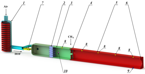
Figure 1.
Experimental facility scheme. 1—heat exchanger; 2—rectifying element; 3—crossover joint; 4—methane supply pylons; 5—channel of constant cross–section; 6—throttler; 7—longitudinal force sensor; 8—static pressure sampling points; 9—pressure pulsations sampling point; 10—HOF temperature measurement point.
Let us consider the operating principle of the experimental facility. The oxygen-containing flow (air) passing through the duct of the ohmic type heat exchanger (1) heats to the required enthalpy values. After the heat exchanger, the high-enthalpy oxygen-containing flow (HOF) passes through the rectifying element (2) and the crossover joint (3) to ensure the uniformity of the velocity, pressure and temperature fields at the input to the constant cross-section channel (5). The rectifying element is made on the honeycomb straightener principle with a characteristic transverse cell size of 5 mm and a length of 20 mm.
The channel (5) has a square cross-section with an area of 0.01 m2 and 10-fold elongation. The structural elements (pylons) with fuel injectors (4) with a diameter of ~0.8 mm, distributed evenly over the channel cross-section, are installed at the channel inlet. The relative number of injectors corresponds to 1600 m−2. The methane is supplied through the injectors, which ignites and combusts after its mixing with the high-enthalpy oxygen-containing flow. The ignition occurs using an electric-spark plug. At the outlet the throttler (6) is installed with an equivalent flow area of 3.9 × 10⁻³ m2, which is necessary to ensure the required velocity and pressure in the constant cross-section channel. The sensor (7) records the force generated by the output pulse of the methane combustion products flow with the HOF.
The static pressure registration was carried out by strain transducers with a frequency of 100 Hz. The measurement error is not more than ±0.25% of the upper measurement range. To measure pressure pulsations, high-frequency piezoelectric sensors with an operating frequency range of up to 200 kHz were used. The signal from the sensors was received to the recorder-analyzer input, which allows to conduct real-time measurements and express analysis of pressure pulsations. The registration of pressure pulsation signals was carried out at a frequency of ~13.5 kHz, which made it possible to carry out frequency analysis in the range (0, …, 6.75) kHz.
One of the most significant indicators of the workflow efficiency is the combustion completeness coefficient [55]. Taking this into account, an important aspect of the methane combustion study in constant cross-section channel is the indirect measurement of the combustion completeness coefficient η. In this study, we used the approach which was previously described in [54].
The constant cross-section channel receives the HOF mass flow rate Ga and the methane mass flow rate Gf. The mass fractions of the components are related to the combustion completeness coefficient in accordance with the equations
where ga—the HOF mass fraction; gf—the methane mass fraction; gpc—the combustion products mass fraction; L0—the stoichiometric ratio of components; φ = (L0·Gf)/Ga—the fuel excess coefficient. It is assumed that the γ factor is equal to
The calculated dependence of the force acting on the experimental facility from the combustion completeness coefficient was determined by solving the equations of energy, momentum and mass conservation for a mixture of HOF, methane and combustion products with the corresponding mass fractions ga, gf, and gpc.
The comparison of the calculated and experimental force values acting on the experimental facility makes it possible to determine the combustion completeness coefficient.
3. Experimental Results and Their Analysis
The studies were carried out for the range of HOF initial enthalpies H = 350, …, 700 kJ/kg. Four modes were selected and for each of them the fuel excess coefficient φ was varied in the range from 0.5 to 1.0. The pressure in the constant cross-section channel did not exceed 0.5 MPa in each of the modes, and the flow ratio to the channel area varied in the range from 130 to 140 kg/(s·m2) depending on the test mode.
The tests were carried out according to the test sequence diagram shown in Figure 2, which represents the dependence of the longitudinal force sensor readings (R) on time (t).
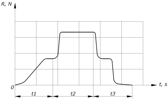
Figure 2.
Test sequence diagram.
At the t1 section of the test sequence diagram, the experimental facility output to a given mode is shown, heating of the HOF in a heat exchanger to a given temperature. At the t2 section, methane is supplied, which ignites and combusts in a constant cross-section channel. A sharp increase in the longitudinal force sensor readings is observed in this area. At the t3 section, the methane supply is completed and combustion stops. This process is accompanied by a sharp drop in the longitudinal force sensor readings and the HOF supply to the experimental facility stops.
Figure 3 represents the dependence of the reduced pressure p′, which is equal to the ratio of static pressure along the duct of constant cross-section channel p at the moment before the methane supply in the constant cross-section channel during the combustion of HOF and methane mixture to the maximum static pressure, realized during combustion from the reduced length of the constant cross-section channel L′ on one of the test modes.
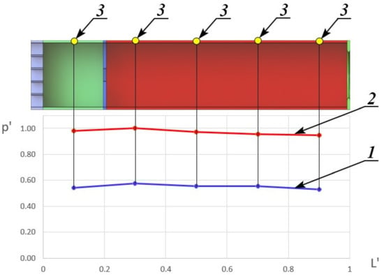
Figure 3.
Dependence of the reduced pressure on the reduced length. 1—without combustion; 2—with combustion; 3—static pressure sampling point.
As a result of the experimental data processing, the dependences of the combustion completeness coefficient on the fuel excess coefficient were obtained for different initial HOF enthalpies. The results are shown in Figure 4.
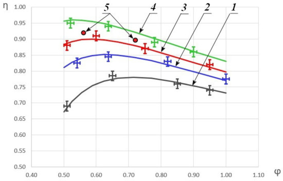
Figure 4.
Dependence of the combustion completeness coefficient on the fuel excess coefficient. 1—H = 360 kJ/kg; 2—H = 490 kJ/kg; 3—H = 580 kJ/kg; 4—H = 690 kJ/kg; 5—the data from the study [48] where H ≈ 580 kJ/kg.
The graph depicts the approximated dependences based on the obtained experimental data. As can be seen, with an increase in the initial HOF enthalpy, the combustion completeness coefficient increases and with an increase of the fuel excess coefficient, a monotonic increase in η to the some maximum is first observed. With a further decrease in φ, η begins to decrease as well. For comparison, the graph also shows some of the results from the study [48], which correlate fairly well with this study data. The differences in the combustion efficiency coefficients by 3–4% are due to the fact that the experiments in study [48] were carried out with not only air heating, but also a methane heating. In addition, in the current study, a constant cross-section channel was considered, and in study [48]—a channel with ledges, behind which recirculation zones are formed that stabilize combustion. It is worth noting that an increase in the enthalpy of the oxygen-containing oxidizer to 690 kJ/kg allows one to surpass the results previously published in study [48] without using additional measures to stabilize combustion, which leads to total pressure losses.
Figure 5 shows the dependence of the maximum values of combustion completeness coefficient ηmax on the initial enthalpy and the dependence of the combustion completeness coefficient η_1 on the initial enthalpy with fuel excess coefficient equal to φ = 1.
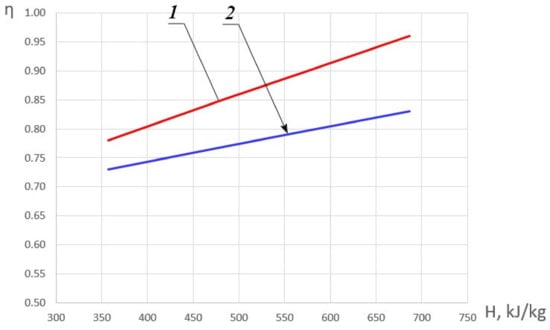
Figure 5.
Dependence of the combustion completeness coefficient on the initial HOF enthalpy. 1—ηmax; 2—η_1.
In the general case, an increase in enthalpy, as stated above, leads to an increase in the combustion completeness coefficient. In order to identify the combustion modes, let us assume that for φ < 1 with a positive value of the derivative ∂η/∂φ, a ‘kinetic’ mode of methane combustion is realized. In the area, for which ∂η/∂φ < 0, the ‘diffusion‘ mode of methane combustion becomes the most probable. In the case of the local maximum presence which is characterized by the equality-to-zero of the derivative ∂η/∂φ = 0, the combustion mode will be conventionally called ‘diffusion-kinetic’. The presence of an extremum can be explained by the influence of two mutually influencing factors: on the one hand, an increase in the fuel excess coefficient leads to a decrease in the oxygen concentration and on the other hand—to an increase in temperature. Moreover, with an increase in the HOF enthalpy, the position of this extremum shifts to the area of smaller values φ.
Based on the analysis of the experimental data obtained, φ were determined, under which the maximum values of the combustion completeness coefficient in the HOF are realized and ∂η/∂φ = 0. Let us call these φ values transitional. The results are shown in Figure 6. The figure also represents areas with predominantly kinetic and diffusion combustion modes.
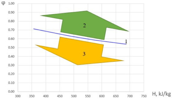
Figure 6.
Dependence of the fuel excess coefficient, corresponding to ∂η/∂φ = 0 on the initial HOF enthalpy (1), the area of the diffusion combustion mode (2), and the kinetic combustion mode (3).
The dependence of the transitional value of fuel excess coefficient in the considered range can be approximated by a following linear dependence: φ = 0.88 − 0.0005·H. When φ is less than the transitional value, the combustion mode is ‘kinetic’; and when it is greater, it is ‘diffusion’.
For further analysis, let us assume that the combustion completeness coefficient with a uniform flow in a constant cross-section channel can be represented as
where is the combustion completeness coefficient in the section with the longitudinal coordinate x, is the initial coefficient of methane combustion completeness (in the supply section). It should be noted that ≠ 0, since reverse currents occur during combustion in the fuel injection zone and methane is thrown ‘upstream’ [55,56].
By solving the system of equations for momentum, energy and flow rate conservation [57], it is possible to determine the relationship between the combustion completeness coefficient and the static pressure distribution
where K is the mapping coefficient, which depends on the thermophysical gas properties, the relational heat release during combustion and the gas-dynamic parameters of the flow. It should be noted that during combustion in a subsonic flow, K < 0, and during combustion in a supersonic flow K > 0.
According to the data obtained, for the considered flow modes in the experimental facility used, . In this case, with an increase of HOF enthalpy in the input the increases as well. This is a consequence of an increase in the chemical reactions rate with an increase in enthalpy and some changes of the reverse currents zone.
It is extremely important to analyze the dynamic processes during the methane combustion in constant cross-section channel. Thus, one of the main experimentally obtained parameters, which allow us to draw conclusions about the amplitude value and the dynamic processes frequency in a constant cross-section channel are the time realizations and spectrums of non-stationary pressure signals recorded during the tests. The analysis of the obtained data can provide new knowledge about the turbulent methane combustion and the occurrence of thermoacoustic instabilities.
To solve the assigned tasks, measurements of pressure pulsations were carried out in the experimental facility. The experiments have shown that the amplitudes of the spectral components Δp of gas oscillations in the channel have different values at each time instant. The study of dynamic processes can be based on the spectrogram analysis (Figure 7), which characterizes the dependence of the amplitude and pulsations frequency as a function of time. The spectrogram can trace the sequential transformation of the amplitude and pressure pulsations frequency at the each time instant of the experimental facility operation.
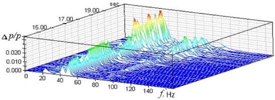
Figure 7.
Spectrogram of pressure pulsations in the experimental facility.
The signal spectrum of pressure pulsations in the experimental facility in the combustion mode contains a dominant discrete component at a frequency of f ≈ 43 Hz. In this case, the relative amplitude of pressure pulsations does not exceed 3.2%. This signal spectrum can correspond to two different oscillation processes caused by the combustion process. In the first case, sustained self-oscillations may occur [58], when the generation of vibrational energy due to the heat release process is compensated by its dissipation in the volume of a constant cross-section channel, as well as by the removal of acoustic energy through the boundary surfaces that limit its volume. The realization in time of such oscillatory process in a constant cross-section channel at a frequency f ≈ 43 Hz should have the form of a harmonic signal with a practically constant amplitude. In the second case, when the energy supplied due to the heat release process in the combustion mode in a constant cross-section channel is not enough to generate harmonic oscillations of constant amplitude, the time realization of the pressure pulsation signal at a frequency f ≈ 43 Hz should represent a harmonic signal with a randomly changing increasing and decreasing amplitude. This type of oscillation refers to a narrow-band random process [59]. As a result, it was found that the maximum values of the total relative amplitude of pressure pulsations for the test modes do not exceed 10%. This allows us to conclude that the combustion modes in a channel of constant cross-section are stable [60].
4. Conclusions
As a result of the methane combustion experimental study in a high-enthalpy oxygen-containing flow, a regularity of the initial enthalpy influence on the methane combustion efficiency was obtained. It was found that an increase in enthalpy from 350 kJ/kg to 700 kJ/kg leads to an increase in the combustion completeness coefficient up to 35%. The maximum value of combustion completeness coefficient in the considered experimental facility reaches 0.96.
It has been determined that the dependences of the combustion completeness coefficient in the considered experimental facility have extremums at φ = 0.72, …, 0.54. With an increase of the HOF enthalpy, the position of the extremum shifts to the area of smaller values φ. The dependence of the transition value of fuel excess coefficient from the HOF enthalpy was established: φ = 0.88 − 0.0005·H. When φ is less than the transition value, the combustion mode is ‘kinetic’; at the greater values, it is ‘diffusion’.
The analysis of dynamic processes have revealed that the maximum relative amplitudes of pressure pulsations reach the level of 3.2% and are realized at a frequency of 43 Hz.
Author Contributions
Conceptualization, K.A.; Writing—Original draft, I.G.; Writing—Review & editing, V.Z. All authors have read and agreed to the published version of the manuscript.
Funding
This research was supported by The Ministry of Science and Higher Education of the Russian Federation (agreement no. 075-15-2020-806 dated 29 September 2020).
Conflicts of Interest
The authors declare no conflict of interest.
References
- Urzay, J. Supersonic Combustion in Air-Breathing Propulsion Systems for Hypersonic Flight. Annu. Rev. Fluid Mech. 2018, 50, 593. [Google Scholar] [CrossRef]
- Tripathi, G.; Sharma, P.; Dhar, A. Effect of methane augmentations on engine performance and emissions. Alex. Eng. J. 2020, 59, 429. [Google Scholar] [CrossRef]
- Agora Energiewende; Ember. 2021: The European Power Sector in 2020: Up-to-Date Analysis on the Electricity Transition. Available online: https://static.agora-energiewende.de/fileadmin2/Projekte/2021/2020_01_EU-Annual-Review_2020/A-EW_202_Report_European-Power-Sector-2020.pdf (accessed on 15 December 2021).
- Azatyan, V.V. Chain nature of the combustion, explosion, and detonation of gases: New aspects of theory. Russ. J. Phys. Chem. A 2015, 89, 1731. [Google Scholar]
- Kim, N.J. Effect of an inlet temperature disturbance on the propagation of methane-air premixed flames in small tubes. Combust. Flame 2009, 156, 132. [Google Scholar] [CrossRef]
- Cheng, R.K. Autoignition in methane-hydrogen mixtures. Combust. Flame 1984, 58, 125. [Google Scholar] [CrossRef]
- Vasiliev, A.A. Ignition delay in multifuel mixtures. Combust. Explos. Shock Waves 2007, 43, 42. [Google Scholar] [CrossRef]
- Austin, J.M.; Shepherd, J.E. Detonations in Hydrocarbon Fuel Blends. Combust. Flame 2003, 132, 73. [Google Scholar] [CrossRef]
- Vasiliev, A.A. Cell size as the main geometric parameter of multifront detonation wave. J. Propul. Power 2006, 22, 1245. [Google Scholar] [CrossRef]
- Hernandez-Rivera, R.; Troiani, G.; Pagliaroli, T.; Hernandez-Guerrero, A. Detection of the thermoacoustic combustion instabilities of a slot burner based on a diagonal-wise recurrence quantification. Phys. Fluids 2019, 31, 124105. [Google Scholar] [CrossRef]
- Schefer, R.W.; Wicksal, D.M.; Agrawal, A.K. Combustion of hydrogen-enriched methane in a lean premixed swirl-stabilized burner. Proc. Combust. Inst. 2002, 29, 843–851. [Google Scholar] [CrossRef]
- Afarin, Y.; Tabejamaat, S. Effect of hydrogen on H2/CH4 flame structure of MILD combustion using the LES method. Int. J. Hydrogen Energy 2013, 38, 3447–3458. [Google Scholar] [CrossRef]
- Hernandez-Perez, F.E.; Groth, C.P.T.; Gulder, O.L. Large-eddy simulation of lean hydrogen-methane turbulent premixed flames in the methane-dominated regime. Int. J. Hydrogen Energy 2014, 39, 7147–7157. [Google Scholar] [CrossRef]
- Dinkelacker, F.; Manickam, B.; Muppal, S.P.R. Modelling and simulation of lean premixed turbulent methane/hydrogen/air flames with an effective Lewis number approach. Combust. Flame 2011, 158, 1742–1749. [Google Scholar] [CrossRef]
- Zhang, M.; Wanga, J.; Xie, Y.; Jin, W.; Wei, Z.; Huang, Z.; Kobayashi, H. Flame front structure and burning velocity of turbulent premixed CH4/H2/air flames. Int. J. Hydrogen Energy 2013, 38, 11421–11428. [Google Scholar] [CrossRef]
- Sun, Z.-Y.; Li, G.-X. Turbulence influence on explosion characteristics of stoichiometric and rich hydrogen/air mixtures in a spherical closed vessel. Energy Convers. Manag. 2017, 149, 526–535. [Google Scholar] [CrossRef]
- Sun, Z.-Y. Experimental studies on the explosion indices in turbulent stoichiometric H2/CH4/air mixtures. Int. J. Hydrogen Energy 2019, 44, 469–476. [Google Scholar] [CrossRef]
- Day, M.S.; Gao, X.; Bell, J.B. Properties of lean turbulent methane-air flames with significant hydrogen addition. Proc. Combust. Inst. 2011, 33, 1601–1608. [Google Scholar] [CrossRef]
- Therkelsen, P.L.; Enrique Portillo, J.; Littlejohn, D.; Martin, S.M.; Cheng, R.K. Self-induced unstable behaviors of CH4 and H2/CH4 flames in a model combustor with a low-swirl injector. Combust. Flame 2013, 160, 307–321. [Google Scholar] [CrossRef]
- Li, D.; Wang, R.; Yang, G.; Wan, J. Effect of hydrogen addition on the structure and stabilization of a micro-jet methane dif-fusion flame. Int. J. Hydrogen Energy 2021, 46, 5790–5798. [Google Scholar] [CrossRef]
- Liu, W.; Kelley, A.; Law, C. Flame propagation and counterflow nonpremixed ignition of mixtures of methane and ethylene. Combust. Flame 2010, 157, 1027–1036. [Google Scholar] [CrossRef]
- Wang, T.; Luo, Z.; Wen, H.; Cheng, F.; Liu, L.; Su, Y.; Liu, C.; Zhao, J.; Deng, J.; Yu, M. The explosion enhancement of methane-air mixtures by ethylene in a confined chamber. Energy 2021, 214, 119042. [Google Scholar] [CrossRef]
- Shao, J.; Davidson, D.F.; Hanson, R.K. A shock tube study of ignition delay times in diluted methane, ethylene, propene and their blends at elevated pressures. Fuel 2018, 225, 370–380. [Google Scholar] [CrossRef]
- Wilson, M.P.; Bowersox, R.D.W.; Glawe, D.D. Experimental Investigation of the Role of Downstream Ramps on a Supersonic Injection Plume. J. Propul. Power 1999, 15, 432. [Google Scholar] [CrossRef]
- Sislian, J.P.; Schumacher, J. Fuel/air mixing enhancement by cantilevered ramp injectors in hypersonic flows. In International Symposium on Air Breathing Engines (1999); American Institute of Aeronautics and Astronautics: Reston, VA, USA, 1999. [Google Scholar]
- Wan, J.; Zhao, H.; Akkerman, V. Anchoring mechanisms of a holder-stabilized premixed flame in a preheated mesoscale combustor. Phys. Fluids 2020, 32, 097103. [Google Scholar] [CrossRef]
- Chaudhuri, S.; Cetegen, B.M. Blowoff characteristics of bluff-body stabilized conical premixed flames with upstream spatial mixture gradients and velocity oscillations. Combust. Flame 2008, 153, 616. [Google Scholar] [CrossRef]
- Nair, S.; Lieuwen, T. Near-Blowoff Dynamics of a Bluff-Body Stabilized Flame. J. Propul. Power 2007, 23, 421. [Google Scholar] [CrossRef]
- Arefyev, K.Y.; Krikunova, A.I.; Panov, V.A. Experimental study of premixed methane-air flame coupled with an external acoustic field. J. Phys. Conf. Ser. 2019, 1147, 1. [Google Scholar] [CrossRef]
- Candel, S. Combustion dynamics and control: Progress and challenges. Proc. Combust. Inst. 2002, 29, 1–28. [Google Scholar] [CrossRef]
- Zong, R.; Kang, R.; Liu, C.; Zhang, Z.; Zhi, Y. Analysis of Flame Extinguishment and Height in Low Frequency Acoustically Excited Methane Jet Diffusion Flame. Microgravity Sci. Technol. 2018, 30, 237. [Google Scholar] [CrossRef]
- Bourehla, A.; Baillot, F. Appearance and stability of a laminar conical premixed flame subjected to an acoustic perturbation. Combust. Flame 1998, 114, 303. [Google Scholar] [CrossRef]
- Baillot, F.; Demare, D. Responses of a lifted non-premixed flame to acoustic forcing. Part 2. Combust. Sci. Technol. 2010, 179, 905–932. [Google Scholar] [CrossRef]
- Birbaud, A.L.; Durox, D.; Candel, S. Upstream flow dynamics of a laminar premixed conical flame submitted to acoustic modulations. Combust. Flame 2006, 146, 541–552. [Google Scholar] [CrossRef]
- Matsubara, Y.; Takita, K.; Masuya, G. Combustion enhancement in a supersonic flow by simultaneous operation of DBD and plasma jet. Proc. Combust. Inst. 2013, 34, 3287–3294. [Google Scholar] [CrossRef]
- Do, H.; Cappelli, M.A.; Mungal, M.G. Plasma assisted cavity flame ignition in supersonic flows. Combust. Flame 2010, 157, 1783–1794. [Google Scholar] [CrossRef]
- Leonov, S.B.; Kochetov, I.V.; Napartovich, A.P.; Sabel’Nikov, V.A.; Yarantsev, D.A. Plasma-Induced Ethylene Ignition and Flameholding in Confined Supersonic Air Flow at Low Temperatures. IEEE Trans. Plasma Sci. 2010, 39, 781–787. [Google Scholar] [CrossRef]
- Leonov, S.B.; Yarantsev, D.A.; Napartovich, A.P.; Kochetov, I.V.; Ignition, I.; Researcher, L. Plasma-Assisted Ignition and Flameholding In High-Speed Flow. In Proceedings of the 44th AIAA Aerospace Sciences Meeting Including the New Horizons Forum and Aerospace Exposition, Reno, NV, USA, 9–12 January 2006. [Google Scholar]
- Leonov, S.B.; Yarantsev, D.; Carter, C. Experiments on Electrically Controlled Flameholding on a Plane Wall in a Supersonic Airflow. J. Propuls. Power 2009, 25, 289–294. [Google Scholar] [CrossRef]
- Sosounov, V. Research and development of ramjets/ramrockets. Part III. The study of gaseous hydrogen ram combustors. AGARD Lect. Ser. 1993, 194, 1–6. [Google Scholar]
- Zhu, Q.; Zhao, X.; Deng, Y. Advances in the partial oxidation of methane to synthesis gas. J. Nat. Gas Chem. 2004, 13, 191–203. [Google Scholar]
- Mikofski, M.A.; Williams, T.C.; Shaddix, C.R.; Blevins, L.G. Flame Height Measurement of Laminar Inverse Diffusion Flames. Combust. Flame 2006, 146, 63. [Google Scholar] [CrossRef]
- Tsuji, H.; Gupta, A.K.; Hasegawa, T.; Katsuki, K.; Katsuki, M.; Morita, M. High Temperature Air Combustion: From Energy Conservation to Pollution Reduction; CRC Press: Boca Raton, FL, USA, 2003. [Google Scholar]
- Weber, R.; Orsino, S.; Verlaan, A.; Lallemant, N. Combustion of natural gas with high temperature air and large quantities of flue gas. Proc. Combust. Inst. 2000, 28, 1315. [Google Scholar] [CrossRef]
- Vinogradov, V.A.; Shikhman, Y.M.; Albegov, R.V.; Vedeshkin, G.K. Experimental Research of Methane Combustion in High Speed Subsonic Airflow. AIAA Paper 2002–5208—2002. In Proceedings of the 11th AIAA/AAAF International Conference Space Planes and Hypersonic Systems and Technologies, Orleans, France, 29 September–4 October 2002. [Google Scholar]
- Vinogradov, V.A.; Shikhman, Y.M.; Albegov, R.V.; Vedeshkin, G.K. About possibility of effective methane combustion in high speed subsonic airflow. AIAA Paper 2002–5206—2002. In Proceedings of the 11th AIAA/AAAF International Conference Space Planes and Hypersonic Systems and Technologies, Orleans, France, 29 September–4 October 2002. [Google Scholar]
- Xiao, W.; Huang, Y. Lean blowout limits of a gas turbine combustor operated with aviation fuel and methane. Heat Mass Transf. 2015, 52, 1015–1024. [Google Scholar] [CrossRef]
- Albegov, R.V.; Vinogradov, V.A.; Shikhman, Y.M. Combustion of methane injected into an air flow with high subsonic velocities by different methods. Combust. Explos. Shock Waves 2016, 52, 14–25. [Google Scholar] [CrossRef]
- Batraev, I.S.; Prokhorov, E.S.; Ul’Yanitskii, V.Y. Acceleration of Dispersed Particles by Gas Detonation Productions in an Expanding Channel. Combust. Explos. Shock Waves 2021, 57, 588–596. [Google Scholar] [CrossRef]
- Zipf, R.K.J.; Gamezo, V.N.; Sapko, M.J.; Marchewka, W.P.; Mohamed, K.M.; Oran, E.S.; Kessler, D.A.; Weiss, E.S.; Addis, J.D.; Karnack, F.A.; et al. Methane-Air Detonation Experiments at NIOSH Lake Lynn laboratory. J. Loss Prev. Process. Ind. 2013, 26, 281–396. [Google Scholar] [CrossRef]
- Aleksandrov, V.Y.; Arefyev, K.Y.; Baskakov, A.A.; Ilchenko, M.A. Detonation of air-methane mixture in a supersonic crossflow. BMSTU J. Mech. Eng. 2017, 2, 98–108. [Google Scholar] [CrossRef][Green Version]
- Arefyev, K.Y.; Aleksandrov, V.Y.; Rudinski, A.V. The investigation of the plasma effect on the gaseous methane combustion efficiency in a supersonic flow. High Temp. 2021, 59, 548–556. [Google Scholar]
- Guiberti, T.F.; Durox, D.; Scouflaire, P.; Schuller, T. Impact of heat loss and hydrogen enrichment on the shape of confined swirling flames. Proc. Combust. Inst. 2015, 35, 1385–1392. [Google Scholar] [CrossRef]
- Aref’ev, K.Y.; Kukshinov, N.V.; Serpinskii, O.S. Methodology of experimental determining the combustion efficiency of fuel mixture flows in channels of variable cross-section. Fluid Dyn. 2017, 52, 682–694. [Google Scholar] [CrossRef]
- Annushkin, Y.M. Basic laws of burn-out in turbulent hydrogen jets in air channels. Fiz. Goreniya Vzryva 1981, 4, 59. [Google Scholar]
- Aleksandrov, V.Y.; Kukshinov, N.V. Modified combustion efficiency curve for high-velocity model combustors inte-grated with the inlet. Combust. Explos. Shock Waves 2016, 52, 281–285. [Google Scholar]
- Aver’kov, I.S.; Aleksandrov, V.Y.; Aref’ev, K.Y.; Voronetskii, A.V.; Gus’kov, O.V.; Prokhorov, A.N.; Yanovskii, L.S. The influence of combustion efficiency on the characteristics of ramjets. High Temp. 2016, 54, 882–891. [Google Scholar] [CrossRef]
- Aref’Ev, K.Y.; Voronetskii, A.V.; Il’Chenko, M.A. Dynamic characteristics of a resonant gas-dynamic system for ignition of a fuel mixture. Combust. Explos. Shock Waves 2013, 49, 657–661. [Google Scholar] [CrossRef]
- Aref’Ev, K.Y.; Voronetskii, A.V.; Il’Chenko, M.A.; Suchkov, S.A. Numerical and experimental study of ignition of a two-phase fuel composition (ethanol + air) in a resonance gas-dynamic system. Combust. Explos. Shock Waves 2017, 53, 398–405. [Google Scholar] [CrossRef]
- Aleksandrov, V.Y.; Aref’Ev, K.Y.; Il’Chenko, M.A. Numerical and experimental study of oscillatory processes in small-size combustion heaters of air. Combust. Explos. Shock Waves 2016, 52, 439–445. [Google Scholar] [CrossRef]


Publisher’s Note: MDPI stays neutral with regard to jurisdictional claims in published maps and institutional affiliations. |
© 2022 by the authors. Licensee MDPI, Basel, Switzerland. This article is an open access article distributed under the terms and conditions of the Creative Commons Attribution (CC BY) license (https://creativecommons.org/licenses/by/4.0/).