
Analytical Analysis of the Groundwater Drawdown Difference Induced by Foundation Pit Dewatering with a Suspended Waterproof Curtain
Abstract
:1. Introduction
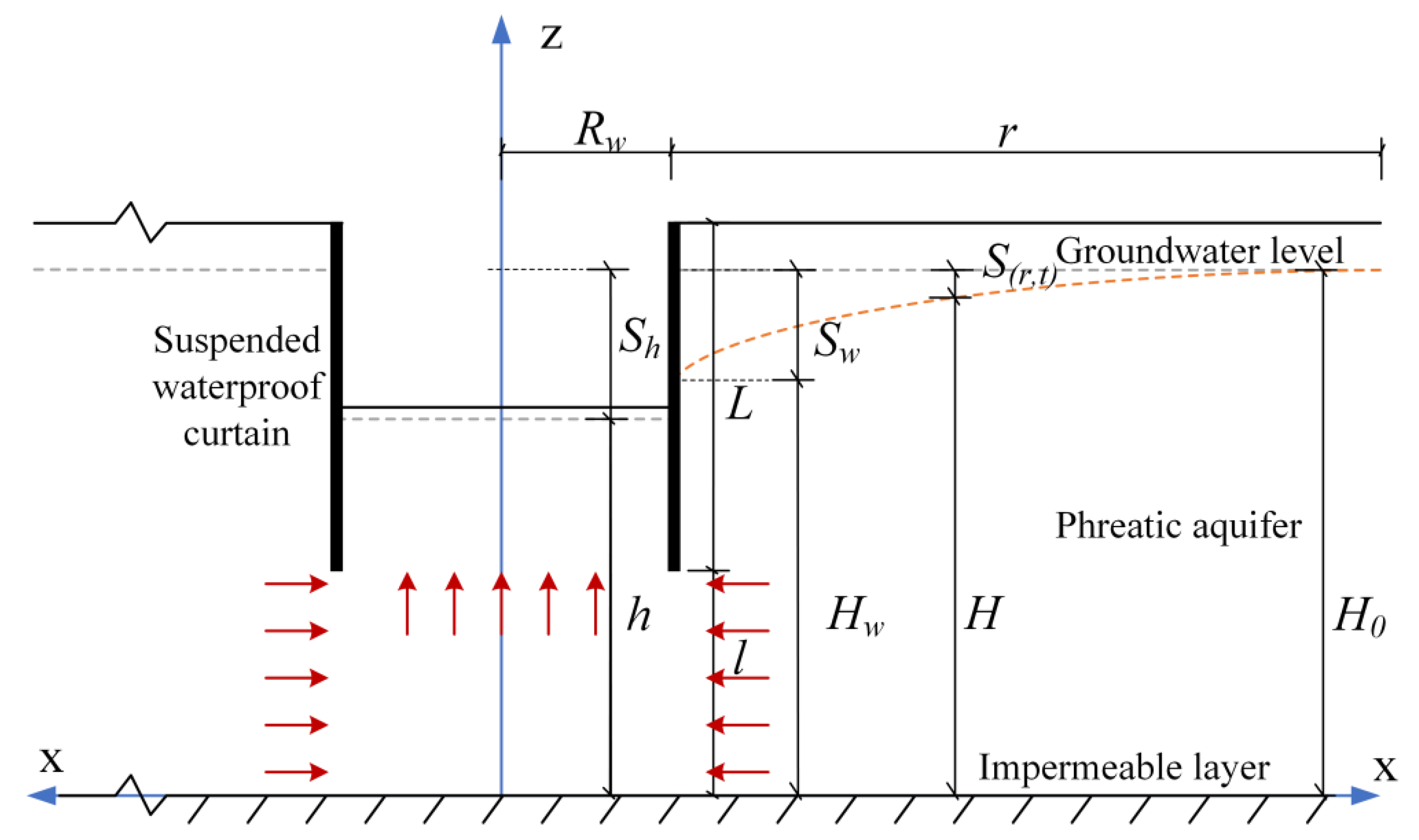
2. Dewatering with a Waterproof Curtain
3. Calculation of Groundwater Drawdown Difference
3.1. Methods and Assumptions
3.2. Modeling a Partially Penetrating Well
3.3. Modeling the Flow of Groundwater into the Foundation Pit
3.4. The Connection of the Groundwater Drawdown between Inside and Outside the Foundation pit
4. Model Validation
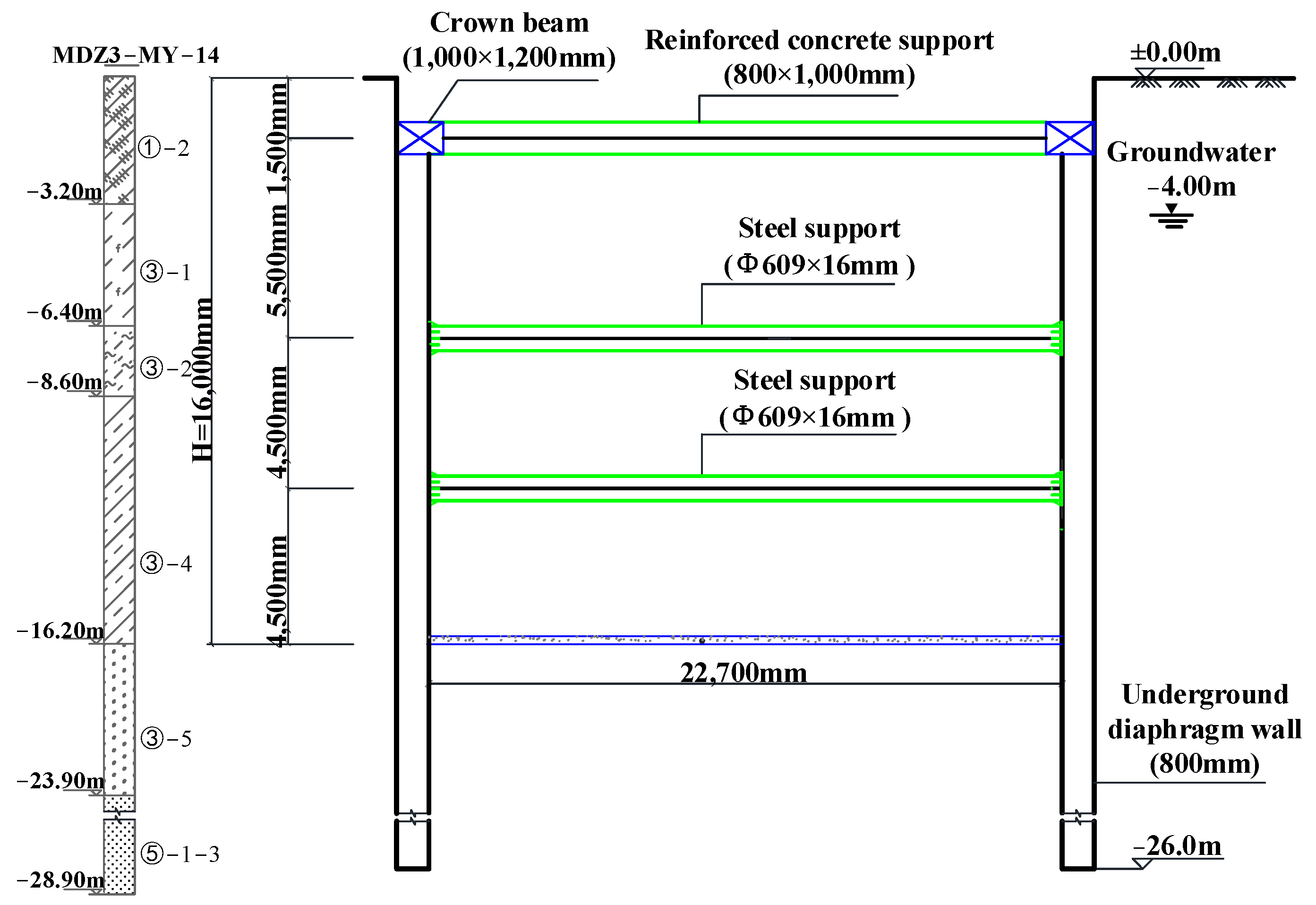
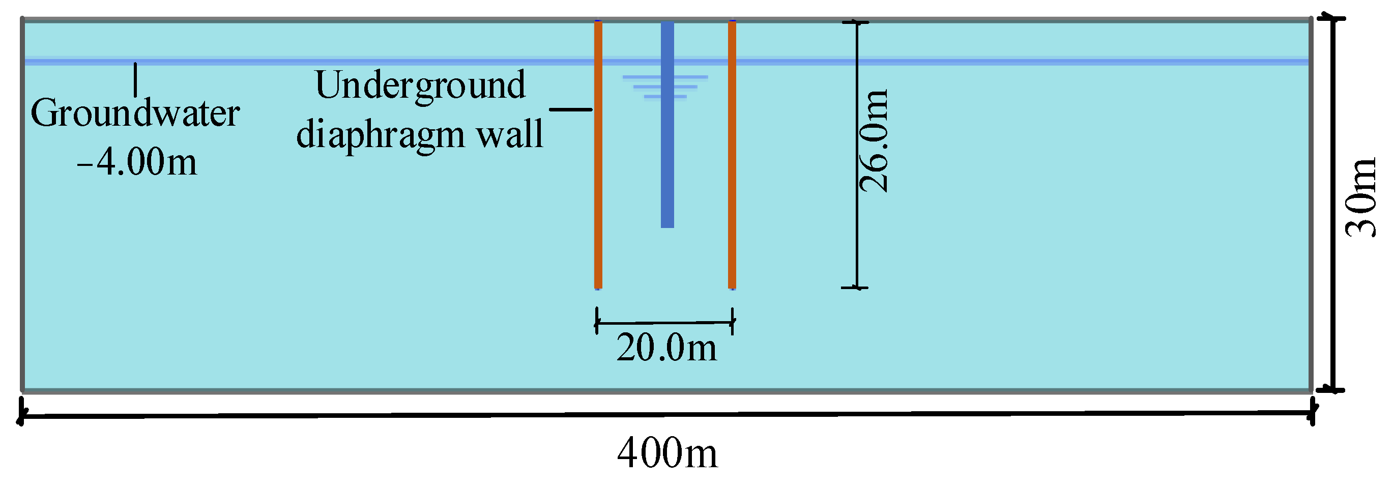
4.1. Project Information
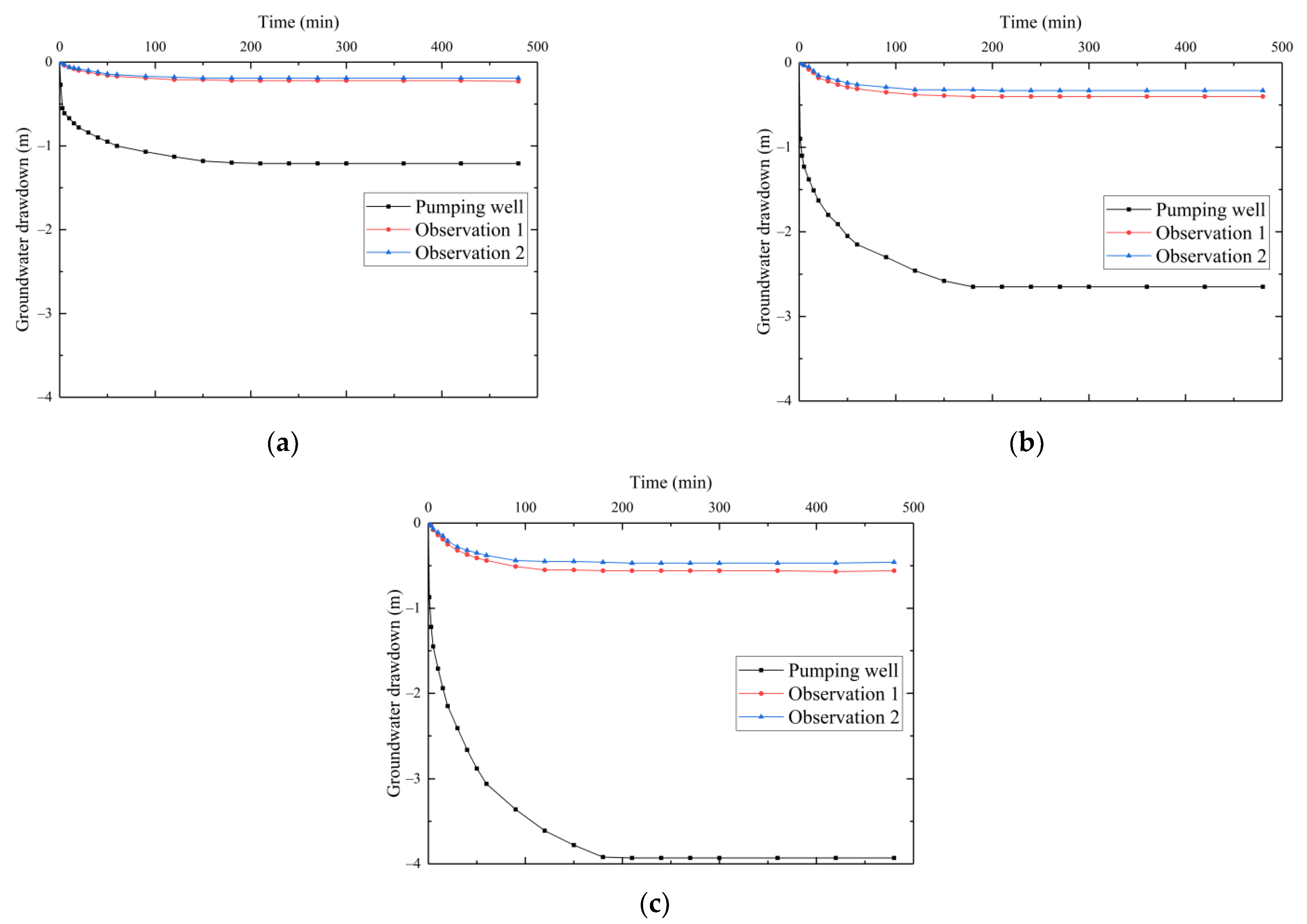
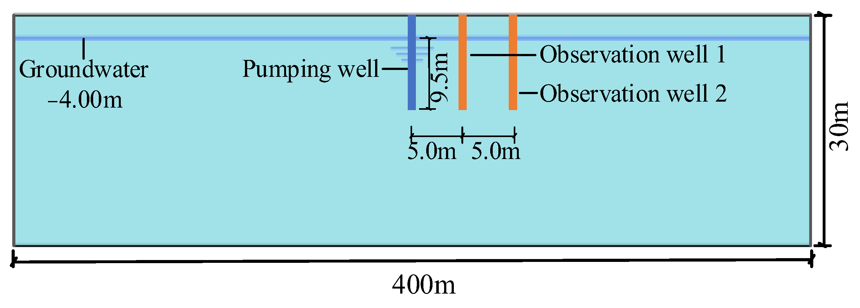
4.2. Pumping Test
4.3. FEM Model Setup
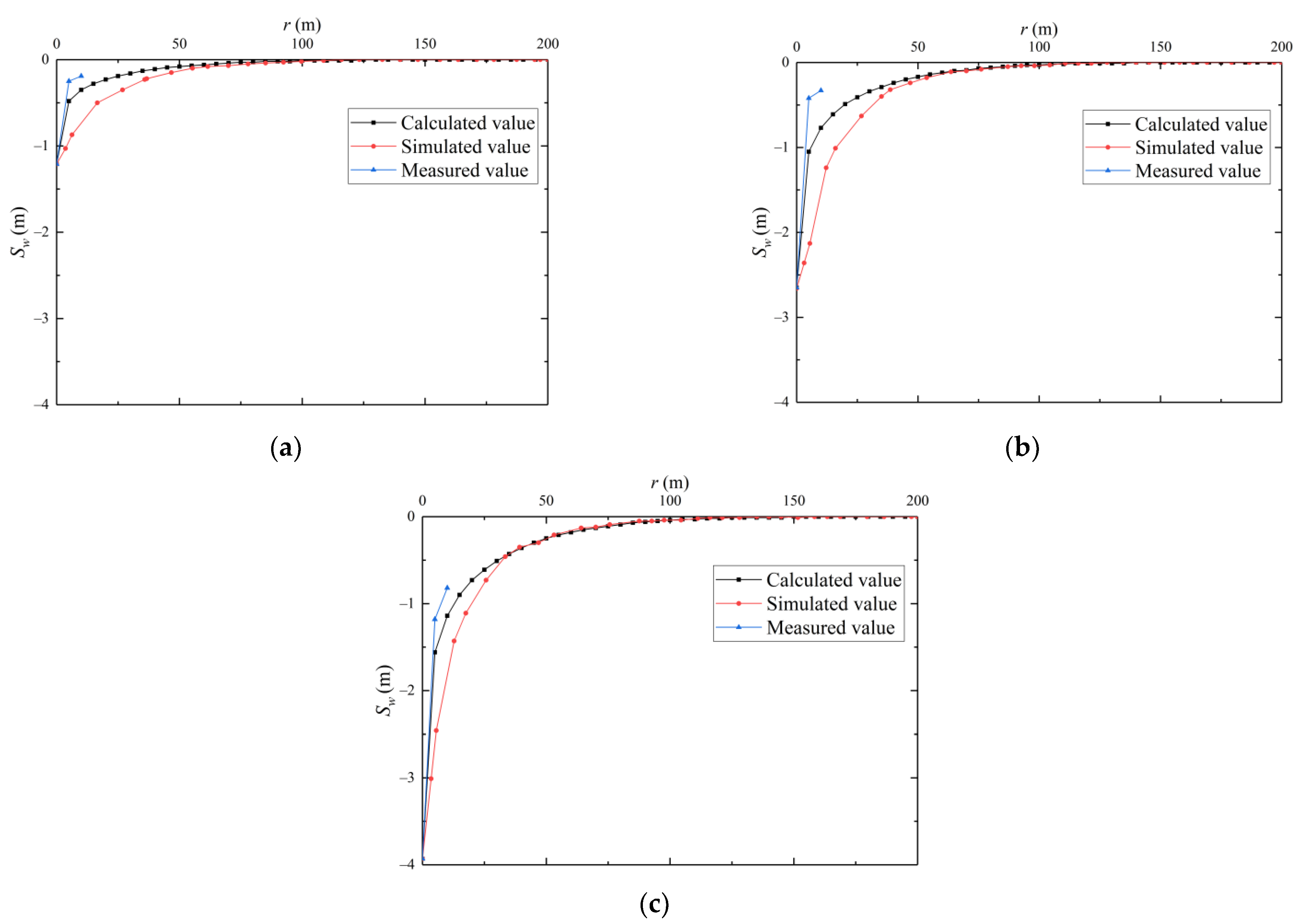
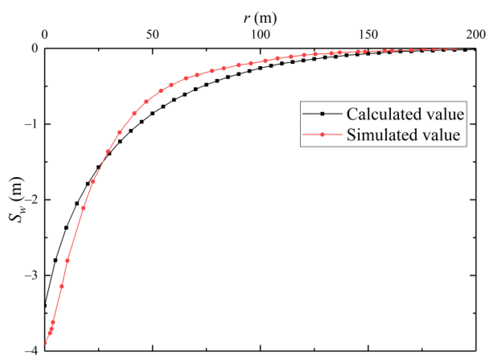
4.3.1. Validation of Groundwater Drawdown
4.3.2. Validation of Groundwater Drawdown Difference
5. Discussion on Sensitivity Parameters
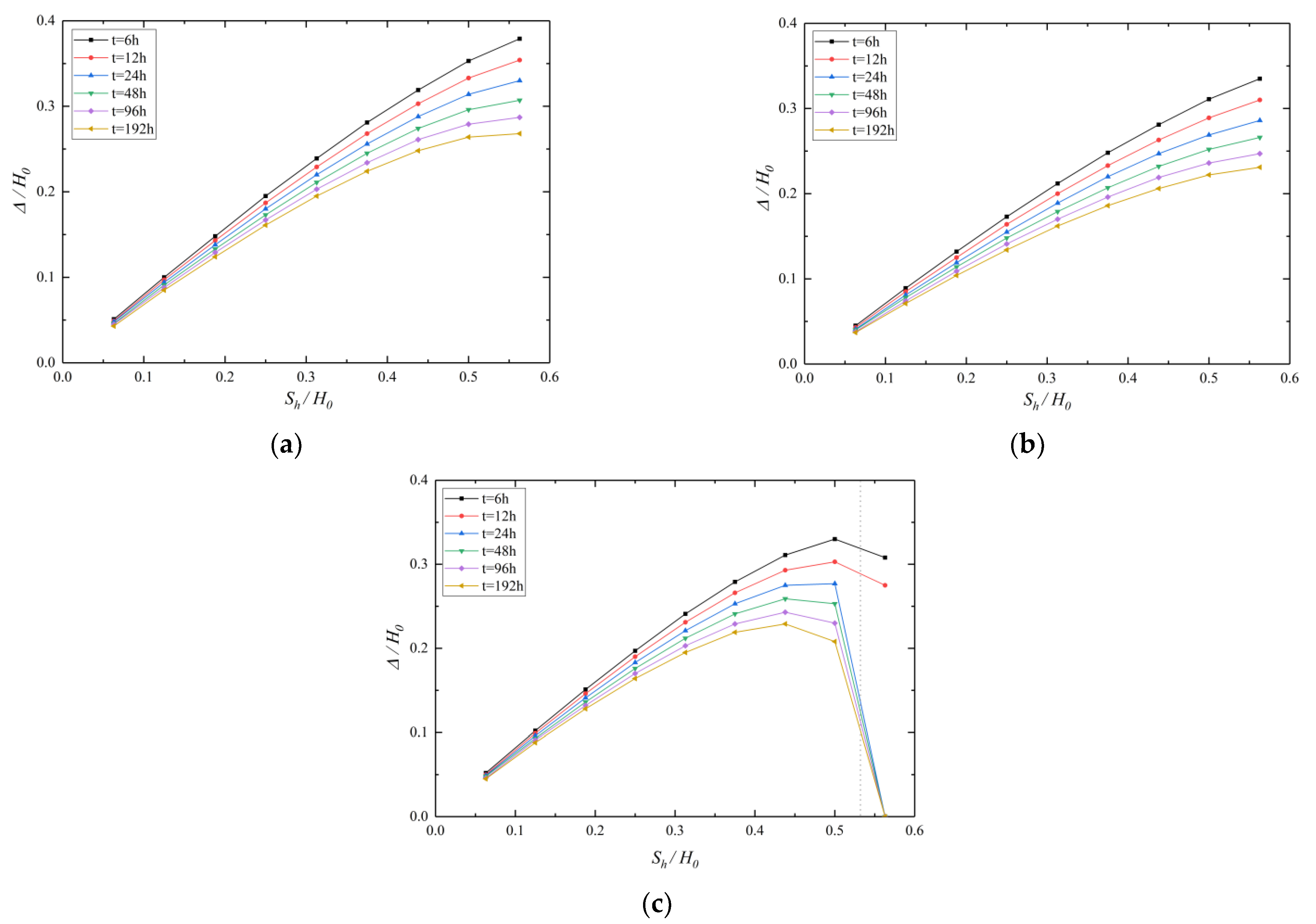
5.1. Effect of Sh
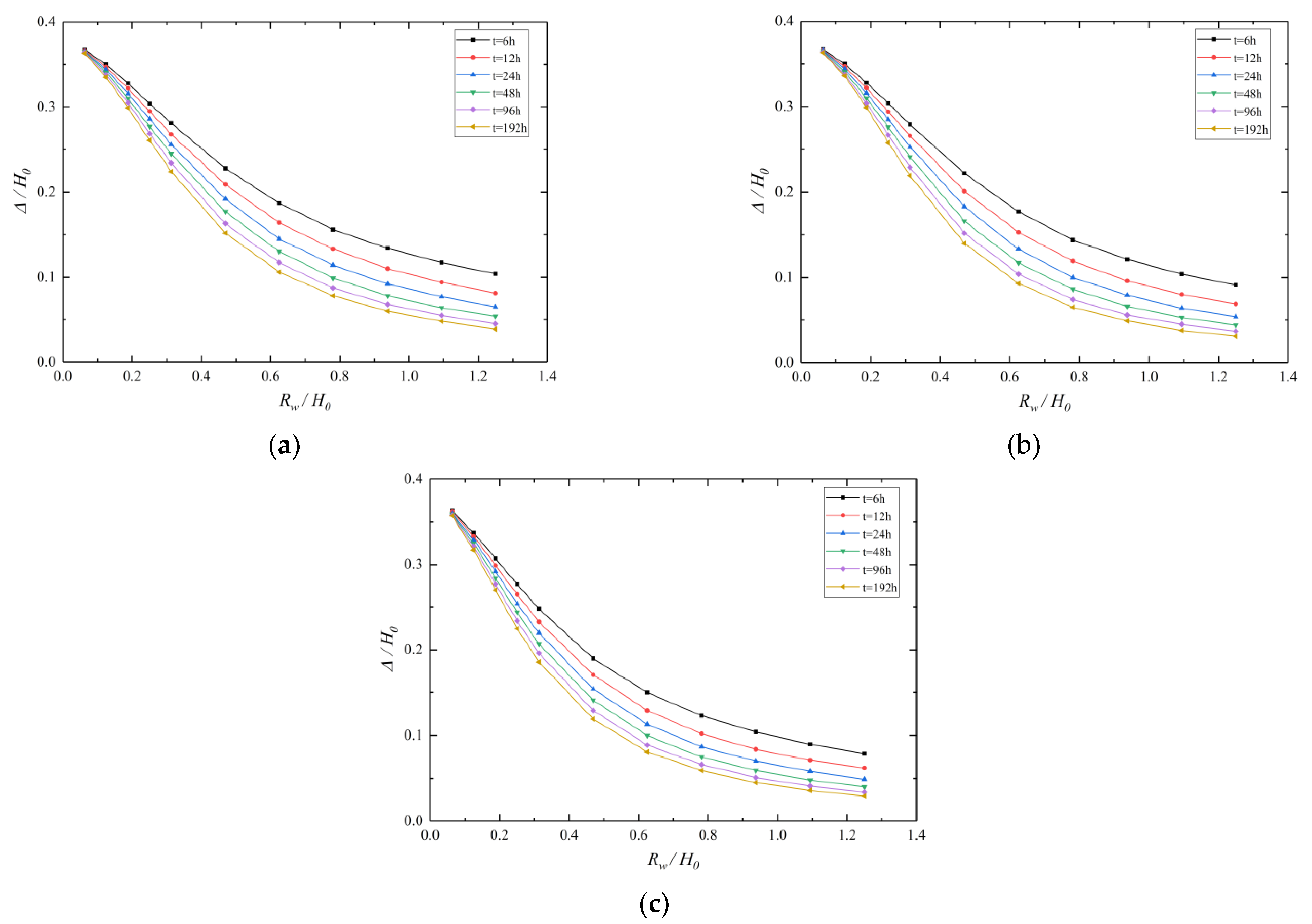
5.2. Effect of Rw
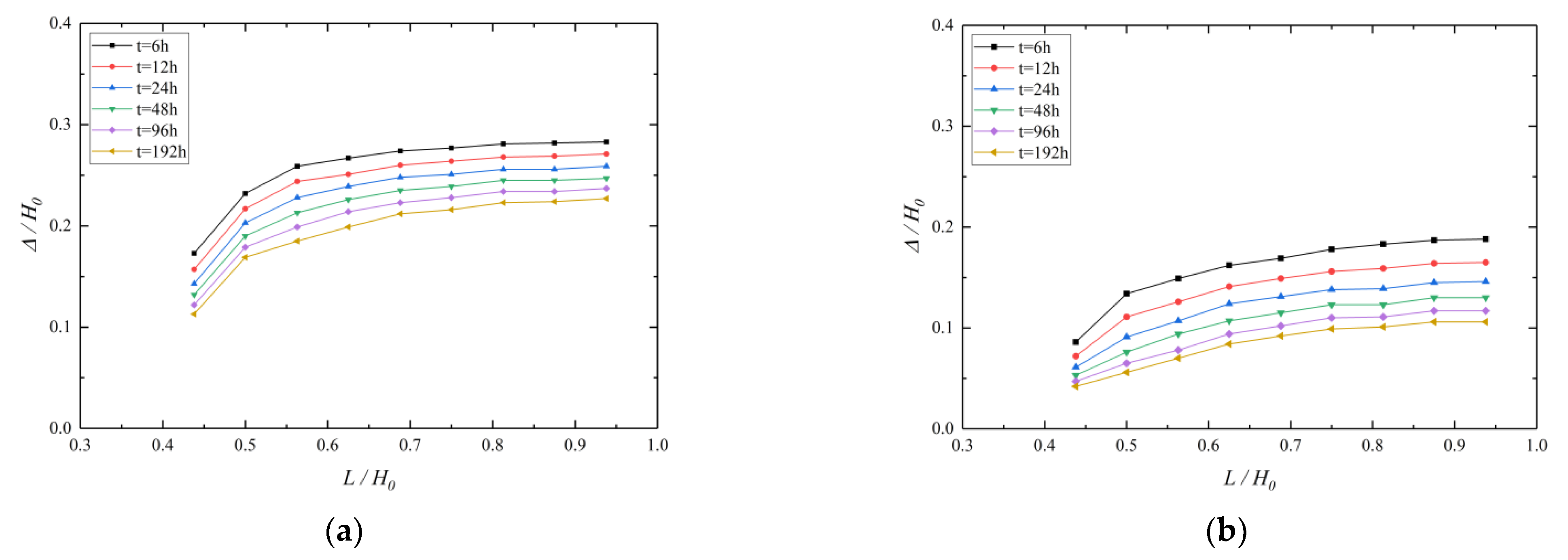
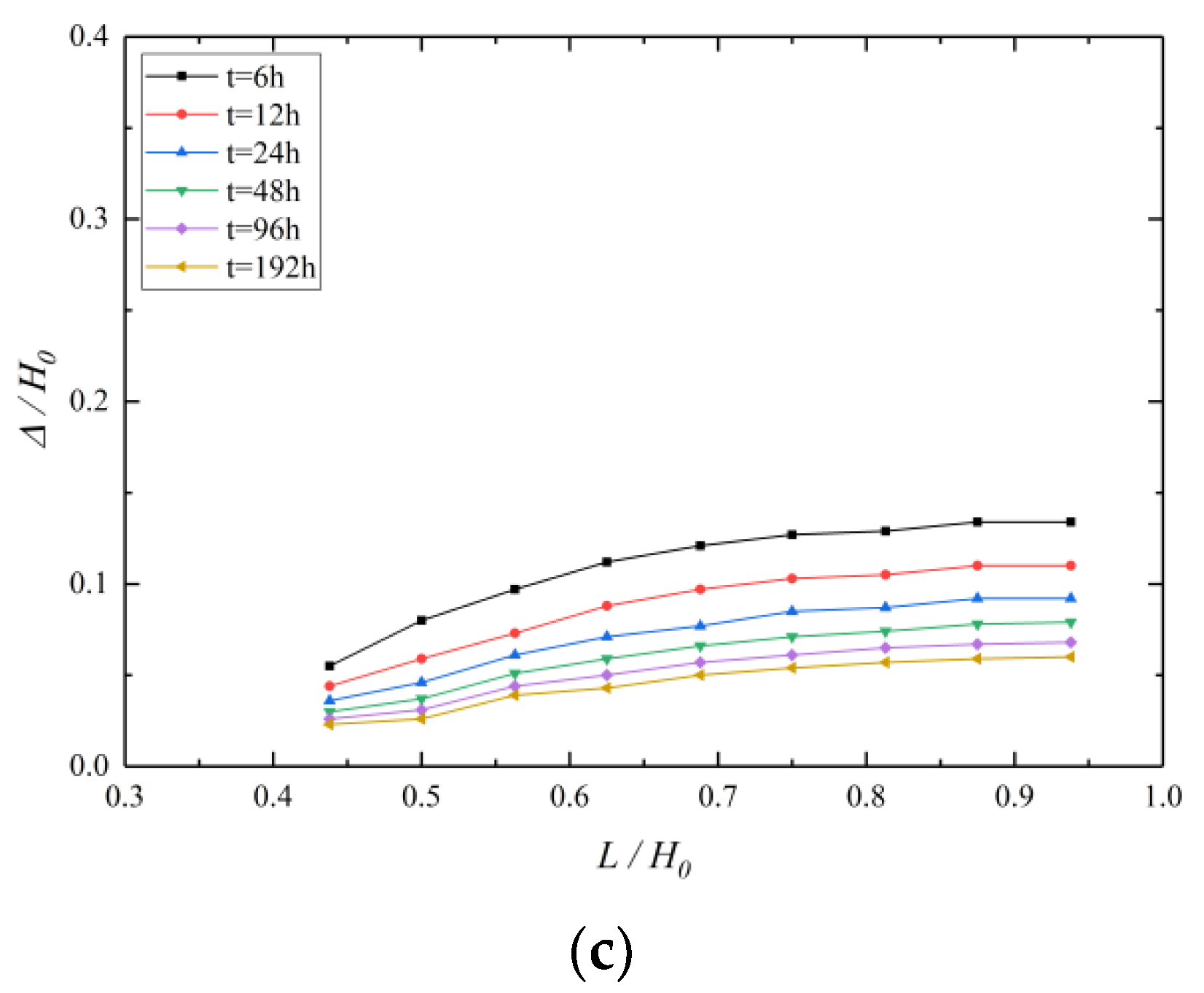
5.3. Effect of L
5.4. Effect of t
6. Conclusions
Author Contributions
Funding
Institutional Review Board Statement
Informed Consent Statement
Data Availability Statement
Conflicts of Interest
References
- Ng, C.; Hong, Y.; Liu, G.; Liu, T. Ground deformations and soil–structure interaction of a multi-propped excavation in Shanghai soft clays. Geotechnique 2012, 62, 907–921. [Google Scholar] [CrossRef]
- Li, M.G.; Zhang, Z.J.; Chen, J.; Wang, J.H.; Xu, A.J. Zoned and staged construction of an underground complex in Shanghai soft clay. Tunn. Undergr. Space Technol. 2017, 67, 187–200. [Google Scholar] [CrossRef]
- Wu, H.-N.; Shen, S.-L.; Yang, J. Identification of Tunnel Settlement Caused by Land Subsidence in Soft Deposit of Shanghai. J. Perform. Constr. Facil. 2017, 31, 4017092. [Google Scholar] [CrossRef] [Green Version]
- Wang, W.; He, X. Study on the Key Technology of Marshland Foundation Pit Construction. Geotech. Geol. Eng. 2019, 38, 31–45. [Google Scholar] [CrossRef]
- Li, M.-G.; Demeijer, O.; Chen, J.-J. Effectiveness of servo struts in controlling excavation-induced wall deflection and ground settlement. Acta Geotech. 2020, 15, 2575–2590. [Google Scholar] [CrossRef]
- Jiao, J.J.; Wang, X.S.; Nandy, S. Preliminary assessment of the impacts of deep foundations and land reclamation on groundwater flow in a coastal area in Hong Kong, China. Hydrogeol. J. 2004, 14, 100–114. [Google Scholar] [CrossRef]
- Zhou, N.; Vermeer, P.A.; Lou, R.; Tang, Y.; Jiang, S. Numerical simulation of deep foundation pit dewatering and optimization of controlling land subsidence. Eng. Geol. 2010, 114, 251–260. [Google Scholar] [CrossRef]
- Tan, Y.; Lu, Y.; Wang, D. Deep Excavation of the Gate of the Orient in Suzhou Stiff Clay: Composite Earth-Retaining Systems and Dewatering Plans. J. Geotech. Geoenviron. Eng. 2018, 144, 5017009. [Google Scholar] [CrossRef]
- Li, M.G.; Chen, J.J.; Xia, X.H.; Zhang, Y.Q.; Wang, D.F. Statistical and hydro-mechanical coupling analyses on groundwater drawdown and soil deformation caused by dewatering in a multi-aquifer-aquitard system. J. Hydrol. 2020, 589, 125365. [Google Scholar] [CrossRef]
- Xu, C.; Yang, K.; Fan, X.; Ge, J.; Jin, L. Numerical Investigation on Instability of Buildings Caused by Adjacent Deep Excavation. J. Perform. Constr. Facil. 2021, 35, 4021040. [Google Scholar] [CrossRef]
- Tan, Y.; Lu, Y. Responses of shallowly buried pipelines to adjacent deep excavations in Shanghai soft ground. J. Pipeline Syst. Eng. Pract. 2018, 9, 5018002. [Google Scholar] [CrossRef]
- Lu, C.; Huang, L. Study on the Effect of Foundation Pit Excavation on the Deformation of Adjacent Shield Tunnel. Adv. Civ. Eng. 2022, 2022, 8441758. [Google Scholar] [CrossRef]
- Sun, W.; Zhou, W.; Jiao, J. Hydrogeological Classification and Water Inrush Accidents in China’s Coal Mines. Mine Water Environ. 2015, 35, 214–220. [Google Scholar] [CrossRef]
- Tan, Y.; Lu, Y. Forensic Diagnosis of a Leaking Accident during Excavation. J. Perform. Constr. Facil. 2017, 31, 4017061. [Google Scholar] [CrossRef]
- Su, M.; Liu, Y.; Xue, Y.; Nie, L.; Wang, P.; Li, C.; Ma, X. Integrated geophysical detection of water inrush from foundation pit near the river: A case study of Nanjing subway station. Environ. Earth Sci. 2021, 80, 699. [Google Scholar] [CrossRef]
- Xu, X.B.; Hu, Q.; Huang, T.M.; Chen, Y.; Shen, W.M.; Hu, M.Y. Seepage failure of a foundation pit with confined aquifer layers and its reconstruction. Eng. Fail. Anal. 2022, 138, 106366. [Google Scholar] [CrossRef]
- Zeng, C.F.; Zheng, G.; Xue, X.L.; Mei, G.-X. Combined recharge: A method to prevent ground settlement induced by redevelopment of recharge wells. J. Hydrol. 2018, 568, 1–11. [Google Scholar] [CrossRef]
- Liu, N.W.; Peng, C.X.; Li, M.G.; Chen, J.J. Hydro-mechanical behavior of a deep excavation with dewatering and recharge in soft deposits. Eng. Geol. 2022, 307, 106780. [Google Scholar] [CrossRef]
- Zhang, X.Q.; Li, M.G.; Chen, J.J. Hydro-mechanical analysis of a braced foundation pit affected by rainfall and excavation in unsaturated soils. Acta Geotech. 2022, 1–16. [Google Scholar] [CrossRef]
- Peng, C.; Liu, N.; Li, M.; Zhen, L.; Chen, J. Hydro-mechanical coupled analyses on wall deformations caused by deep excavations and dewatering in a confined aquifer. Acta Geotechnica 2022, 17, 2465–2479. [Google Scholar] [CrossRef]
- Wu, Y.X.; Shen, S.L.; Yuan, D.J. Characteristics of dewatering induced drawdown curve under blocking effect of retaining wall in aquifer. J. Hydrol. 2016, 539, 554–566. [Google Scholar] [CrossRef]
- Wang, X.W.; Yang, T.L.; Xu, Y.S.; Shen, S.L. Evaluation of optimized depth of waterproof curtain to mitigate negative impacts during dewatering. J. Hydrol. 2019, 577, 123969. [Google Scholar] [CrossRef]
- Zhang, X.S.; Wang, J.X.; Wong, H.; Leo, C.J.; Liu, Q.; Tang, Y.Q.; Yan, X.L.; Sun, W.H.; Huang, Z.Q.; Hao, X.H. Land subsidence caused by internal soil erosion owing to pumping confined aquifer groundwater during the deep foundation construction in shanghai. Nat. Hazards 2013, 69, 473–489. [Google Scholar] [CrossRef]
- Wu, Y.X.; Shen, S.L.; Wu, H.N.; Xu, Y.S.; Yin, Z.; Sun, W.J. Environmental protection using dewatering technology in a deep confined aquifer beneath a shallow aquifer. Eng. Geol. 2015, 196, 59–70. [Google Scholar] [CrossRef]
- Tarshish, M. Modifications of Combined Mathematical Model of Flow in an Aquifer-Vertical Well System. Ground Water 1998, 36, 7–8. [Google Scholar] [CrossRef]
- Hu, L.; Chen, C. Analytical methods for transient flow to a well in a confined-unconfined aquifer. Ground Water 2008, 46, 642–646. [Google Scholar] [CrossRef]
- Anwar, S. A generalized model for pumping well hydraulics in confined aquifers. J. Hydroinformatics 2018, 20, 1085–1099. [Google Scholar] [CrossRef]
- Luther, K.; Haitjema, H. An analytic element solution to unconfined flow near partially penetrating wells. J. Hydrol. 1999, 226, 197–203. [Google Scholar] [CrossRef]
- Li, J.; Xia, X.H.; Li, M.G.; Chen, J.J.; Zhan, H. Nonlinear drainage model of viscoelastic aquitards considering non-Darcian flow. J. Hydrol. 2020, 587, 124988. [Google Scholar] [CrossRef]
- Jacob, C.E.; Lohman, S.W. Nonsteady flow to a well of constant drawdown in an extensive aquifer. Trans. Am. Geophys. Union 1952, 33, 559. [Google Scholar] [CrossRef]
- Pasandi, M.; Samani, N.; Barry, D. Effect of wellbore storage and finite thickness skin on flow to a partially penetrating well in a phreatic aquifer. Adv. Water Resour. 2008, 31, 383–398. [Google Scholar] [CrossRef]
- Xu, Y.; Shen, S.; Ren, D.; Wu, H. Analysis of factors in land subsidence in shanghai: A view based on a strategic environmental assessment. Sustainability 2016, 8, 573. [Google Scholar] [CrossRef] [Green Version]
- Shi, J.; Wu, B.; Liu, Y.; Xu, S.; Hou, J.; Wang, Y.; Sun, Q.; Meng, G.; Nong, Z.; Qiu, H.; et al. Analysis of the influence of groundwater seepage on the deformation of deep foundation pit with suspended impervious curtain. Adv. Mech. Eng. 2022, 14, 16878132221085128. [Google Scholar] [CrossRef]
- Zheng, G.; Dai, X.; Diao, Y.; Zeng, C.-F. Experimental and simplified model study of the development of ground settlement under hazards induced by loss of groundwater and sand. Nat. Hazards 2016, 82, 1869–1893. [Google Scholar] [CrossRef]
- Xu, Y.; Yan, X.; Shen, S.; Zhou, A. Experimental investigation on the blocking of groundwater seepage from a waterproof curtain during pumped dewatering in an excavation. Hydrogeol. J. 2019, 27, 2659–2672. [Google Scholar] [CrossRef]
- Wang, J.; Liu, X.; Liu, S.; Zhu, Y.; Pan, W.; Zhou, J. Physical model test of transparent soil on coupling effect of cut-off wall and pumping wells during foundation pit dewatering. Acta Geotech. 2019, 14, 141–162. [Google Scholar] [CrossRef]
- Luo, Z.; Zhang, Y.; Wu, Y. Finite element numerical simulation of three-dimensional seepage control for deep foundation pit dewatering. J. Hydrodyn. 2008, 20, 596–602. [Google Scholar] [CrossRef]
- Yuan, C.; Hu, Z.; Zhu, Z.; Yuan, Z.; Fan, Y.; Guan, H.; Li, L. Numerical Simulation of Seepage and Deformation in Excavation of a Deep Foundation Pit under Water-Rich Fractured Intrusive Rock. Geofluids 2021, 2021, 6628882. [Google Scholar] [CrossRef]
- Li, X.; Zhou, T.; Wang, Y.; Han, J.; Wang, Y.; Tong, F.; Li, D.; Wen, J. Response Analysis of Deep Foundation Excavation and Dewatering on Surface Settlements. Adv. Civ. Eng. 2020, 2020, 8855839. [Google Scholar] [CrossRef]
- Xie, Z.; Shen, S.; Arulrajah, A.; Horpibulsuk, S. Environmentally sustainable groundwater control during dewatering with barriers: A case study in shanghai. Undergr. Space 2021, 6, 12–23. [Google Scholar] [CrossRef]
- Zhang, X.; Wang, X.; Xu, Y. Influence of Filter Tube of Pumping Well on Groundwater Drawdown during Deep Foundation Pit Dewatering. Water 2021, 13, 3297. [Google Scholar] [CrossRef]
- Zeng, C.; Wang, S.; Xue, X.; Zheng, G.; Mei, G. Evolution of deep ground settlement subject to groundwater drawdown during dewatering in a multi-layered aquifer-aquitard system: Insights from numerical modelling. J. Hydrol. 2021, 603, 127078. [Google Scholar] [CrossRef]
- Vilarrasa, V.; Carrera, J.; Jurado, A.; Pujades, E.; Vázquez-Suné, E. A methodology for characterizing the hydraulic effectiveness of an annular low-permeability barrier. Eng. Geol. 2011, 120, 68–80. [Google Scholar] [CrossRef]
- Xu, Y.; Shen, S.; Ma, L.; Sun, W.; Yin, Z. Evaluation of the blocking effect of retaining walls on groundwater seepage in aquifers with different insertion depths. Eng. Geol. 2014, 183, 254–264. [Google Scholar] [CrossRef]
- Halek, V.; Svec, J. Groundwater Hydraulics; Elsevier Scientific Pub. Co.: Amsterdam, The Netherlands, 1979. [Google Scholar]
- Sato, K.; Iwasa, Y. Groundwater Hydraulics; Springer: Tokyo, Japan, 2000. [Google Scholar]
- Nishitani, T. Similarity transformation of the Boltzmann equation. Phys. Fluids A Fluid Dyn. 1991, 3, 349–355. [Google Scholar] [CrossRef]
- Chopard, B.; Pham, V.; Lefèvre, L. Asymmetric lattice Boltzmann model for shallow water flows. Comput. Fluids 2013, 88, 225–231. [Google Scholar] [CrossRef]
- DL/T 5213-2005; Code of Pumping Test in Borehole for Hydropower and Water Conservancy Engineering. Chinese Standard: Beijing, China, 2005. (In Chinese)


| Soil Stratum | Soil Number | Unit Weight γ (kN/m3) | Cohesion c (kPa) | Internal Friction Angle φ (°) | Modulus of Deformation E0 (MPa) | Permeability Coefficient K (m/d) |
|---|---|---|---|---|---|---|
| Fill | ① | 18.5 | 12 | 10 | 5.7 | 5 |
| Silt clay | ②-2 | 18.0 | 6 | 2 | 7 | 0.003 |
| Silty clay | ③-1 | 18.8 | 33 | 12 | 18 | 0.004 |
| Fine sand | ③-2 | 19.6 | 2 | 28 | 23 | 15 |
| Medium sand | ③-3 | 19.7 | 1 | 31 | 29 | 40 |
| Coarse sand | ③-4 | 19.8 | 1 | 34 | 32 | 80 |
| Gravelly sand | ③-5 | 20.0 | 1 | 36 | 33 | 100 |
| Rounded gravel | ③-6 | 20.5 | 1 | 38 | 35 | 120 |
| Weathered rock | ⑤-1–3 | 23.9 | 350 | 32 | 70 | 0.1 |
| Name | Value |
|---|---|
| Groundwater type | Phreatic aquifer |
| Radius of pumping well | 0.1 m |
| Length of pumping well | 9.5 m |
| Pumping time | 8 h |
| r1 | 5 m |
| r2 | 10 m |
| Test Stratum | Groundwater Drawdown Sw (m) | Water Inflow Q (m3/d) | Calculated Value K (m/d) |
|---|---|---|---|
| Coarse sand ③-4 Gravelly sand ③-5 | 1.21 | 176.8 | 52.4 |
| 2.65 | 360.3 | 62.1 | |
| 3.93 | 471.4 | 57.8 |
| γunsat (kN/m3) | c’kPa | φ’ (°) | Ψ (°) | E50ref (kN/m2) | Eoedref (kN/m2) |
| 18.0 | 7 | 30.7 | 0 | 25,000 | 25,000 |
| Eurref (kN/m2) | m | ν | Pref(kPa) | Rf | G0ref (kN/m2) |
| 75,000 | 0.7 | 0.2 | 100 | 0.9 | 150,000 |
| Names | Sh/H0 | Rw/H0 | L/H0 |
|---|---|---|---|
| Effect of Sh | (0.063–0.563) | 0.313 | 0.844 |
| 0.688 | |||
| 0.531 | |||
| Effect of Rw | 0.375 | (0.063–1.250) | 0.844 |
| 0.688 | |||
| 0.531 | |||
| Effect of L | 0.375 | 0.313 | (0.438–0.938) |
| 0.625 | |||
| 0.938 |
Publisher’s Note: MDPI stays neutral with regard to jurisdictional claims in published maps and institutional affiliations. |
© 2022 by the authors. Licensee MDPI, Basel, Switzerland. This article is an open access article distributed under the terms and conditions of the Creative Commons Attribution (CC BY) license (https://creativecommons.org/licenses/by/4.0/).
Share and Cite
Yang, K.; Xu, C.; Chi, M.; Wang, P. Analytical Analysis of the Groundwater Drawdown Difference Induced by Foundation Pit Dewatering with a Suspended Waterproof Curtain. Appl. Sci. 2022, 12, 10301. https://doi.org/10.3390/app122010301
Yang K, Xu C, Chi M, Wang P. Analytical Analysis of the Groundwater Drawdown Difference Induced by Foundation Pit Dewatering with a Suspended Waterproof Curtain. Applied Sciences. 2022; 12(20):10301. https://doi.org/10.3390/app122010301
Chicago/Turabian StyleYang, Kaifang, Changjie Xu, Minliang Chi, and Pei Wang. 2022. "Analytical Analysis of the Groundwater Drawdown Difference Induced by Foundation Pit Dewatering with a Suspended Waterproof Curtain" Applied Sciences 12, no. 20: 10301. https://doi.org/10.3390/app122010301