Article

Research on Grinding Force of Ultrasonic Vibration-Assisted Grinding of C/SiC Composite Materials

1
School of Mechanical Engineering and Automation, Beihang University, Beijing 100191, China
2
School of Automation Science and Electrical Engineering, Beihang University, Beijing 100191, China
3
Beijing Institute of Electronic System Engineering, Beijing 100854, China
*
Author to whom correspondence should be addressed.
Appl. Sci. 2022, 12(20), 10352; https://doi.org/10.3390/app122010352
Submission received: 18 September 2022 / Revised: 8 October 2022 / Accepted: 10 October 2022 / Published: 14 October 2022
(This article belongs to the Section Mechanical Engineering)

Abstract

:
C/SiC composite material is the best choice for important parts such as the hot-end structure of aerospace vehicles. Research and optimization of the cutting force of ultrasonic vibration-assisted grinding are of great significance when it comes to revealing the machining mechanism of C/SiC composites and realizing low-damage and efficient machining. In this paper, the comparative experimental study of ultrasonic vibration-assisted grinding and common grinding of C/SiC composites is carried out; the variation laws of grinding force and grinding force ratio with different machining methods and process parameters are analyzed, and the empirical formulas of ultrasonic-assisted grinding are summarized. The research results show that ultrasonic vibration can soften C/SiC materials and sharpen the cutting to a certain extent through the action of high-frequency impact, greatly reduce the value of the grinding force, and improve the machinability of the material. Thus, ultrasonic-vibration-assisted grinding processing is an effective method to achieve high-efficiency and low-damage processing of C/SiC composites.

1. Introduction

Fiber-reinforced silicon carbide matrix composite (C/SiC) is a thermal structure composite material that appeared in the 1980s. It takes silicon carbide as the matrix and carbon fiber for reinforcement. It effectively combines the superior physical properties of carbon fiber with good chemical and thermal stability of the ceramic matrix [1,2]. Compared with high-temperature metal materials, it can increase the working temperature by 300 C 500 C , reduce the weight of the structure by 50∼70%, and increase the thrust by 30∼ 100 % [3]. Compared with C/C composite materials, in addition to its excellent properties such as high specific strength, high specific modulus, and excellent high-temperature mechanical properties, it also has more prominent properties such as high densification, long service life, and strong environmental adaptability. In particular, its high resistance to oxidation lends it excellent high-temperature mechanical properties [4,5]. The United States, Japan, France, Germany, and other countries have gradually applied C/SiC composite materials in the hot end parts of high thrust-to-weight ratio aero-engines, aerial brake pads, and other wear-resistant materials [3].
Because the forming surface of the C/SiC composite material component is very rough, and the dimensional accuracy is extremely low, it must go through a cutting process before assembly. However, C/SiC composite material is a typical of high-temperature structural composite material with a small amount of research basis. This material has high hardness, poor thermal conductivity and anisotropy characteristics of composite materials. Therefore, in the process of material cutting, there are a series of problems, such as large cutting force, serious surface damage, serious tool wear, and low service life, which seriously affect the production efficiency and service performance of composite components [1,6]. Therefore, how to reduce the processing damage of C/SiC composites, improve the processing efficiency, and ensure the processing accuracy has become a bottleneck problem in engineering applications that urgently needs to be resolved. Grinding is a suitable method for processing high-hardness and high-brittleness materials. The grinding wheel with high machining accuracy, small surface roughness, and self-sharpening has a strong removal effect on high-hardness and high-brittleness materials, so it is used in processing materials similar to C/SiC composite materials.
In recent years, the ultrasonic-vibration-assisted grinding (UVAG) method has been used increasingly often to process high-hardness and high-brittleness materials such as ceramics and ceramic matrix composites. Scholars have conducted many theoretical and experimental studies on grinding wheel wear [7,8], abrasive particle motion trajectory [8,9,10], and processing damage formation mechanism of ultrasonic vibration-assisted grinding [11,12]. The results show that ultrasonic vibration is conducive to reduce cutting force and tool wear [13,14], and the processing efficiency is improved to 6∼10 times that of common grinding [15].
At the same time, some scholars have carried out modeling, simulation, experiments, and other related research on the cutting force of ultrasonic-vibration-assisted grinding. Firstly, some scholars analyzed the kinematics of ultrasonic-vibration-assisted grinding, and summarized the kinematics principle that ultrasonic-vibration-assisted cutting can help to improve machining accuracy and surface quality. Peng et al. studied the kinematic characteristics of a two-dimensional vertical ultrasonic-vibration-assisted grinding method [10]. They established a consistent physical model of the ultrasonic-vibration-assisted grinding process based on a kinematics equations to study the interaction between a single abrasive particle and the workpieces. A simulation proved that with the assistance of ultrasonic vibration, the grinding path of the particle becomes longer. The material removal rate of each particle has been improved. In addition to modeling and simulation analysis, they also conducted an ultrasonic-assisted grinding experiment using polysilicon, which proved that the assistance of ultrasonic vibration could indeed change the grinding mechanism of brittle materials. In addition, Zhang et al. proposed an ultrasonic-assisted micro end grinding (UAMEG) processing method [9]. They also modeled and simulated the trajectories of two adjacent abrasives, analyzed their kinematics mechanism, and obtained the mathematical critical conditions for the separation of high-frequency abrasive workpieces. The effect of frequency coefficients was studied via the kinematics. From the kinematics perspective, it is proved that the UAMEG can reduce the cutting force and temperature, smooth chip removal, extend the tool life, and improve the machining accuracy. It provides model guidance and theoretical support for the actual ultrasonic-vibration-assisted grinding process.
Secondly, some scholars have studied the ultrasonic-vibration-assisted grinding force model. Hecker et al. proposed a prediction model of grinding force and power based on undeformed chip thickness probability distribution in grinding wheel grinding [16]. They calculated the dynamic cutting edge density based on kinematics and dynamics. The elastic deformation of the grinding contact length was also considered. Through the chip thickness probability distribution, the normal force and tangential force and power of orthogonal test for the total tangential plane grinding force, and normal force and external circular grinding test were carried out to verify the total grinding power prediction model. It is concluded that the model can effectively predict the grinding wheel grinding chip thickness without deformation of the probability distribution of the conclusion of grinding force and power. Xiao et al. conducted experiments on the ultrasonic-vibration-assisted grinding technology of dental zirconia ceramics using the single-factor method [17]. They proposed an exponential prediction model, a BP neural network prediction model, and a theoretical prediction model of the UVAG cutting force. The experiments have verified the prediction accuracy of these three models and revealed the cause of the error. The results show that the BP neural network prediction model has higher accuracy than the other two, and the relative error is only 9.60 % . In order to reveal the mechanism of reducing grinding force and improving grinding surface quality in the UVAG process, Wang et al. took “brittle fracture as the main mechanism of material removal in the UVAG process of brittle materials” as the starting point, and gradually established the mathematical model of system matching in the UVAG process of brittle materials [18]. The mechanism of surface roughness formation in processing brittle materials by UVAG method and how UVAG helps to reduce grinding force were also discussed. The advantages of UVAG method for brittle materials are pointed out theoretically. The model is also used to predict the impact of input variables on the grinding force, which can provide convenience in developing the brittle material grinding force model in the UVAG process and a useful basis for predicting the surface roughness after using the UVAG method.
From the above literature review, although there are some research studies on the grinding force of ultrasonic-vibration-assisted grinding, the characteristics of materials have an important influence on the effect of ultrasonic-vibration-assisted machining, especially with regard to the composites with more complex components and structures. In particular, there are few reports on the grinding force research on ultrasonic-vibration-assisted grinding of C/SiC composite materials.
In this paper, an ultrasonic-vibration-assisted grinding force of C/SiC composite materials is experimentally studied. A sintered diamond grinding head is used to process C/SiC composite materials using common grinding and ultrasonic vibration-assisted grinding on the same equipment. The grinding force in the machining process is measured, and the variation law of grinding force is analyzed and summarized to grasp the force characteristics and influencing factors in ultrasonic-vibration-assisted grinding of C/SiC composite materials.

2. Experimental Plan

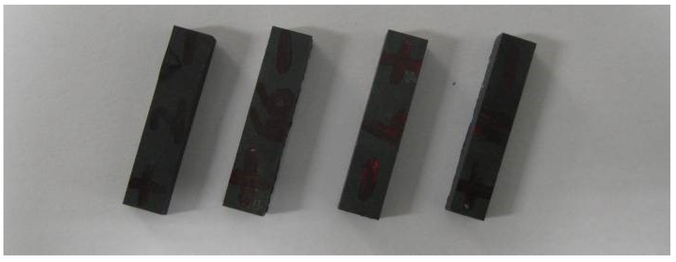
2.1. Materials Used for Testing

The structural characteristics of the C/SiC composite material used in the cutting experiment in this paper are as follows. The fiber used was T700 carbon fiber. The single-layer 0 without-weft carbon fiber cloth, silicon carbide matrix layer, 90 without-weft carbon fiber cloth, and silicon carbide matrix layer were stacked in turn. The carbon fiber layer was unidirectional, and the silicon carbide matrix layer had short fibers distributed in the layer due to the existence of the mesh. The relay acupuncture technique was used to vertically pierce the short fibers in the mesh layer into the without-weft cloth to connect them as a whole. In the C/SiC composites, the volume fraction of carbon fiber was about 40 % , and the fiber bundle width along the same braided direction was about 250 μ m . As the weftless cloth used short carbon fiber as the needle punching material, the use amount was small, and the impact on the grinding process can be ignored.
During the test, the STX-202 diamond wire cutting machine (KEJING, Shenyang, China) was used to divide the whole material (as shown in Figure 1) into 36 specimens with a size of 35 mm long, 8 mm wide, 5 mm thick, as is shown in Figure 2. Among them, 12 were used for side grinding (two of them are spare), and 24 were used for end grinding (four of them are spare).

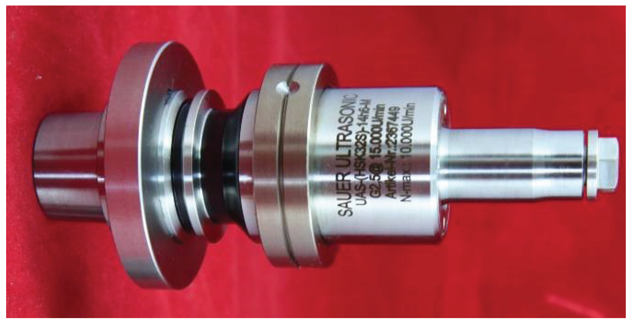
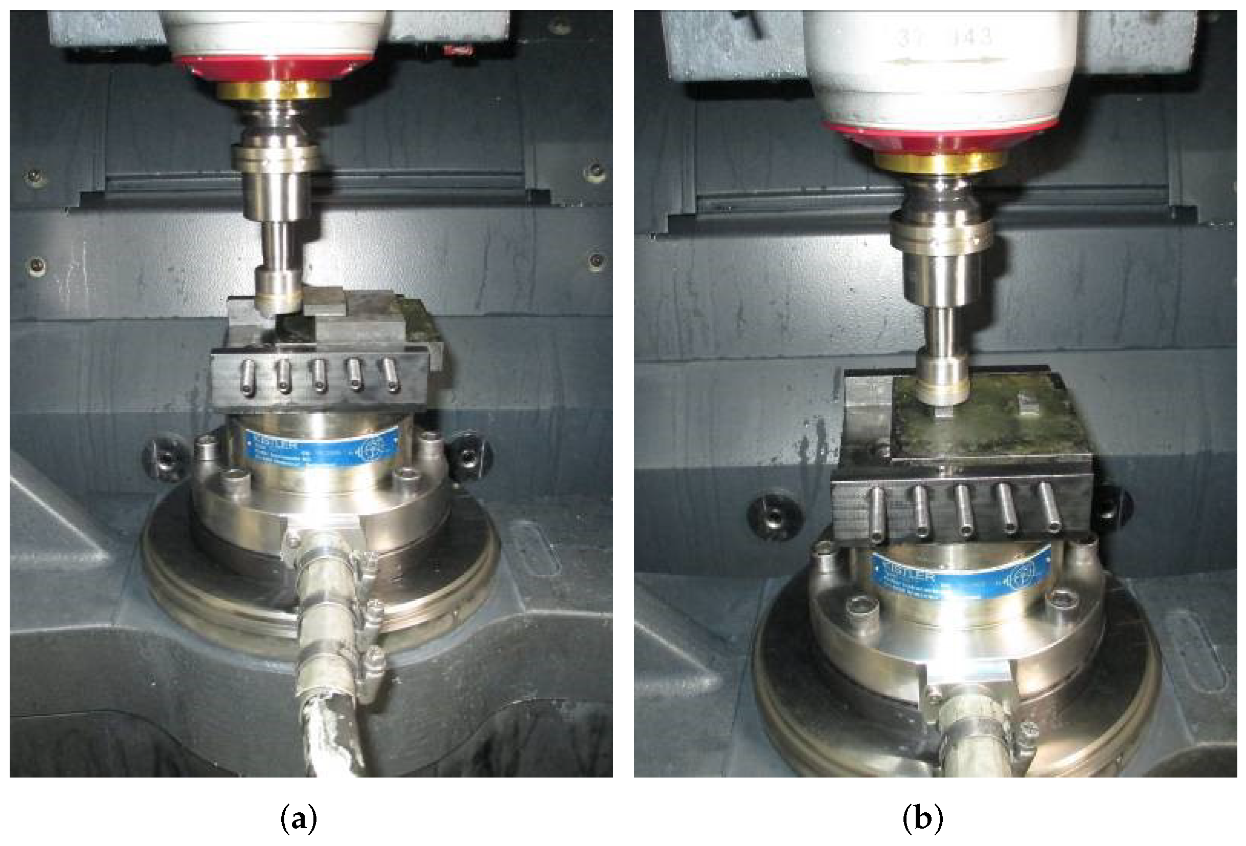
2.2. Test Devices and Process Parameters

The test was performed on a high-speed machining center (DMG Ultrasonic 20 Linear DMG MORI, Bielefeld, North Rhine-Westphalia, Germany). Both the common grinding test and the UVAG test were carried out with a 14h6 ultrasonic tool holder, as is shown in Figure 3. The tool used was a Schott cup-shaped sintered diamond grinding wheel, hollow structure, a total length of 60 mm , an outside diameter of 24 mm , and wall thickness of 2 mm . The average diamond abrasive particle size was about 300 μ m , and the edge height was about 100 μ m . Under the same grinding process conditions, the larger the diamond abrasive particle size, the smaller the grinding wheel mesh number. A larger abrasive particle size means larger chip space, which is helpful for material removal. The smaller the abrasive particle size, the smaller the top cone angle of the diamond abrasive particle, and the sharper it is. Under the same conditions, the contact area was smaller, and the grinding force was smaller. In order to study the influence of ultrasonic vibration on the grinding force, the grinding wheel with larger grain size and coarser was selected in this paper to fully study the influence of ultrasonic vibration on C/SiC grinding under small cutting data.
During the test, we replaced or modified the grinding wheel once for each single factor test. The coolant used was a water-based emulsion (Castrol, Berkshire, England) with a concentration of about 4∼5%. During the test, both internal and external cooling were turned on, the internal cooling pressure was 20 bar, and the external cooling pressure was 4 bar. The specific test device conditions are shown in Table 1.
The specific grinding process parameters for side grinding and end grinding are shown in Table 2 and Table 3, respectively. The grinding width b = 5 mm during side grinding (6 samples for the test), and the grinding width b = 8 mm during end grinding (12 samples for the test). The ultrasonic vibration amplitude was set as 6 μ m , and the main consideration was that the vibration amplitude should be less than the grinding depth so that the machining process was always maintained in the continuous vibration grinding state. In the continuous vibration range, the larger the vibration amplitude, the more prominent the effect of ultrasonic-assisted vibration on the grinding force.
The test scheme is determined separately to obtain the empirical formula of grinding force for common grinding and UVAG. The process parameters of side grinding and end grinding are shown in Table 4 and Table 5. The rest of the test conditions are the same as the previous test scheme, including four samples for side grinding and eight samples for face grinding. The grinding position of the sample is shown in Figure 4.

2.3. Observation Method

The KISTLER9272 three-way piezoelectric crystal dynamometer (Kistler Group, Eulachstrasse 22, 8408 Winterhur, Switzerland) was used to measure the grinding force. The grinding force measurement systems for side grinding and end grinding are shown in Figure 4. The Dynoware software is used to analyze and process the grinding force signal.

3. Result and Discussion

3.1. Typical Cutting Force Curve

In order to obtain the typical grinding force signals during common grinding (CG, without ultrasonic assistance) and UVAG of C/SiC composites, separate tests used relatively stable signal parameters. The test results are shown in Figure 5.
Figure 5 measures the normal force F n and tangential force F t of C/SiC processed by common grinding and UVAG. Figure 5a indicates that when common grinding and UVAG are used to process the side of the C/SiC test piece, the grinding force gradually increases from zero to a relatively stable platform value, which is caused by the gradual increase in the contact area when the grinding head cuts in. After entering stable grinding, the cutting force fluctuates in a certain range, and there are low valleys locally in some parts, which should be related to the material properties. Because C/SiC is wrapped by the SiC matrix on each layer of carbon fiber, the distribution will not be very uniform, and there will be a certain amount of pores. When grinding to a local position with high SiC content, the grinding force will increase, and vice versa. Therefore, the grinding force will show a peak-to-valley state change. In the early stage of grinding, the local low valley value should be caused by the sudden drop of local hardness caused by the local SiC porosity.
Meanwhile, Figure 5b shows that when common grinding and UVAG are used to process the end of the C/SiC test piece, the grinding force gradually increases from zero to a relatively stable platform value, which is caused by the gradual increase in the contact area when the grinding head cuts in. The amplitude of common grinding fluctuations is greater than that of UVAG. This is because the ultrasonic vibration buffers part of the grinding force changes and reduces the fluctuation range of the axial grinding force. However, the abrupt peaks that appeared in the middle and late stages existed in common grinding and ultrasonic grinding, which should be related to the material distribution.

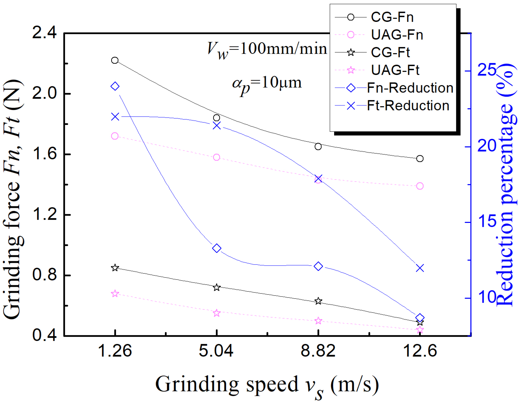
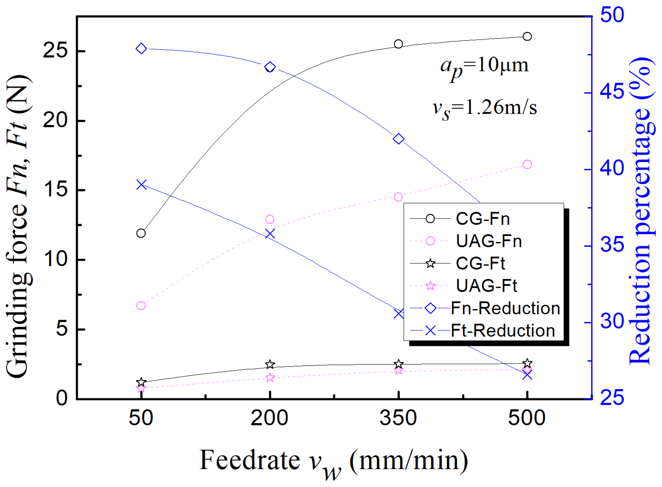
3.2. Influence of Main Processing Parameters

When using common grinding and UVAG to process the side of C/SiC composite material, the influence of the process parameters on the grinding force in the two states is shown in Figure 6, Figure 7 and Figure 8, respectively. Under all test conditions, UVAG can significantly reduce the grinding force. The maximum reduction range of normal grinding force and tangential grinding force is about 25 % .
Figure 6 shows the influence of grinding speed changes on the grinding force. With the increase in grinding speed, the grinding force of common grinding and UVAG has a downward trend. In addition, the amplitude of reducing cutting force by UVAG is lower than that of common grinding. This indicates that with the increase in the grinding speed, the ultrasonic assisting effect on the machining process tends to weaken. Figure 7 shows the influence law of grinding depth changes on the grinding force. With the increase in the grinding depth, the cutting force of common grinding and UVAG shows a significant increasing trend. Unlike the characteristics of the grinding speed, the increase in the grinding depth has a relatively small effect on the reduction in the grinding force. Figure 8 shows the law of the influence of the grinding feed speed on the grinding force. With the increase in the grinding feed speed, the grinding force of common grinding and UVAG has an increasing trend. Similarly, the feed speed changes within the range of the parameters have less influence on the ultrasonic assisting effect than the grinding speed.
Figure 9, Figure 10 and Figure 11, respectively, show the influence of grinding speed, grinding depth, and feed speed on the grinding force during end grinding. Compared with common grinding, UVAG can significantly reduce the grinding force during end grinding of C/SiC composites. The maximum reduction in normal grinding force is about 53 % , and the maximum reduction in tangential grinding force is about 40 % . As with side grinding, the increase in grinding speed can significantly reduce the amplitude of the grinding force. In addition, changes in feed speed and grinding depth also have a certain influence on grinding force, but the degree of influence is relatively small.

3.3. Comparative Analysis of Grinding Force Ratio

The grinding force ratio F n / F t is a typical parameter for evaluating the grindability of materials. The high ratio indicates that the material is crushed and removed under the action of normal force. The low ratio indicates that the material is removed by forming plastic chips under tangential force. This is an important reference for discriminating brittle-plastic removal of materials [19]. According to Figure 7 and Figure 10, at different grinding depths, the ratio of the grinding force increases with the increase in grinding depth. The normal force plays the main role, and its effect is deepening.
Figure 12 show the comparison of the grinding force ratio between common grinding and UVAG during side grinding and end grinding of C/SiC composites. Figure 12a shows that although UVAG can reduce the grinding force in the side grinding, the grinding force ratio is no different from that of common grinding. However, Figure 12b demonstrates that the grinding force ratio of UVAG during the end grinding is significantly lower than that of common grinding. The results show that in the process of end grinding, the grinding wheel is more likely to remove the brittle composite material C/SiC via plastic shear. It can theoretically obtain a smoother surface and make the grinding wheel appear more “sharp”, which is an important effect after the superposition of ultrasonic vibration.

3.4. Refinement of Grinding Force Empirical Formula

According to traditional cutting theory, there is a complex exponential relationship between grinding force and grinding process parameters. The classic grinding force formula is (1).
F t = F p a p x v s y v w z
where F p is a coefficient that combines the material to be processed and the grinding conditions. The exponential model of Equation (1) is nonlinear. In order to facilitate regression analysis, linearization is carried out first. After the regression, the regression equation can be obtained as (2):
y = b 0 + b 1 x + b 2 y + b 3 z
Encode the grinding amount level; the large value is + 1 , and the small value is 1 . The grinding force test values of common grinding and UVAG in the side grinding and end grinding tests are all taken as natural logarithms. The results are shown in Table 6, Table 7, Table 8 and Table 9, respectively.
From the test data in Table 6, the four coefficient values of b 0 , b 1 , b 2 , and b 3 in Equation (2) can be obtained through uniformity design software: b 0 = 1.36186 , b 1 = 0.62 , b 2 = 0.3 , b 3 = 0.11 . Then, we find the variable values in Equation (2): x = 0.62 , y = 0.3 , z = 0.11 , F p = 10 1.36186 = 23.01 . Finally, the empirical formula of grinding force for common grinding during side grinding is (3).
F t = 23.01 a p 0.62 v s 0.3 v w 0.11
In the same way, according to the test data in Table 7, Table 8 and Table 9, the UVAG force during side grinding, the common grinding force during end grinding, and the UVAG force during end grinding can be obtained in turn. The empirical formulas are (4)–(6).
F t = 21.48 a p 0.64 v s 0.27 v w 0.13
F t = 58.75 a p 0.69 v s 0.39 v w 0.12
F t = 42.95 a p 0.71 v s 0.27 v w 0.15

4. Conclusions

In this paper, the comparative experimental studies of common grinding and ultrasonic vibration-assisted grinding of C/SiC composites are carried out, and the changes in grinding force and grinding force ratio with different processing methods and processes parameters are analyzed. The main conclusions are as follows:
  • C/SiC composite material has the characteristics of uneven distribution of the matrix materials. The change in material hardness at different positions very easily leads to damage of the tool in the machining test, which will cause unpredictable adverse effects on the subsequent processing. Using UVAG can effectively weaken the influence of such uneven features on the machining and reduce the grinding force’s fluctuation range. This trend is more prominent in the end grinding.
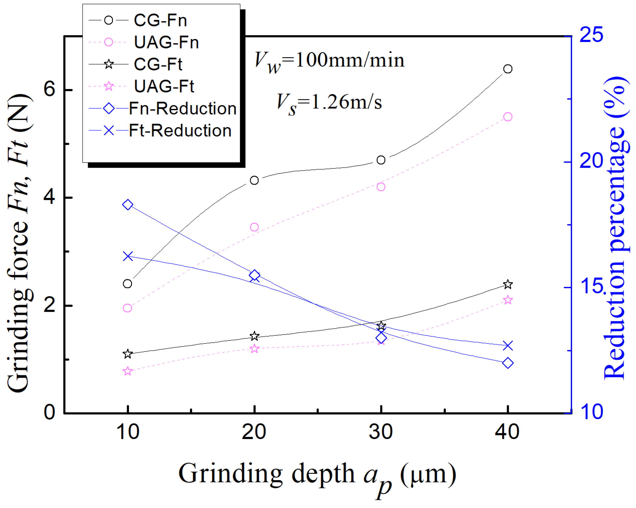
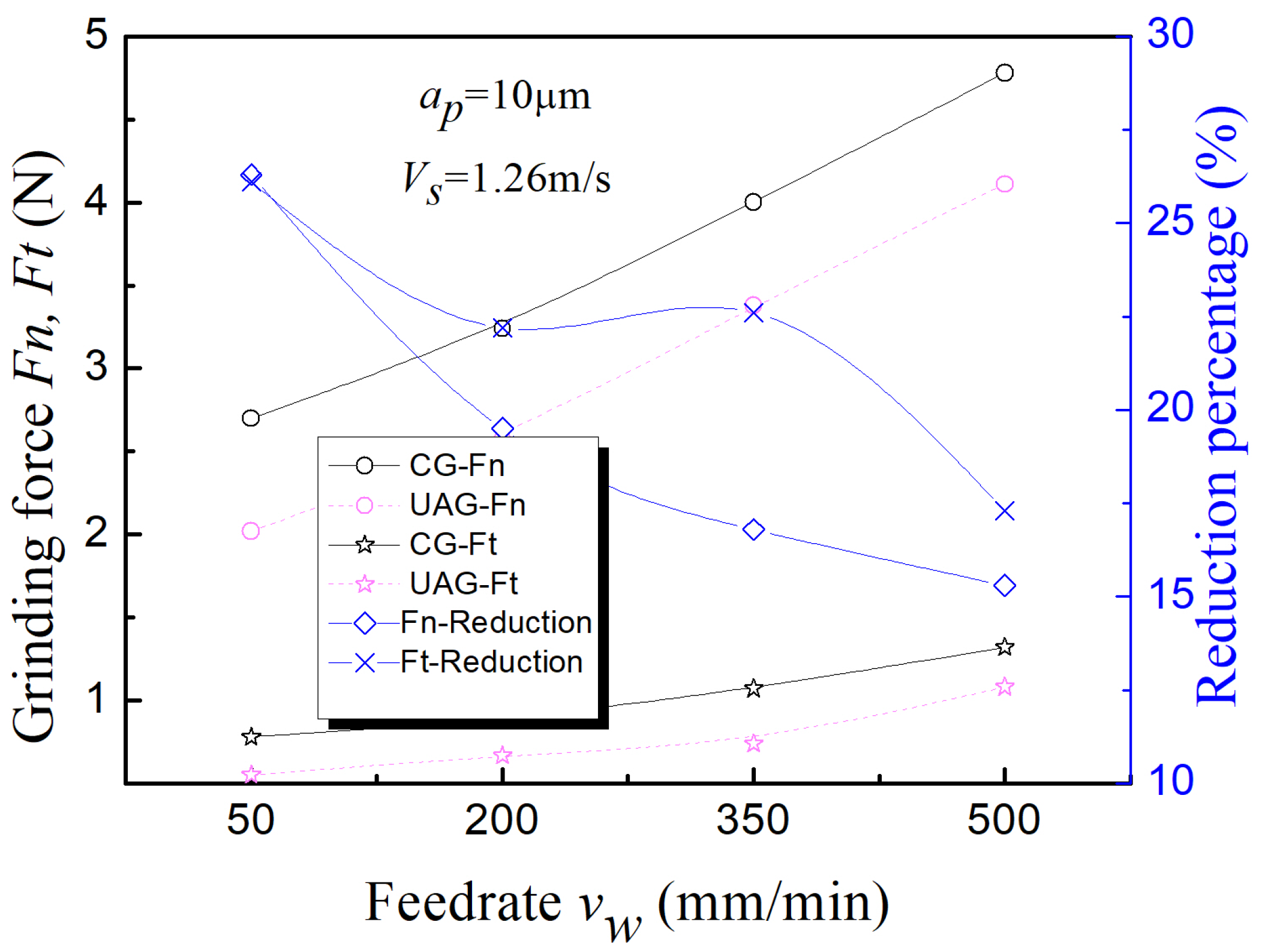
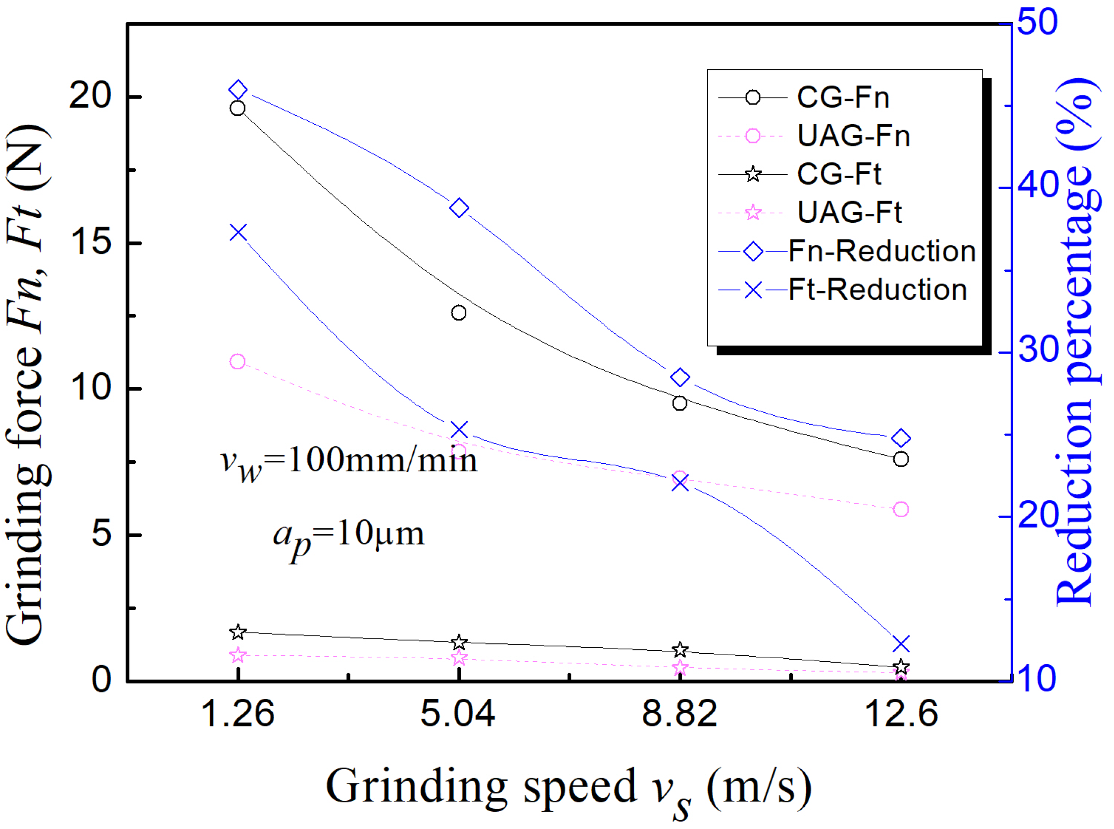
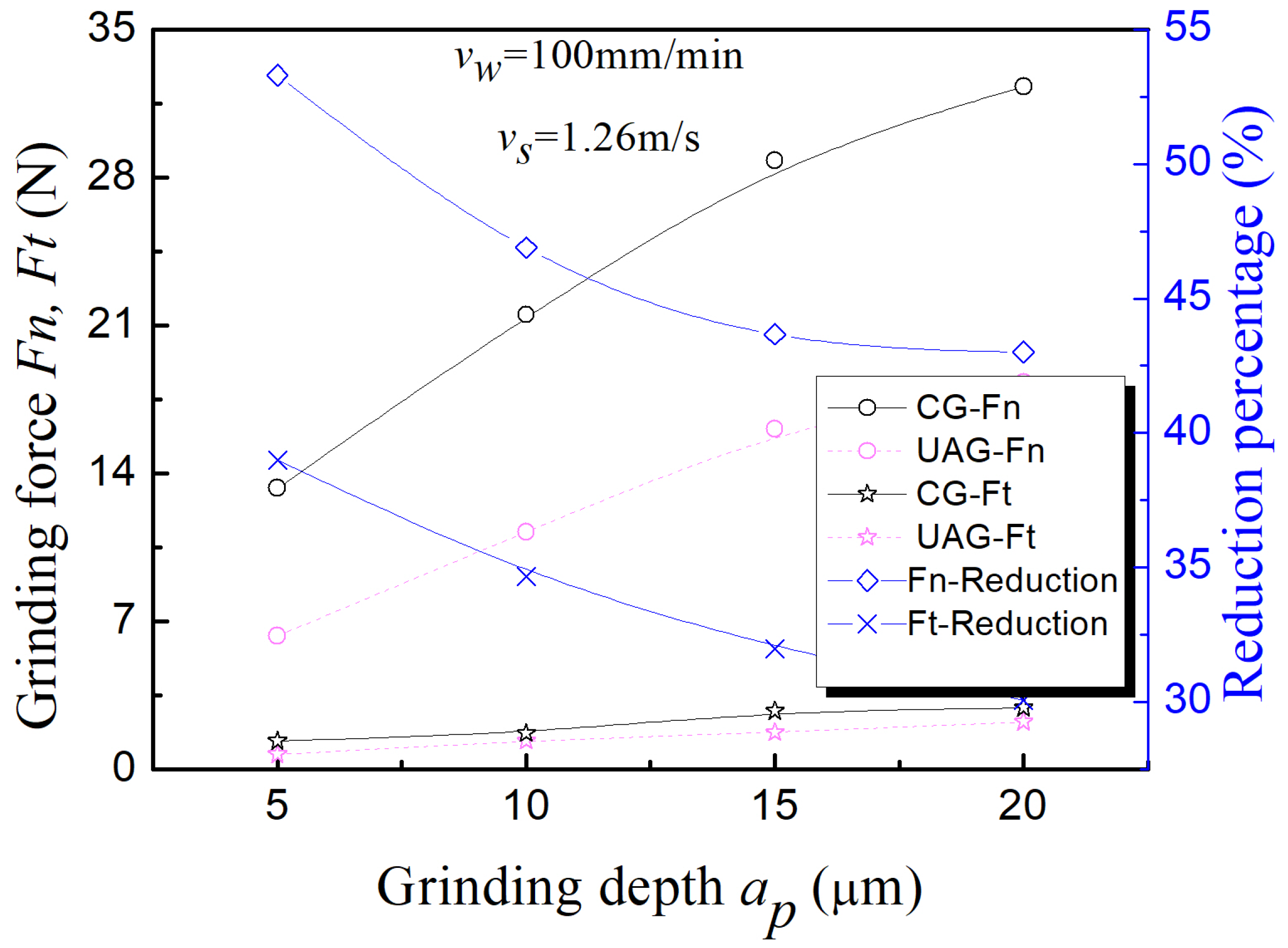
  • In the common and ultrasonic-assisted side grinding of C/SiC composites, the grinding speed, grinding depth, and feed speed have similar effects on the grinding force. Still, UVAG can significantly reduce the grinding force. The maximum reduction range of normal grinding force and tangential grinding force is about 25 % .
  • UVAG of C/SiC composite material can significantly reduce the grinding force compared with common grinding. The maximum reduction in normal grinding force is about 53 % , and the maximum reduction of tangential grinding force is about 40 % .
  • By comparing the grinding force ratio of side grinding and end grinding of C/SiC composite materials, it can be seen that during the side grinding, although UVAG can reduce the grinding force, the grinding force ratio is no different from that of common grinding. The grinding force ratio of UVAG during end grinding is significantly lower than that of common grinding, indicating that ultrasonic vibration can soften materials and sharpen cutting to a certain extent through high-frequency impact during end grinding, which greatly improves the machinability of materials.

Author Contributions

Conceptualization, D.W.; writing—original draft preparation, D.W.; writing—review and editing, D.W., H.F., D.X. and Y.Z.; supervision and project administration, D.X. All authors have read and agreed to the published version of the manuscript.

Funding

This research was funded by the National Natural Science Foundation of China grant number (No. 62073017).

Institutional Review Board Statement

Not applicable.

Informed Consent Statement

Not applicable.

Data Availability Statement

Not applicable.

Conflicts of Interest

The authors declare no conflict of interest.

References

  1. Krenkel, W.; Henke, T.; Mason, N. In-situ joined CMC components. In Key Engineering Materials; Trans Tech Publ: Zurich, Switzerland, 1997; Volume 127, pp. 313–320. [Google Scholar]
  2. Liu, W.; Wei, Y.; Deng, J. Carbon-fiber-reinforced C-SiC binary matrix composites. Carbon 1995, 33, 441–447. [Google Scholar] [CrossRef]
  3. Liu, Q.; Huang, S.; Aijie, H. Application requirements and challenges of CMC-SiC composites on aero-engine. J. Mater. Eng. 2019, 47, 1–10. [Google Scholar]
  4. Chen, D.; Han, W.; Li, S.; Lu, Z.; Qiu, H.; Shao, C.; Wang, C.; Wang, H.; Zhang, M.; Zhou, X.; et al. Fabrication, Microstructure, Properties and Applications of Continunous Ceramic Fibers: A Review of Present Status and Further Directions. Adv. Ceram. 2018, 3, 151–222. [Google Scholar]
  5. Zhao, D.; Yin, H.; Luo, F.; Zhou, W. Microstructure and Mechanical Property of 3D Textile C/SiC Composites Fabricated by Chemical Vapor Infiltration. In Advanced Materials Research; Trans Tech Publ: Zurich, Switzerland, 2006; Volume 11, pp. 81–84. [Google Scholar]
  6. Deng, J.; Liu, W.; Wei, Y.; Wang, Z. Preparation of carbon fiber reinforced carbon-silicon carbide gradient matrix composites by chemical vapor infiltration. Carbon 1995, 2, 4–8. [Google Scholar]
  7. Shen, J.; Wang, J.; Jiang, B.; Xu, X. Study on wear of diamond wheel in ultrasonic vibration-assisted grinding ceramic. Wear 2015, 332, 788–793. [Google Scholar] [CrossRef]
  8. Ding, K.; Fu, Y.; Su, H.; Gong, X.; Wu, K. Wear of diamond grinding wheel in ultrasonic vibration-assisted grinding of silicon carbide. Int. J. Adv. Manuf. Technol. 2014, 71, 1929–1938. [Google Scholar] [CrossRef]
  9. Zhang, J.; Zhao, Y.; Zhang, S.; Wei, Z. Kinematic analysis of ultrasonic vibration assisted micro end grinding. In Key Engineering Materials; Trans Tech Publ: Zurich, Switzerland, 2014; Volume 609, pp. 1357–1361. [Google Scholar]
  10. Peng, Y.; Wu, Y.; Liang, Z.; Guo, Y. Kinematical characteristics of two-dimensional vertical ultrasonic vibration-assisted grinding technology. In Proceedings of the 5th International Symposium on Advanced Optical Manufacturing and Testing Technologies: Advanced Optical Manufacturing Technologies, Dalian, China, 26–29 April 2010; International Society for Optics and Photonics: Bellingham, WA, USA, 2010; Volume 7655, p. 765508. [Google Scholar]
  11. Zhang, H.; Zhang, J. Brittle material removal mechanism of ultrasonic vibration assisted grinding. J. Chongqing Univ. 2010, 33, 32–36. [Google Scholar]
  12. Yan, Y.; Zhao, B.; Liu, J. Research on the Surface/Subsurface Damages of ZTA Ceramics under Two-Dimensional Ultrasonic Vibration Assisted Grinding. In Key Engineering Materials; Trans Tech Publ: Zurich, Switzerland, 2009; Volume 416, pp. 619–623. [Google Scholar]
  13. Yang, H.; Liu, R.; Zhou, X.; Cao, Y. New Board Material—C/SiC Composite. Mater. Rev. 2012, 1, 20–23. [Google Scholar]
  14. Krenkel, W.; Henke, T. Design of high performance CMC brake discs. High Temp. Ceram. Matrix Compos. 1998, 3, 421–424. [Google Scholar]
  15. Wang, Y. The Mechanism and Experimental Study of Axial Ultrasonic Vibration Assisted Grinding. Ph.D. Thesis, Tianjin University, Tianjin, China, 2015. [Google Scholar]
  16. Hecker, R.L.; Liang, S.Y.; Wu, X.J.; Xia, P.; Jin, D.G.W. Grinding force and power modeling based on chip thickness analysis. Int. J. Adv. Manuf. Technol. 2007, 33, 449–459. [Google Scholar] [CrossRef]
  17. Xiao, X.; Zheng, K.; Liao, W. Prediction model of cutting force in ultrasonic vibration assisted grinding of zirconia ceramics. J. Vib. Shock 2015, 34, 24. [Google Scholar]
  18. Wang, Y.; Lin, B.; Wang, S.; Cao, X. Study on the system matching of ultrasonic vibration assisted grinding for hard and brittle materials processing. Int. J. Mach. Tools Manuf. 2014, 77, 66–73. [Google Scholar] [CrossRef]
  19. Zhang, H. Study on the Technology and Mechanism of Ultrasonic Vibration Assisted Grinding. Ph.D. Thesis, Shandong University, Shandong, China, 2007. [Google Scholar]
Figure 1. C/SiC composite components. (a) Macroscopic structure. (b) Microstructure.
Applsci 12 10352 g001
Figure 2. C/SiC composite sample after split.
Applsci 12 10352 g002
Figure 3. The 14h6 ultrasonic tool holder.
Applsci 12 10352 g003
Figure 4. (a) Side grinding force measurement system. (b) End grinding force measurement system.
Applsci 12 10352 g004
Figure 5. (a) Typical grinding force signal for side grinding. The process parameters used in image collection are v s = 1.26 m / s , a p = 30 μ m , v w = 100 mm / min . (b) Typical grinding force signal for end grinding. The process parameters used in image collection are v s = 1.26 m / s , a p = 10 μ m , v w = 100 mm / min .
Applsci 12 10352 g005
Figure 6. Side grinding: the influence of grinding speed changes on the grinding force.
Applsci 12 10352 g006
Figure 7. Side grinding: the influence of grinding depth changes on the grinding force.
Applsci 12 10352 g007
Figure 8. Side grinding: the influence of feed speed changes on the grinding force.
Applsci 12 10352 g008
Figure 9. End grinding: the influence of grinding speed changes on the grinding force.
Applsci 12 10352 g009
Figure 10. End grinding: the influence of grinding depth changes on the grinding force.
Applsci 12 10352 g010
Figure 11. End grinding: the influence of feed speed changes on the grinding force.
Applsci 12 10352 g011
Figure 12. (a) Side grinding force ratio. (b) End grinding force ratio.
Applsci 12 10352 g012
Table 1. Specific parameters of test device.
ItemDescription
Machine toolDMG Ultrasonic 20 Linear
Schott cup-shaped sintered
diamond grinding wheel
6A9 − Do.24 − X = 2 − U = 6 − D91H
Grinding force measuring deviceKISTLER9272 three-way
piezoelectric crystal dynamometer
Amplitude measuring deviceLV-S01-HF Laser Vibrometer
Table 2. C/SiC composite side grinding process parameters ( f = 33.9 kHz , A 6 μ m ).
A
Grinding Wheel Linear Speed
v S ( m / s )
B
Feed Rate
v W ( mm / min )
C
Grinding Depth
a p ( mm )
Condition 11.26500.01
Condition 25.042000.02
Condition 38.823500.03
Condition 412.65000.04
Table 3. C/SiC composite end grinding process parameters ( f = 33.9 kHz , A 6 μ m ).
A
Grinding Wheel Linear Speed
v S ( m / s )
B
Feed Rate
v W ( mm / min )
C
Grinding Depth
a p ( mm )
Condition 11.26500.005
Condition 25.042000.01
Condition 38.823500.015
Condition 412.65000.02
Table 4. Process parameters used to determine the empirical formula of side grinding force.
Serial NumberParameters Used for Grinding
a p ( μ m ) v S ( m / s ) v W ( mm / min )
Condition 1101.25650
Condition 21012.56500
Condition 3401.256500
Condition 44012.5650
Table 5. Process parameters used to determine the empirical formula of end grinding force.
Serial NumberParameters Used for Grinding
a p ( μ m ) v S ( m / s ) v W ( mm / min )
Condition 151.25650
Condition 2512.56500
Condition 3201.256500
Condition 42012.5650
Table 6. Grinding force test data for side-common grinding.
Serial NumberParameters Used for GrindingMeasured Value
of Tangential Force
a p ( μ m ) v S ( m / s ) v W ( mm / min ) F t ( N ) log F t
Condition 1101.256500.878−0.05651
Condition 21012.565000.5729−0.2419
Condition 3401.2565002.68820.4295
Condition 44012.56501.0470.01995
Table 7. Grinding force test data of side-ultrasonic assisted grinding.
Serial NumberParameters Used for GrindingMeasured Value
of Tangential Force
a p ( μ m ) v S ( m / s ) v W ( mm / min ) F t ( N ) log F t
Condition 1101.256500.715−0.1456
Condition 21012.565000.5175−0.2861
Condition 3401.2565002.330.3674
Condition 44012.56500.946−0.02411
Table 8. Grinding force test data for end-common grinding.
Serial NumberParameters Used for GrindingMeasured Value
of Tangential Force
a p ( μ m ) v S ( m / s ) v W ( mm / min ) F t ( N ) log F t
Condition 151.256500.9725−0.01211
Condition 2512.565000.5198−0.2841
Condition 3201.2565003.33070.5225
Condition 42012.56501.02470.0106
Table 9. Grinding force test data of end-ultrasonic-assisted grinding.
Serial NumberParameters Used for GrindingMeasured Value
of Tangential Force
a p ( μ m ) v S ( m / s ) v W ( mm / min ) F t ( N ) log F t
Condition 151.256500.6018−0.2205
Condition 2512.565000.45885−0.3383
Condition 3201.2565002.26070.3542
Condition 42012.56500.8763−0.05735
Publisher’s Note: MDPI stays neutral with regard to jurisdictional claims in published maps and institutional affiliations.

