Optimization of Bituminous Road Surfacing Rehabilitations Based on Optimization of Road Asset Value
Abstract
:1. Introduction
2. Road Asset Value Calculation
2.1. Socio-Economic Value of a Road Asset
- RIPV: road infrastructure performance value indicator [%],
- TSQVc: current traffic service quality [€],
- TSQVp: potential traffic service quality [€].
- SEV: Socio-economic value [€],
- Bt(a-b): community benefits as a difference between scenario “Do nothing” (a) and “Do something” (b) in year “t” [€],
- APt: acquisition price in “Do something” scenario in year “t” [€],
- MCt: maintenance cost increase in “Do something” scenario in year “t” [€],
- u: discount rate [%],
- TZP: year of the beginning of the life cycle [year],
- t: evaluation of individual years of the life cycle [years].
2.2. Value of Road Asset Technical Condition
- SCV: structural condition value [€],
- AAPPC: acquisition price of the asset in a pristine condition [€],
- RLE: residual life expectancy [year],
- DLE: designed life expectancy [year].
- CVR: is the ratio of the current value of the asset to the current acquisition price of the asset in pristine condition [%].
- OCV: operation capacity value [€],
- UCDN: total road user costs for the asset in present state (Do nothing scenario) [€],
- UNAR: total road user costs for the asset after rehabilitation (Do something scenario) [€],
- kDEG: degradation coefficient,
- kGAADT: growth coefficient of annual average daily traffic.
3. Rehabilitation Planning Optimization Model
- NPAV: net present asset value [€],
- SEV: socio-economic asset value [€],
- SCV: structural condition asset value [€],
- OCV: operation capacity asset value [€],
- u: discount rate [%],
- TZP: year of the beginning of the life cycle [year],
- TUU: last year of the life cycle [year],
- t: years of the life cycle, t = TZP − TUU, [year].
- NPAVI: net present asset value indicator [%],
- RIPV: road infrastructure performance value indicator [%],
- CVR: ratio of the current value of the asset to the current acquisition price of the asset in pristine condition [%].
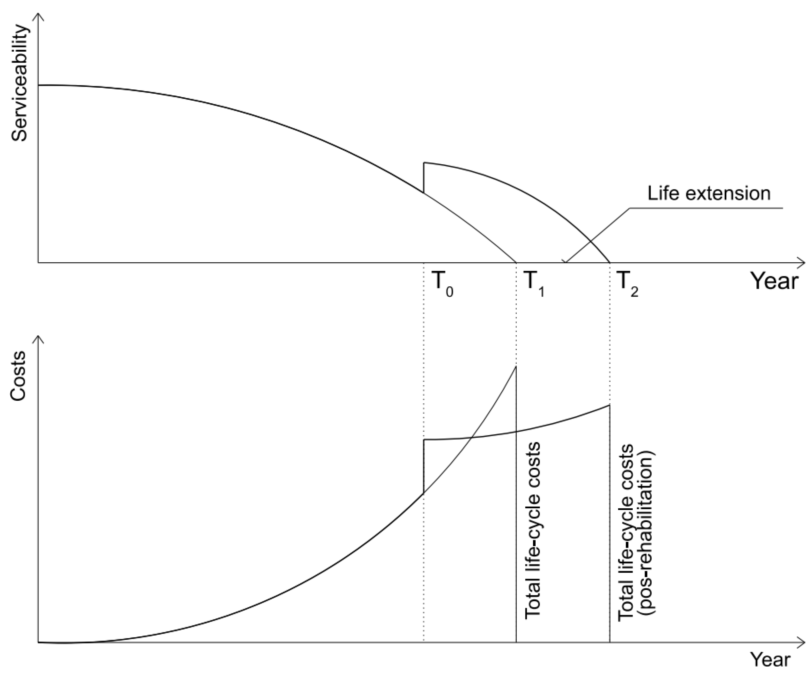
- RLCE: real life-cycle extension [year],
- T0: year of rehabilitation [year],
- T1: expected end of the life-cycle [year],
- T2: extended end of life-cycle after rehabilitation [year].
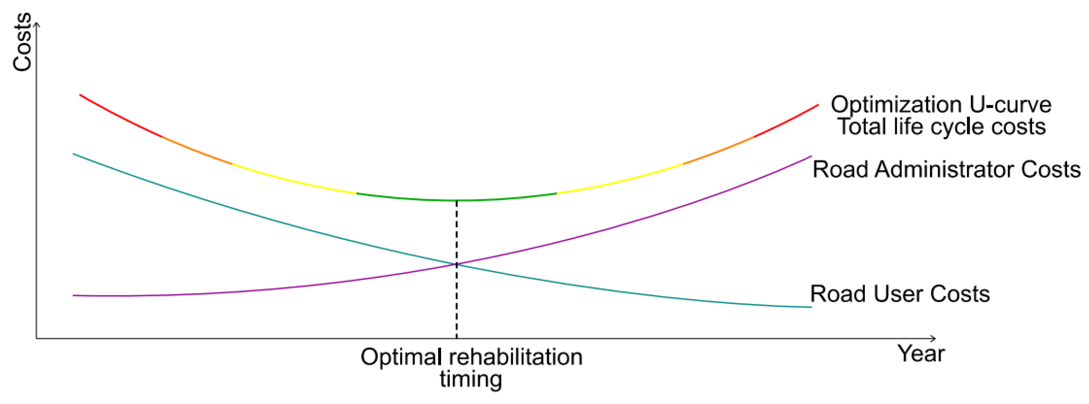
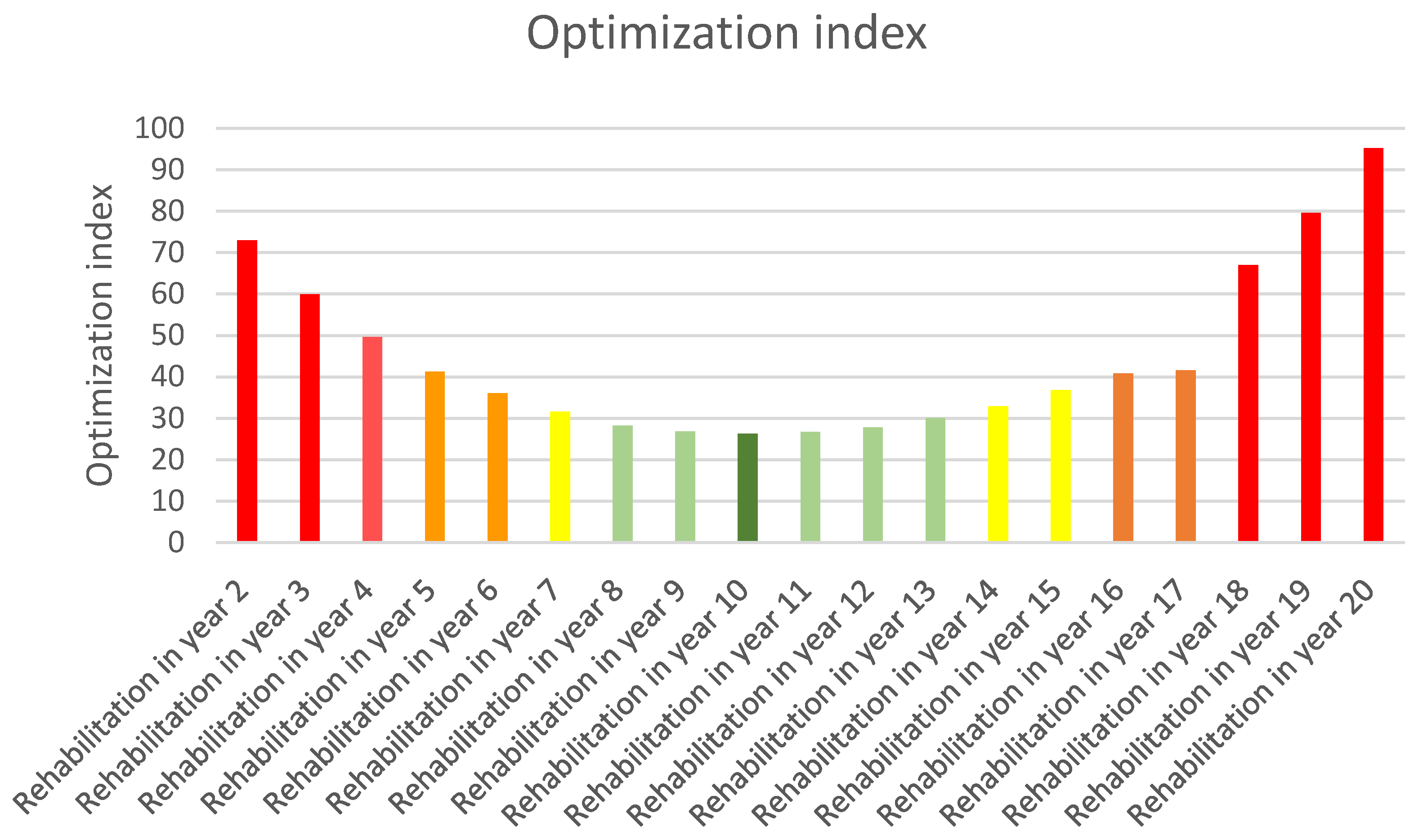
- OI: optimization index,
- RC: rehabilitation costs [€],
- NPAVBR: net present asset value before rehabilitation [€],
- NPAVAR: net present asset value after rehabilitation [€]
- Tt: extended life-cycle [€].
4. Residual Service Life and Pavement Performance Model
4.1. Residual Service Life Calculation
- Qi: temperature condition coefficient during the period “i” (0.2 winter, 0.3 summer, 0.5 spring and autumn),
- δr,i: radial stress at the lower edge of the surfacing layer, which arises in the period “i” when loaded by the design axle [MPa],
- Ri,I: calculated value of the flexural tensile strength of the material under consideration for the conditions in period “i” [MPa] normatively prescribed for new pavements or experimentally measured on samples from existing pavements,
- n: number of standard axle load cycles,
- SN: fatigue coefficient.
- ε0j: maximum amplitude ordinate of proportional deformation during the test conditions at the beginning of the test,
- a, b: fatigue parameters measured during the fatigue tests is the stress lines coefficient in the range of N,
- N: the number of load repetitions.
- DAL: number of design standard axle loads,
- ε6: average deformation derived from fatigue curve after 106 loading cycles in microstrain [µm/m],
- εj: calculated relative deformation at the bottom of the bituminous bound sub-layer in the pavement construction (based on a multilayer system in homogenous half-space, calculation model with input values presented by Remek [54]),
- : fatigue test reliability factor—(in our case 1.6 in the line with [55]).
- B: fatigue characteristics—falling gradient of the fatigue line, B = −1/b.
4.2. Pavement Performance Models
- Pt: relative value of performance parameter in relation to time t,
- t: time from the beginning of the life-cycle [years],
- T: predicted life expectancy of the pavement in terms of the performance parameter [years],
- Pn: relative value of performance parameter in relation to traffic load,
- n: standard axle load cycles from the beginning of the life cycle [SAL],
- N: predicted life expectancy of the pavement in terms of the performance parameter [SAL],
- A: coefficient of pavement class and paving materials 0 < A ≤ 1,
- B: coefficient of degradation shape of performance parameter 0.2 < B ≤ 6.0.
5. Case Study—Practical Application
6. Conclusions
- definition of the road administrator organization’s goals; these should be measurable and attainable within a specified time,
- changes in the road administrator organizational structure with regard to the needs of the asset management system,
- identification of the road administrator requirements, e.g., legal, financial, but mainly personal, due to high requirements on an understanding of PMS and AM procedures and techniques
- accelerated pavement testing capabilities; if this is not available, road database that has been in operation for 20 years or longer with enough data to use regression analysis to derive pavement performance models for main pavement parameters and most used pavement classes,
- material testing equipment and calculation methods to derive fatigue characteristics of frequently used paving materials that can be used to calculate bearing capacity and residual service life of pavements,
- risk management to evaluate and react to risks related to the implementation process.
Author Contributions
Funding
Institutional Review Board Statement
Informed Consent Statement
Data Availability Statement
Conflicts of Interest
References
- Wu, K. Development of PCI-Based Pavement Performance Model for Management of Road Infrastructure System; Arizona State University: Arizona, AZ, USA, 2015; Available online: https://repository.asu.edu/attachments/163996/content/Wu_asu_0010N_15506.pdf (accessed on 29 June 2021).
- Ferreira, A. Selection of pavement performance models for use in the Portuguese PMS. Int. J. Pavement Eng. 2011, 12, 87–97. [Google Scholar] [CrossRef]
- Gupta, A.; Kumar, P.; Rastogi, R. Critical Review of Flexible Pavement Performance Models. KSCE J. Civ. Eng. 2014, 18, 142–148. [Google Scholar] [CrossRef]
- Mikolaj, J.; Schlosser, F.; Remek, L.; Chytcakova, A. Asphalt Concrete Mixtures: Requirements with Regard to Life Cycle Assessment. Adv. Mater. Sci. Eng. 2015, 2015, 567238. [Google Scholar] [CrossRef] [Green Version]
- Martin, T.; Choummanivong, L. The Benefits of Long-Term Pavement Performance (LTPP) Research to Funders. Transp. Res. Procedia 2016, 15, 2477–2486. [Google Scholar] [CrossRef] [Green Version]
- Mikolaj, J.; Remek, L.; Macula, M. Asphalt concrete overlay optimization based on pavement performance models. Adv. Mater. Sci. Eng. 2017, 2017, 6063508. [Google Scholar] [CrossRef] [Green Version]
- Remek, L.; Mikolaj, J.; Skarupa, M. Accelerated Pavement Testing in Slovakia: APT Tester 105-03-1. Procedia Eng. 2017, 192, 765–770. [Google Scholar] [CrossRef]
- Mikolaj, J.; Remek, L.; Kozel, M. Life Cycle Extension of a Pavement Structure. Commun.-Sci. Lett. Univ. Zilina 2016, 18, 83–89. [Google Scholar] [CrossRef]
- Talvik, O.; Aavik, A. Use of FWD deflection basin parameters (sci, bdi, bci) for pavement condition assessment. Balt. J. Road Bridge Eng. 2009, 4, 196–202. [Google Scholar] [CrossRef]
- Zhang, X.; Otto, F.; Oeser, M. Pavement moduli back-calculation using artificial neural network and genetic algorithms. Constr. Build. Mater. 2021, 287, 123026. [Google Scholar] [CrossRef]
- Choi, J.W.; Wu, R.; Pestana, J.M.; Harvey, J. New Layer-Moduli Back-Calculation Method Based on the Constrained Extended Kalman Filter. J. Transp. Eng. 2010, 136, 20–30. [Google Scholar] [CrossRef]
- Xiao, F.; Xiang, Q.; Hou, X.; Amirkhanian, S. Utilization of traffic speed deflectometer for pavement structural evaluations. Measurement 2021, 178, 109326. [Google Scholar] [CrossRef]
- American Association of State Highway and Transportation Officials (AASHTO). Mechanistic-Empirical Pavement Design Guide: A Manual of Practice, Interim ed.; American Association of State Highway and Transportation Officials (AASHTO): Washington, DC, USA, 2008. [Google Scholar]
- Li, Q.; Xiao, D.X.; Wang, K.C.P.; Hall, K.D.; Qiu, Y. Mechanistic-empirical pavement design guide (MEPDG): A bird’s-eye view. J. Mod. Transp. 2011, 19, 114–133. [Google Scholar] [CrossRef] [Green Version]
- Oh, J.; Fernando, E.; Holzschuher, C.; Horhota, D. Comparison of resilient modulus values for Florida flexible mechanistic-empirical pavement design. Int. J. Pavement Eng. 2012, 13, 472–484. [Google Scholar] [CrossRef]
- Sartori, D.; Catalano, G.; Genco, M.; Pancotti, C.; Sirtori, E.; Vignetti, S.; Del Bo, C. Guide to Cost-Benefit Analysis of Investment Projects; Publications Office of the European Union: Luxembourg, 2015; ISBN 978-92-79-34796-2. [Google Scholar] [CrossRef]
- Meneses, S.; Ferreira, A. Flexible pavement maintenance programming considering the minimisation of maintenance and rehabilitation costs and the maximisation of the residual value of pavements. Int. J. Pavement Eng. 2014, 16, 571–586. [Google Scholar] [CrossRef]
- Life-Cycle Cost Analysis Procedures Manual: State of California Department of Transportation Division of Maintenance Pavement Program. 2013. Available online: https://dot.ca.gov/-/media/dot-media/programs/maintenance/documents/office-of-concrete-pavement/life-cycle-cost-analysis/lcca-25ca-manual-final-aug-1-2013-v2-a11y.pdf (accessed on 26 August 2022).
- Wu, D.; Yuan, C.; Kumfer, W.; Liu, H. A life-cycle optimization model using semi-markov process for highway bridge maintenance. Appl. Math. Model. 2017, 43, 45–60. [Google Scholar] [CrossRef]
- Mandapaka, V.; Basheer, I.; Sahasi, K.; Ullidtz, P.; Harvey, J.T.; Sivaneswaran, N. Mechanistic-Empirical and Life-Cycle Cost Analysis for Optimizing Flexible Pavement Maintenance and Rehabilitation. J. Transp. Eng. 2012, 138, 625–633. [Google Scholar] [CrossRef]
- Saad, D.A.; Hegazy, T. Enhanced benefit–cost analysis for infrastructure fund allocation. Can. J. Civ. Eng. 2015, 42, 89–97. [Google Scholar] [CrossRef]
- Jorge, D.; Ferreira, A. Road network pavement maintenance optimisation using the HDM-4 pavement performance prediction models. Int. J. Pavement Eng. 2012, 13, 39–51. [Google Scholar] [CrossRef]
- Chen, W.; Zheng, M. Multi-objective optimization for pavement maintenance and rehabilitation decision-making: A critical review and future directions. Autom. Constr. 2021, 130, 103840. [Google Scholar] [CrossRef]
- Santos, J.; Ferreira, A.; Flintsch, G. A life cycle assessment model for pavement management: Road pavement construction and management in Portugal. Int. J. Pavement Eng. 2014, 16, 315–336. [Google Scholar] [CrossRef]
- Alyami, Z.; Tighe, S.L. Development of Maintenance and Rehabilitation Program: Pavement Assets Under Performance-Based Contracts. Transp. Res. Rec. 2013, 2361, 1–10. [Google Scholar] [CrossRef]
- Khurshid, M.B.; Irfan, M.; Labi, S. Optimal Performance Threshold Determination for Highway Asset Interventions: Analytical Framework and Application. J. Transp. Eng. 2011, 137, 128–139. [Google Scholar] [CrossRef]
- Van Der Velde, J.; Klatter, L.; Bakker, J. A holistic approach to asset management in the Netherlands. Struct. Infrastruct. Eng. 2013, 9, 340–348. [Google Scholar] [CrossRef]
- Falls, L.C.; Haas, R.; McNeil, S.; Tighe, S. Asset Management and Pavement Management: Using Common Elements to Maximize Overall Benefits. Transp. Res. Rec. 2001, 1769, 1–9. [Google Scholar] [CrossRef]
- Mikolaj, J.; Remek, Ľ.; Kozel, M. Road Asset Value Calculation Based on Asset Performance, Community Benefits and Technical Condition. Sustainability 2022, 14, 4375. [Google Scholar] [CrossRef]
- Piarc Asset Management Manual: A Guide for Practitioners. Available online: https://road-asset.piarc.org/en (accessed on 26 August 2022).
- Kokot, D. Common Framework for a European Life, Cycle Based Asset Management Approach for Transport Infrastructure Networks. Routes/Roads 2019, 2, 27–29. [Google Scholar]
- Godau, R. Why asset management should be a corporate function. J. Public Work. Infrastruct. 2008, 1, 171–184. [Google Scholar]
- Di Ciommo, F.; Shiftan, Y. Transport equity analysis. Transp. Rev. 2017, 37, 139–151. [Google Scholar] [CrossRef] [Green Version]
- AM4INFRA. 2018. Available online: www.am4infra.eu (accessed on 26 August 2020).
- Organisation For Economic Co-Operation and Development OECD. Asset Management for the Roads Sector. In Road Transport and Intermodal Linkages Research Programme; OECD Publishing: Paris, France, 2001; ISSN 19900384. [Google Scholar] [CrossRef]
- U.S. Department of Transportation; Federal Highway Administration. Asset Management Primer; Office of Asset Management: Washington, DC, USA, 1999; p. 30.
- Premius, H. The Infrastructure We Ride on. Decision Making in Transportation Investment. Transp. Rev. 2019, 39, 560–562. [Google Scholar] [CrossRef]
- Jafino, B.A.; Kwakkel, J.; Verbraeck, A. Transport network criticality metrics: A comparative analysis and a guideline for selection. Transp. Rev. 2020, 40, 241–264. [Google Scholar] [CrossRef]
- Nicolosi, V. Multi–Objective Approaches to Cross-Asset Resource Allocation in Transportation Asset Management. Routes/Roads 2019, 2, 1–7. [Google Scholar]
- Essen, H.; Fiorello, D.; El Beyrouty, K.; Bieler, C.; Wijngaarden, L. Handbook on the External Costs of Transport: Version 2019–1.1; Publications Office of the European Union: Luxembourg, 2020; ISBN 978-92-76-18184-2. [Google Scholar] [CrossRef]
- Piryonesi, S.M.; El-Diraby, T.E. Data Analytics in Asset Management: Cost-Effective Prediction of the Pavement Condition Index. J. Infrastruct. Syst. 2020, 26, 04019036. [Google Scholar] [CrossRef]
- National Academies of Sciences, Engineering and Medicine. Case Studies in Cross-Asset, Multi-Objective Resource Allocation; The National Academies Press: Washington, DC, USA, 2019. [Google Scholar] [CrossRef]
- American Association of State Highway and Transportation Officials (AASHTO). Defining Cross-Asset Decision Making: A Discussion Paper (TAM ETG); Report Number: TAM-ETG-2015-PDL-003; American Association of State Highway and Transportation Officials: Washington, DC, USA, 2015. [Google Scholar]
- HDM-4 Software; World Road Association PIARC: Paris, France, 2000. Available online: https://www.piarc.org/en/PIARC-knowledge-base-Roads-and-Road-Transportation/Road-Safety-Sustainability/Road-Assets-Management/HDM-4-Software (accessed on 26 August 2022).
- RoSy® Road Systems. Available online: http://www.eltrap.co.il/image.ashx?i=603006.pdf&fn=612873-2.pdf (accessed on 26 August 2022).
- Schlosser, F.; Mikolaj, J.; Zatkalikova, V.; Sramek, J.; Durekova, D.; Remek, L. Deformation Properties and Fatigue of Bituminous Mixtures. Adv. Mater. Sci. Eng. 2013, 2013, 701764. [Google Scholar] [CrossRef] [Green Version]
- Schlosser, F.; Sramekova, E.; Šrámek, J. Rheology, Deformational Properties and Fatigue of the Asphalt Mixtures. Adv. Mater. Res. 2014, 875–877, 578–583. [Google Scholar] [CrossRef]
- Gerrard, C.M. Tables of stresses, strains and displacements in two-layer elastic systems under various traffic loads. Aust. Road Res. Board 1969, 3, 157. [Google Scholar]
- Burmister, D.M. The General Theory of Stresses and Displacements in Layered Systems. I. J. Appl. Phys. 1945, 16, 89–94. [Google Scholar] [CrossRef]
- Gupta, P.K.; Walowit, J.A. Contact stresses between an elastic cylinder and a layered elastic solid. J. Lubr. Technol. 1974, 96, 250–257. [Google Scholar] [CrossRef]
- Perriot, A.; Barthel, E. Elastic contact to a coated half-space: Effective elastic modulus and real penetration. J. Mater. Res. 2004, 19, 600–608. [Google Scholar] [CrossRef]
- BS EN 12697-24:2003; Bituminous Mixtures—Test Method for Hot Mix Asphalt–Part 24: Resistant to Fatigue. European Committee for Standardization (Cen): Brussels, Belgium, 2003.
- Ministerstvo Dopravy České Republiky, Navrhování Vozovek Pozemích Komunikac, TP170. 2006. Available online: https://pjpk.rsd.cz/data/USR_001_2_8_TP/TP_170_upraveny_dotisk.pdf (accessed on 4 October 2022).
- Remek, L.; Valašková, V. Data Gathering and Evaluation of Tensile Strains Measured in APT with Mathematical Computation Method. In Accelerated Pavement Testing to Transport Infrastructure Innovation; Springer: Cham, Switzerland, 2020. [Google Scholar] [CrossRef]
- Sramek, J. Stiffness and Fatigue of Asphalt Mixtures for Pavement Construction. Slovak J. Civ. Eng. 2018, 26, 24–29. [Google Scholar] [CrossRef]
- Decký, M.; Drusa, M.; Papán, D.; Šrámek, J. The Relationship between Dynamic and Static Deformation Modulus of Unbound Pavement Materials Used for Their Quality Control Methodology. Materials 2022, 15, 2922. [Google Scholar] [CrossRef]
- BS EN 13285:2018; Road Construction Materials: Unbound Mixtures-Specifications. European Committee for Standardization (Cen): Brussels, Belgium, 2018; p. 32ISBN 978 0 580 87151 1.
- Ministerstvo Dopravy Pôšt a Telekomunikácií SR, Navrhoivanie Netuhých a Polotuhých Vozoviek, TP3/2009. 2009. Available online: https://www.ssc.sk/files/documents/technicke-predpisy/tp/tp_033.pdf (accessed on 4 October 2022).
- Research Institute of Engineering Constructions. Phase 3 Assessment of Pavement Performance and Its Development; Report no. 05-514-904 04; Research Institute of Engineering Constructions: Bratislava, Slovakia, 1993. [Google Scholar]


| Parameter | A0 | B | b | ε6 |
|---|---|---|---|---|
| Fatigue values | −19.0452 | −6.3656 | −0.1571 | 116.29 |
| Layer | Complex Modulus | Strength | Poisson Number | Layer Thickness |
|---|---|---|---|---|
| Surface course AC 11 | 7577 | 3.2 MPa | 0.33 | 40 mm |
| Base course AC 16 | 9967 | 2.4 MPa | 0.33 | 80 mm |
| Mechanically bound aggregate, 31,5 | 586 | 0.1 MPa | 0.30 | 180 mm |
| Gravel Sub-base, 31,5 | 365 | 0.07 MPa | 0.30 | 200 mm |
| Sub-grade | 100 | - | 0.35 | - |
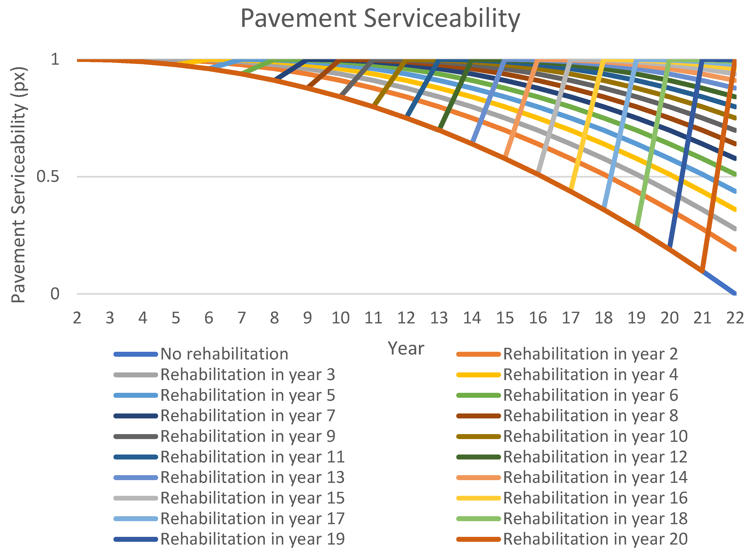
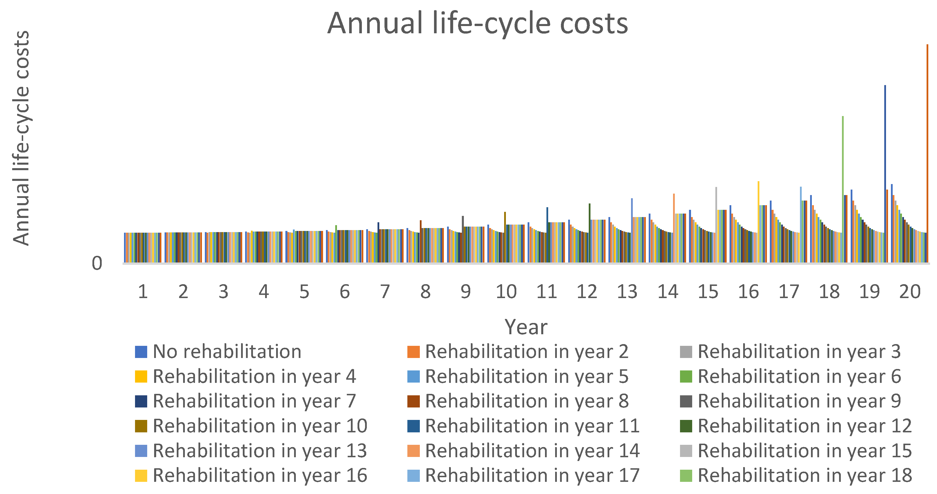
| Year | Rehabilitation technology | 0 | 1 | 2 | 3 | 4 | 5 | 6 | 7 | 8 | 9 | 10 | 11 | 12 | 13 | 14 | 15 | 16 | 17 | 18 | 19 | 20 | Average pavement serviceability during life-cycle |
| Pavement serviceability—IRI | 0 | 0.04 | 0.16 | 0.36 | 0.64 | 1 | 1.44 | 1.96 | 2.56 | 3.24 | 4 | 4.84 | 5.76 | 6.76 | 7.84 | 9 | 10.24 | 11.56 | 12.96 | 14.44 | 16 | ||
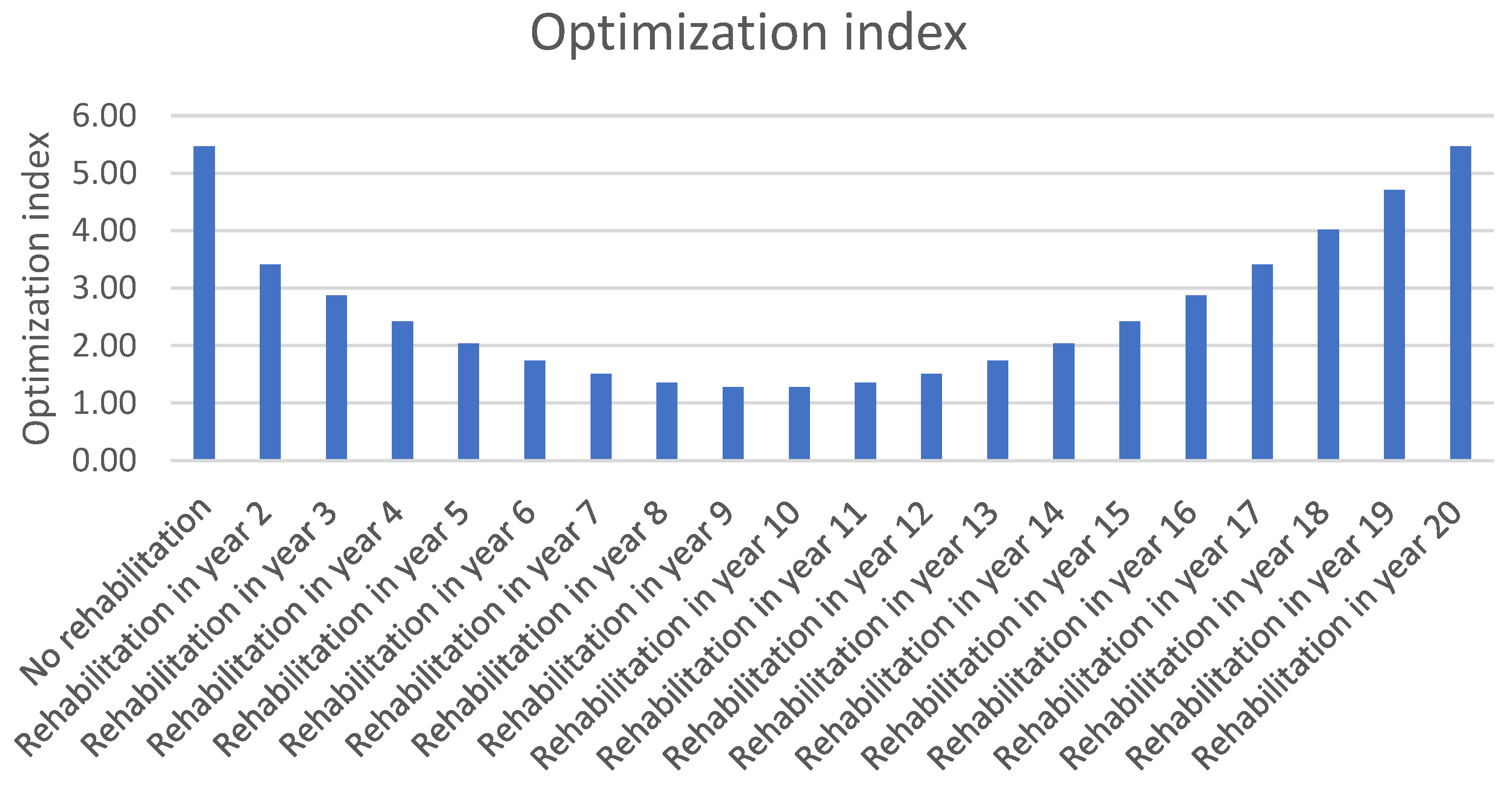
| No rehabilitation | No rehabilitation | 0 | 0.04 | 0.16 | 0.36 | 0.64 | 1 | 1.44 | 1.96 | 2.56 | 3.24 | 4 | 4.84 | 5.76 | 6.76 | 7.84 | 9 | 10.24 | 11.56 | 12.96 | 14.44 | 16 | 5.47 |
| Rehabilitation in year 2 | Rejuvenation | 0 | 0.04 | 0.16 | 0 | 0.04 | 0.16 | 0.36 | 0.64 | 1 | 1.44 | 1.96 | 2.56 | 3.24 | 4 | 4.84 | 5.76 | 6.76 | 7.84 | 9 | 10.24 | 11.56 | 3.41 |
| Rehabilitation in year 3 | Rejuvenation+ | 0 | 0.04 | 0.16 | 0.36 | 0 | 0.04 | 0.16 | 0.36 | 0.64 | 1 | 1.44 | 1.96 | 2.56 | 3.24 | 4 | 4.84 | 5.76 | 6.76 | 7.84 | 9 | 10.24 | 2.88 |
| Rehabilitation in year 4 | Dressing 1 layer | 0 | 0.04 | 0.16 | 0.36 | 0.64 | 0 | 0.04 | 0.16 | 0.36 | 0.64 | 1 | 1.44 | 1.96 | 2.56 | 3.24 | 4 | 4.84 | 5.76 | 6.76 | 7.84 | 9 | 2.42 |
| Rehabilitation in year 5 | Dressing 2 layers | 0 | 0.04 | 0.16 | 0.36 | 0.64 | 1 | 0 | 0.04 | 0.16 | 0.36 | 0.64 | 1 | 1.44 | 1.96 | 2.56 | 3.24 | 4 | 4.84 | 5.76 | 6.76 | 7.84 | 2.04 |
| Rehabilitation in year 6 | Thin overlay 20 mm | 0 | 0.04 | 0.16 | 0.36 | 0.64 | 1 | 1.44 | 0 | 0.04 | 0.16 | 0.36 | 0.64 | 1 | 1.44 | 1.96 | 2.56 | 3.24 | 4 | 4.84 | 5.76 | 6.76 | 1.73 |
| Rehabilitation in year 7 | Thin overlay 30 mm | 0 | 0.04 | 0.16 | 0.36 | 0.64 | 1 | 1.44 | 1.96 | 0 | 0.04 | 0.16 | 0.36 | 0.64 | 1 | 1.44 | 1.96 | 2.56 | 3.24 | 4 | 4.84 | 5.76 | 1.50 |
| Rehabilitation in year 8 | Mill & Replace 20 mm & 30 mm | 0 | 0.04 | 0.16 | 0.36 | 0.64 | 1 | 1.44 | 1.96 | 2.56 | 0 | 0.04 | 0.16 | 0.36 | 0.64 | 1 | 1.44 | 1.96 | 2.56 | 3.24 | 4 | 4.84 | 1.35 |
| Rehabilitation in year 9 | Mill & Replace 40 mm & 50 mm | 0 | 0.04 | 0.16 | 0.36 | 0.64 | 1 | 1.44 | 1.96 | 2.56 | 3.24 | 0 | 0.04 | 0.16 | 0.36 | 0.64 | 1 | 1.44 | 1.96 | 2.56 | 3.24 | 4 | 1.28 |
| Rehabilitation in year 10 | Mill & Replace 50 mm & 60 mm | 0 | 0.04 | 0.16 | 0.36 | 0.64 | 1 | 1.44 | 1.96 | 2.56 | 3.24 | 4 | 0 | 0.04 | 0.16 | 0.36 | 0.64 | 1 | 1.44 | 1.96 | 2.56 | 3.24 | 1.28 |
| Rehabilitation in year 11 | Mill & Replace 60 mm & 70 mm | 0 | 0.04 | 0.16 | 0.36 | 0.64 | 1 | 1.44 | 1.96 | 2.56 | 3.24 | 4 | 4.84 | 0 | 0.04 | 0.16 | 0.36 | 0.64 | 1 | 1.44 | 1.96 | 2.56 | 1.35 |
| Rehabilitation in year 12 | Mill & Replace 70 mm & 90 mm | 0 | 0.04 | 0.16 | 0.36 | 0.64 | 1 | 1.44 | 1.96 | 2.56 | 3.24 | 4 | 4.84 | 5.76 | 0 | 0.04 | 0.16 | 0.36 | 0.64 | 1 | 1.44 | 1.96 | 1.50 |
| Rehabilitation in year 13 | Mill & Replace 80 mm & 120 mm | 0 | 0.04 | 0.16 | 0.36 | 0.64 | 1 | 1.44 | 1.96 | 2.56 | 3.24 | 4 | 4.84 | 5.76 | 6.76 | 0 | 0.04 | 0.16 | 0.36 | 0.64 | 1 | 1.44 | 1.73 |
| Rehabilitation in year 14 | Mill & Replace 100 mm & 140 mm | 0 | 0.04 | 0.16 | 0.36 | 0.64 | 1 | 1.44 | 1.96 | 2.56 | 3.24 | 4 | 4.84 | 5.76 | 6.76 | 7.84 | 0 | 0.04 | 0.16 | 0.36 | 0.64 | 1 | 2.04 |
| Rehabilitation in year 15 | Mill & Replace 120 mm & 180 mm | 0 | 0.04 | 0.16 | 0.36 | 0.64 | 1 | 1.44 | 1.96 | 2.56 | 3.24 | 4 | 4.84 | 5.76 | 6.76 | 7.84 | 9 | 0 | 0.04 | 0.16 | 0.36 | 0.64 | 2.42 |
| Rehabilitation in year 16 | Mill & Replace 150 mm & 200 mm | 0 | 0.04 | 0.16 | 0.36 | 0.64 | 1 | 1.44 | 1.96 | 2.56 | 3.24 | 4 | 4.84 | 5.76 | 6.76 | 7.84 | 9 | 10.24 | 0 | 0.04 | 0.16 | 0.36 | 2.88 |
| Rehabilitation in year 17 | Surfacing replacement | 0 | 0.04 | 0.16 | 0.36 | 0.64 | 1 | 1.44 | 1.96 | 2.56 | 3.24 | 4 | 4.84 | 5.76 | 6.76 | 7.84 | 9 | 10.24 | 11.56 | 0 | 0.04 | 0.16 | 3.41 |
| Rehabilitation in year 18 | Surfacing + Base Course replacement | 0 | 0.04 | 0.16 | 0.36 | 0.64 | 1 | 1.44 | 1.96 | 2.56 | 3.24 | 4 | 4.84 | 5.76 | 6.76 | 7.84 | 9 | 10.24 | 11.56 | 12.96 | 0 | 0.04 | 4.02 |
| Rehabilitation in year 19 | Surfacing + Base + Sub-base Course replacement | 0 | 0.04 | 0.16 | 0.36 | 0.64 | 48 | 1.44 | 1.96 | 2.56 | 3.24 | 4 | 4.84 | 5.76 | 6.76 | 7.84 | 9 | 10.24 | 11.56 | 12.96 | 14.44 | 0 | 6.94 |
| Rehabilitation in year 20 | Total reconstruction | 0 | 0.04 | 0.16 | 0.36 | 0.64 | 1 | 1.44 | 1.96 | 2.56 | 3.24 | 4 | 4.84 | 5.76 | 6.76 | 7.84 | 9 | 10.24 | 11.56 | 12.96 | 14.44 | 16 | 5.47 |
Publisher’s Note: MDPI stays neutral with regard to jurisdictional claims in published maps and institutional affiliations. |
© 2022 by the authors. Licensee MDPI, Basel, Switzerland. This article is an open access article distributed under the terms and conditions of the Creative Commons Attribution (CC BY) license (https://creativecommons.org/licenses/by/4.0/).
Share and Cite
Mikolaj, J.; Remek, Ľ.; Kozel, M. Optimization of Bituminous Road Surfacing Rehabilitations Based on Optimization of Road Asset Value. Appl. Sci. 2022, 12, 10466. https://doi.org/10.3390/app122010466
Mikolaj J, Remek Ľ, Kozel M. Optimization of Bituminous Road Surfacing Rehabilitations Based on Optimization of Road Asset Value. Applied Sciences. 2022; 12(20):10466. https://doi.org/10.3390/app122010466
Chicago/Turabian StyleMikolaj, Ján, Ľuboš Remek, and Matúš Kozel. 2022. "Optimization of Bituminous Road Surfacing Rehabilitations Based on Optimization of Road Asset Value" Applied Sciences 12, no. 20: 10466. https://doi.org/10.3390/app122010466
APA StyleMikolaj, J., Remek, Ľ., & Kozel, M. (2022). Optimization of Bituminous Road Surfacing Rehabilitations Based on Optimization of Road Asset Value. Applied Sciences, 12(20), 10466. https://doi.org/10.3390/app122010466


