Article

Research on Strata Deformation Induced by EPB Tunneling in Round Gravel Stratum and Its Control Technology

1
Institute of Geotechnical Engineering, Zhejiang University of Technology, Hangzhou 310014, China
2
Hangzhou Municipal Facilities Management Center, Hangzhou 310005, China
3
Tengda Construction Group Co., Ltd., Shanghai 200120, China
*
Author to whom correspondence should be addressed.
Appl. Sci. 2022, 12(20), 10553; https://doi.org/10.3390/app122010553
Submission received: 26 September 2022 / Revised: 15 October 2022 / Accepted: 17 October 2022 / Published: 19 October 2022

Abstract

:
Recently, many studies have been conducted on the stratum deformation induced by earth pressure balance (EPB) shield tunneling in soft soil and sand. Movement laws vary largely among different strata. However, at present, relevant research mainly focuses on soft soil and sand, whereas little attention has been paid to the movement law of round gravel stratum with higher instability. In this study, a field monitoring test was carried out on the EPB shield machine when it passes through the round gravel stratum. Based on the analysis of monitoring results under different chamber earth pressures, thrust force, the torque of the cutter, grouting pressure, and grouting volume, the relationships between shield tunneling parameters and their influence on the disturbance of the surrounding soil mass were investigated. It was found that the surface deformation shape of the monitoring section of the south and north lines conforms to the Gaussian curve. The vertical deformation of the stratum at the tunnel axis is the largest. The maximum value is observed when the cutter head reaches the monitoring section. The horizontal deformation reaches a maximum value at the stage of the shield tail pass section. The strata deformation is not only related to the strata properties but also has a strong positive correlation with the shield tunneling parameters. The chamber earth pressure is the main factor affecting the stratum deformation before the arrival of the cutter head, and the grouting volume is the main factor affecting the strata deformation during the stage of the shield tail pass section.

1. Introduction

With the rapid evolvement of the Chinese economy and the acceleration of urbanization, the development of urban rail transit has become one of the main approaches to alleviate urban traffic pressure. According to statistical research, 50 cities in mainland China launched urban rail transit by the end of 2021, covering a total distance of 9192.62 km, of which 7253.73 km was covered by subways, accounting for 78.9%. EPB shield machine excavation is widely used in urban subway tunnel construction because of its fast construction progress and high degree of mechanization. However, tunneling inevitably breaks the original balance state of the surrounding soil layers, which causes soil stress redistribution and additional deformation of the surrounding buildings (structures).
In recent decades, many experts and scholars have studied the law of soil movement induced by EPB shields when they pass through different strata. Wen [1] found that when EPB shields pass through different strata, the degree of disturbance to the surrounding soil layers is also different. Therefore, they correspondingly proposed shield control measures to reduce soil movement.
At present, most of the strata studies mainly focus on soft clay strata, which have remarkable engineering characteristics such as high water content, low shear strength, high sensitivity, high compressibility, and significantly reduced strength after disturbance [2]. The study on the impact of the London subway tunnel excavation on the surrounding environment became a typical engineering example in soft clay areas [3,4,5,6,7,8].
According to field monitoring results, the soil will move “outward” in the radial direction when the EPB shield machine passes through the monitoring section. The ground surface will heave first and then settle, which is mainly controlled by the surface pressure and shield tail grouting pressure [7]. However, Wan et al. [8] monitored the strata displacements caused by EPB tunneling with a large burial depth. The results showed that the soil had an inward displacement, which is opposite to the “outward” displacement [7]. This result shows that the burial depth is also a key factor affecting the displacement of the strata. Similar phenomena were also observed in the Jubilee Line Extension (JLE) project.
Many scholars have carried out research in the coastal area of eastern China as a typical shield tunnel project in a soft soil area. Lee et al. [9] conducted field monitoring of Shanghai Metro Line 2 and found that the earth pressure ratio (EPR) is the key factor affecting the surface heave and settlement at two diameters in front of the cutter head. Xu et al. [10] conducted a model test using Shanghai Tunnel M8 as a prototype to study the surface deformation of EPB shield tunneling. The research results show that the surface heave and settlement in front of the cutter head are related to the dumping rate, which has a high positive correlation with the ratio of the tunneling speed and the speed of the screw. Xie et al. [11] found that the surface settlement curve meets the Peck settlement curve when the large-diameter EPB crosses the soft soil area of Shanghai. Grouting pressure is also a major factor affecting surface deformation. Zhu et al. [12] monitored and analyzed the horizontal displacement of soil caused by EPB in clay. The horizontal displacement of soil is affected not only by the shield tunneling parameters but also by the soil properties of the crossing strata. It can be seen from the above research that the cutter pressure is the main factor affecting the surrounding soil deformation when an EPB shield is tunneling in soft soil.
Some scholars have also studied the stratum deformation of EPB shield tunneling in sandy pebble stratum. This stratum has low fluidity, high permeability, poor cementing ability, and high single-stone strength, which is different from the physical and mechanical properties of soft soil. Shield tunneling control is also different from soft soil, so some scholars have also conducted preliminary research on this stratum. The surface monitoring results of Chengdu Line 1 show that the surface settlement caused by the shield tunnel is mainly affected by the pressure of the cutter, the friction between the shield shell and the surrounding soil, and the gap of the shield tail. The surface deformation of the sandy pebble stratum is V-shaped, and its influence range is smaller than that of soft soil. The shield tail gap is the main reason for the ground loss [13]. Zhang et al. [14] found that the influence of grouting pressure on surface deformation is greater than that of chamber earth pressure. The weight of the shield machine and the friction between the shield machine and the surrounding soil have little influence on the ground settlement. Liu et al. [15] pointed out that surface deformation is related to the grouting pressure at the shield tail but not to the grouting volume.
The above research shows that when the shield tunneling passes through different strata, the stratum deformation law and control methods are different. Nowadays, most of the strata that EPB shields pass through are soft soil stratum, and some projects are sandy pebble stratum. There is little research on other strata. This project relies on the section from Fangxi Road station to Liansheng Road Station of Hangzhou Metro Line 3. The EPB crossing stratum in this section is mainly a round gravel stratum. The round gravel stratum is mainly composed of gravel, pebble, and sand. The stratum has a large difference in particle size. In addition, its anisotropy is greater than that of the soft soil layer and sandy pebble stratum. It is an unstable layer that is therefore prone to collapse when disturbed. In order to explore the law of stratum deformation and the control methods to reduce formation deformation during EPB shield tunneling in round gravel stratum, systematic, close-up, and high-density field monitoring tests were carried out in this section. This research provides beneficial information for engineering similar projects to control stratum deformation.

2. Field Test Plan

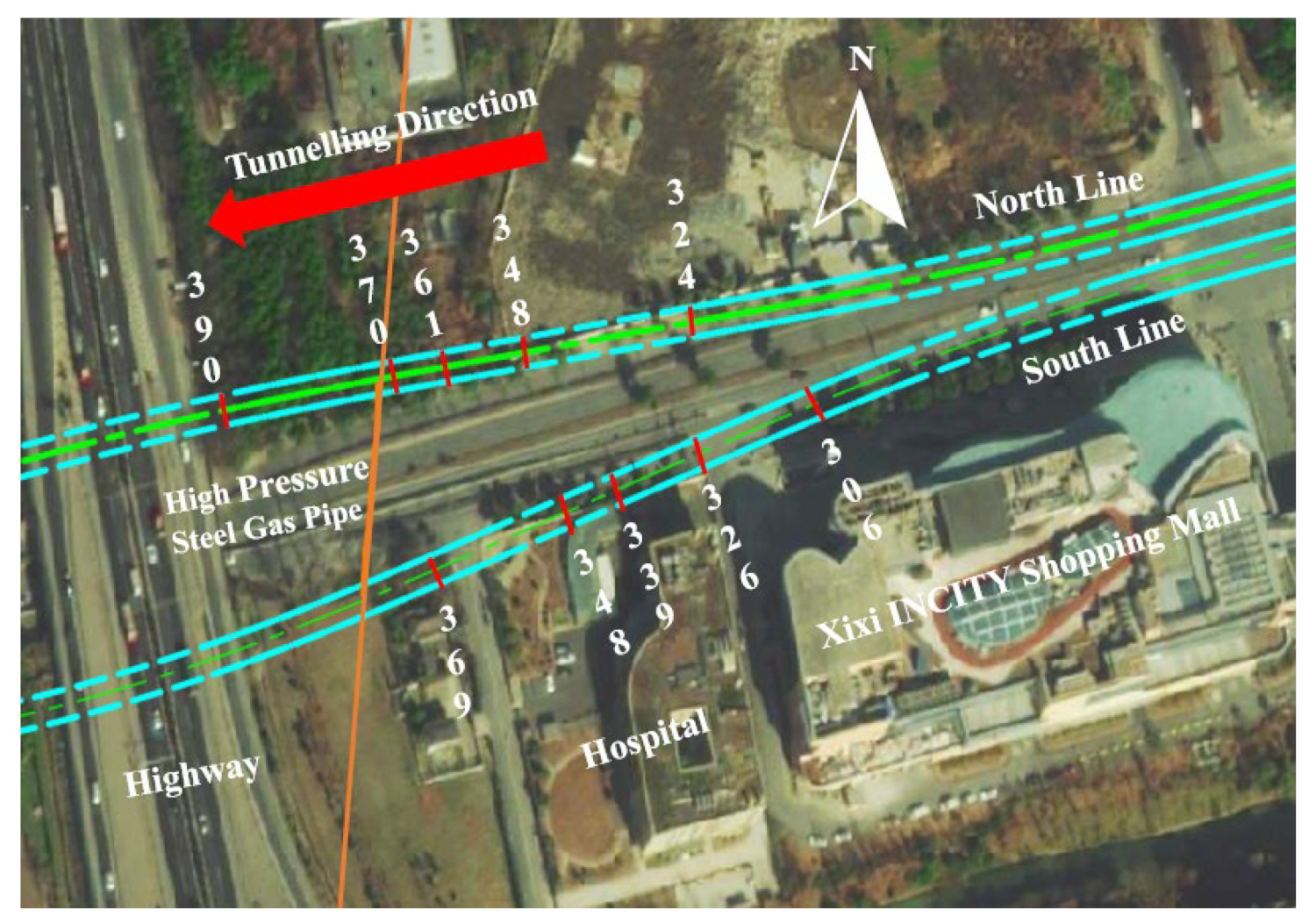
2.1. Project Overview

The Hangzhou Metro Line 3 runs between the Fangxi Road Station and Liansheng Road Station. As Figure 1 shows, the overall section is generally east–west. The longitudinal section adopts an energy-saving slope. The buried depth of both the starting point and endpoint of the tunnel is 9.9 m, and the maximum covering soil depth is 14.5 m. EPB is adopted as the shield machine. The cutter structure is a spoke and panel type, in which the opening rate is about 38%. The shield machine has an outer diameter of 6.48 m, an inner diameter of 6.2 m, and a thickness of 0.14 m. The segment has a staggered arrangement, with an outer diameter, inner diameter, width, and thickness of 6.2 m, 5.5 m, 1.2 m, and 0.35 m, respectively. The minimum curve radius of the shield tunnel is 450 m, and the distance between the north–south line is 15.8–45.5 m. The south line is the first line and the north line is the backward line. The two lines have little influence on each other during propulsion because the minimum difference in the number of rings between the two lines is about 200 rings.

2.2. Geological and Hydrological Conditions

The soil conditions in the interval mainly include: ➀2 plain fill, ➁2 silty clay, ➃1 muddy silty clay, ➄1 silty clay, ➈4 round gravel, (20)1 fully weathered argillaceous siltstone, and (20)2 medium weathered argillaceous siltstone. The burial depth of the level of the hydraulic pressure of the round gravel stratum is 1.79 m. The geological profile of the monitoring section is shown in Figure 2 (rings from No. 306 to No. 390), and the specific soil physical and mechanical parameters are shown in Table 1. According to regional data and regional construction experience, this layer has a high water volume and head and, as a result, easily suffers from engineering accidents such as sudden surges. The double line of the interval tunnel passes through the high-pressure gas pipeline. The pipeline is buried at a depth of 5.8–7.8 m, and the minimum vertical clear distance from the center of the tunnel is about 5.5 m.

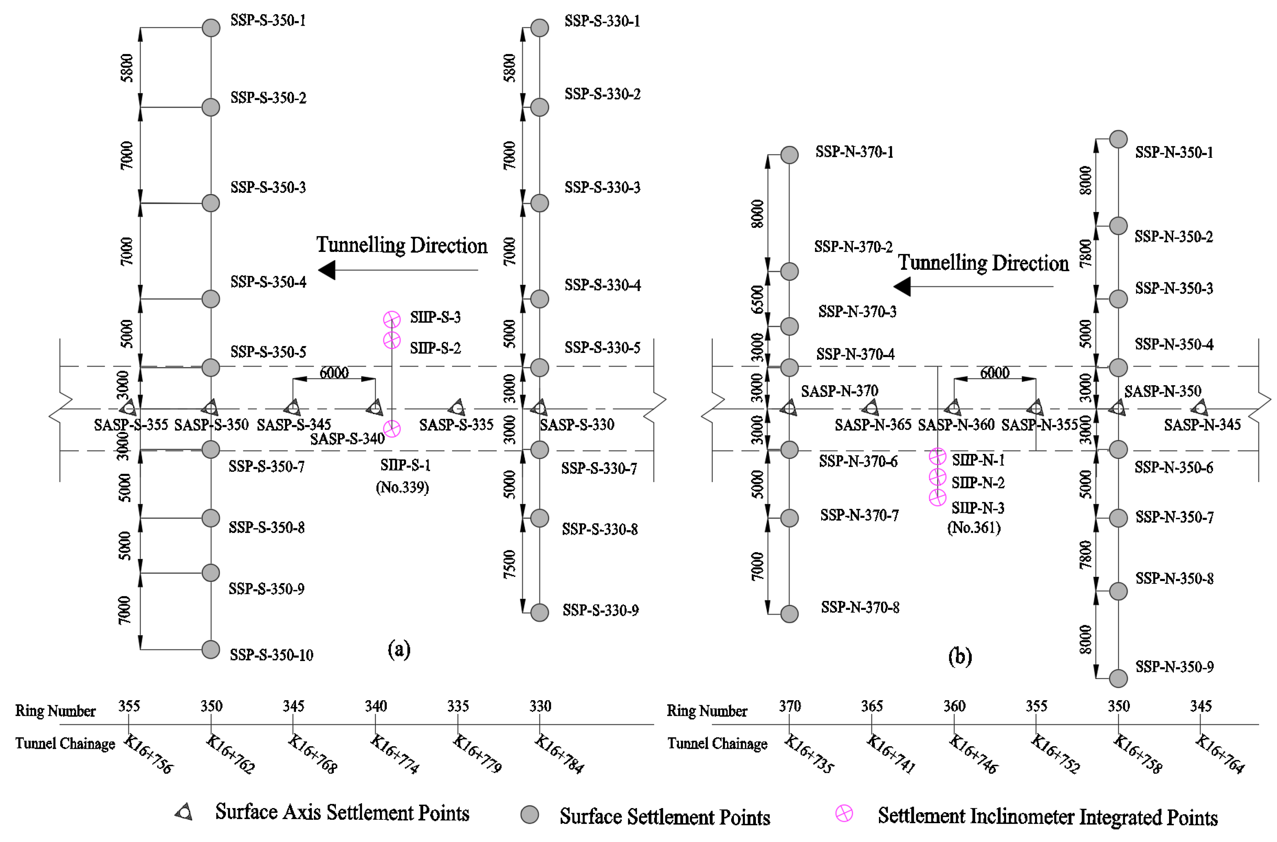
2.3. Field Monitoring Content and Layout

According to the situation of the site, and considering the convenience and accuracy of monitoring, the site monitoring point area is in the range of rings 330–370. Surface settlement points (SSP), stratum settlement points, and stratum horizontal displacement points are respectively arranged in this section. The surface axis settlement points (SASP) are arranged in intervals of five rings, and the cross-section measuring points are arranged in intervals of 20 rings. The monitoring section A of the 339 ring south line is equipped with settlement inclinometer integrated points (SIIP-S) as integrated measuring holes for stratum settlement and stratum horizontal displacement. The monitoring section B of the 361 ring north line is equipped with settlement inclinometer integrated points (SIIP-N) as integrated measuring holes for stratum settlement and stratum horizontal displacement, as shown in Figure 3 and Figure 4.
Stratum settlement monitoring method: The monitoring section A is located at the 339 ring of the south line. When the shield starts to excavate the 306 ring, the data are collected every 5 rings during the period from ring 306 to 326. During the period from ring 326 to 348, intensive monitoring is carried out, and each ring is monitored once. During this period, monitoring is performed at the end of shield tunneling–segment installation to reduce the soil disturbance caused by shield tunneling; data of rings 348–368 are collected every 10 rings, and the total number of monitoring times is 27.
Monitoring section B is located at ring 361 of the north line. Data collection starts when the shield tunneling reaches ring 324. Data are collected every 6 rings from ring 324 to 348. Intensive monitoring is carried out from ring 348 to 370, once per ring. During this period, monitoring is carried out near the end of the shield tunneling–pipe installation to reduce the disturbance caused by shield tunneling to the soil; data of rings 370–390 are collected every 10 rings, and the total number of monitoring times is 27.
Monitoring method of horizontal displacement of stratum: monitoring data of section A from ring 325 to 355 are collected every 2 rings, with a total number of 15 monitoring times. Monitoring data of section B from ring 345 to 375 are collected every 2 rings, with a total number of 15 monitoring times.

3. Measured Analysis of Stratum Deformation

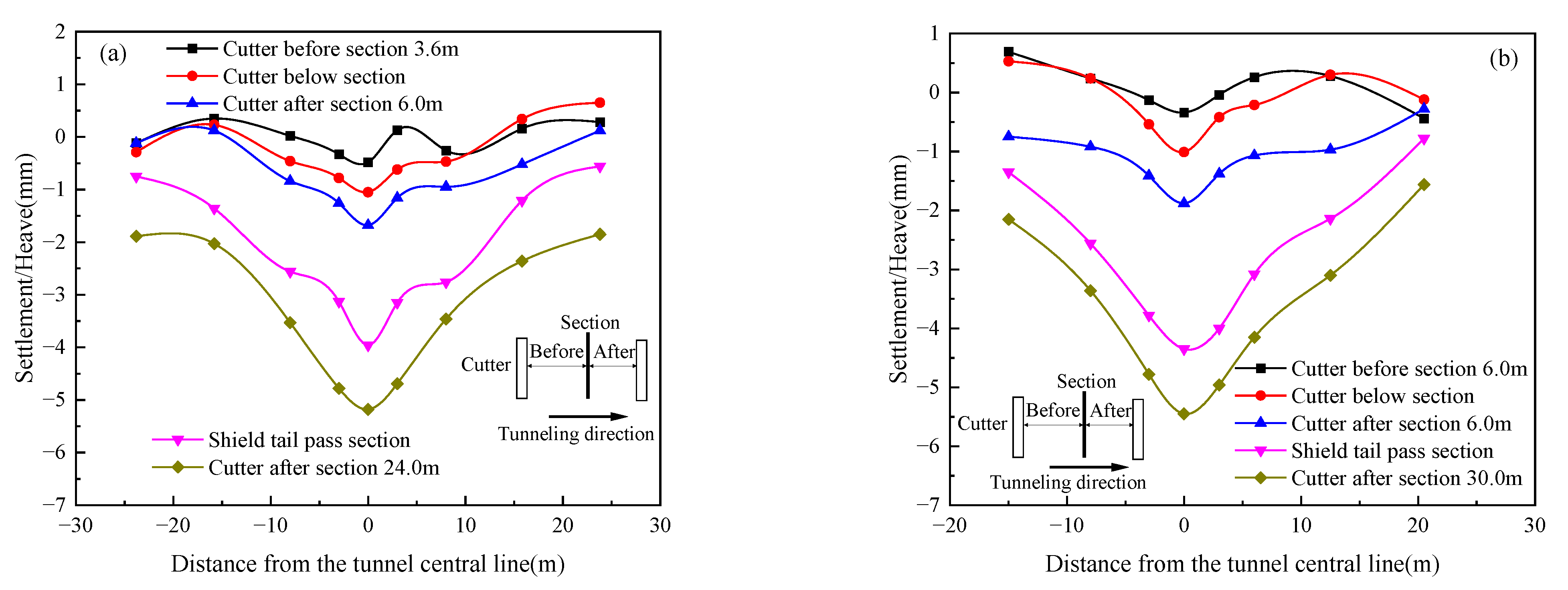
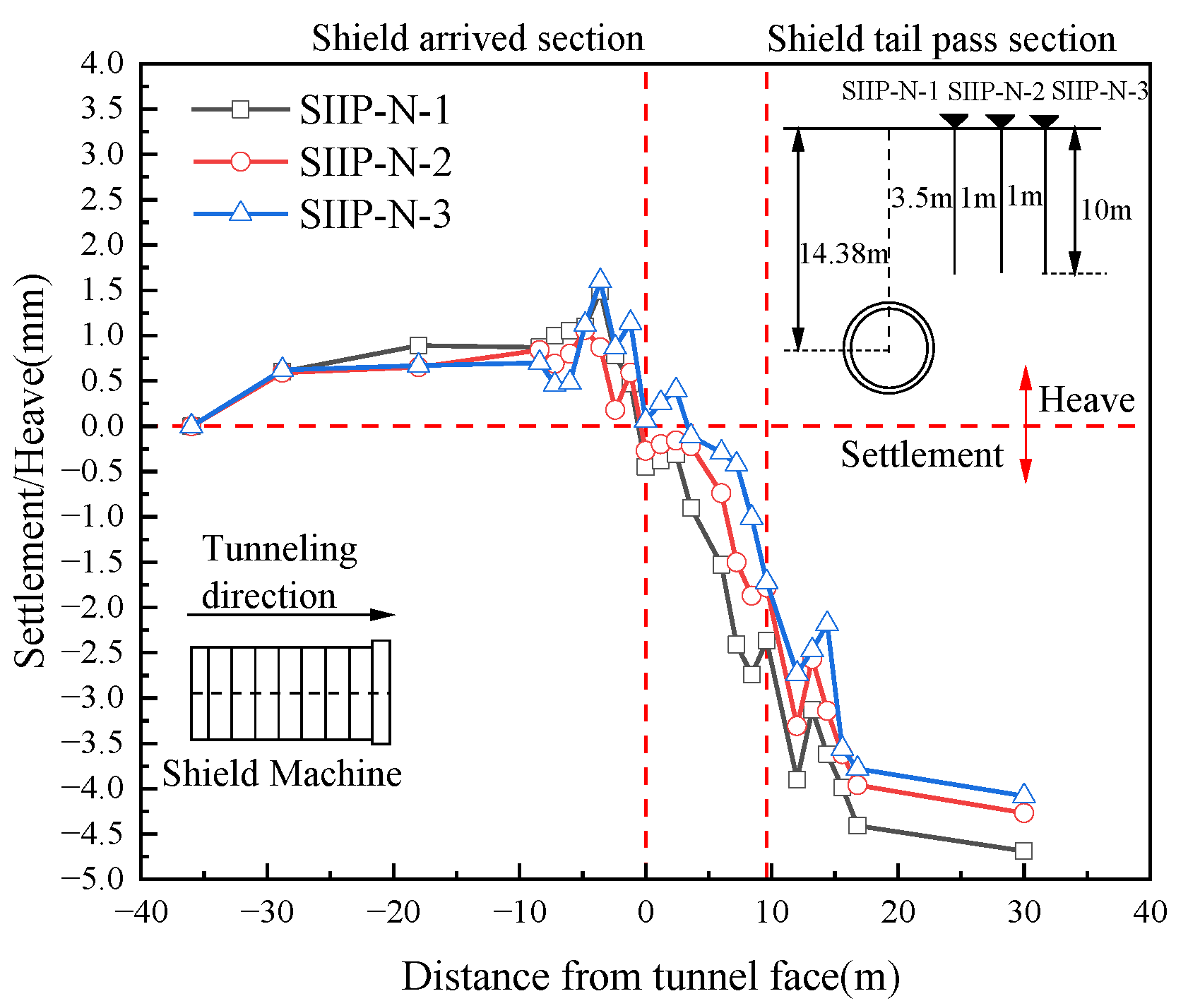
3.1. Surface Settlement Analysis

Surface settlement is one of the most important indicators to measure the safety of shield tunneling. If the settlement exceeds the allowable value of field monitoring, it will cause pavement collapse, endanger the safe use of surrounding buildings, and even cause engineering accidents.
The specific layout of field monitoring of the surface section of the south line is shown in Figure 3a. The surface cumulative deformation curve of section A is shown in Figure 5. The data are obtained from the cumulative deformation values of section measuring points in the daily monitoring report. The positive value represents the surface heave and the negative value represents the surface settlement. The results show that due to the comprehensive influence of thrust force, grouting pressure, shield tail void, and other factors, the surface deformation of the section experienced the changing trend of the first heave and then settlement, which is distributed in the Gauss curve. During the period of the cutter passing through the section, it is affected by grouting at the shield tail. As can be seen from Figure 5a, the maximum heave value of the ring 330 section reaches 3.09 mm, which increases by 2.02 mm compared with the deformation before reaching the measuring point. Figure 5b shows that the maximum heave value of the ring 350 section is 4.11 mm, which increases by 2.27 mm compared with the deformation before reaching the measuring point. The shield tail prolapse produces voids so that the overlying soil moves downward, resulting in large settlements on both sections. After the cutter passes far away from the monitoring section, the settlement increases further with the dissipation of excess pore water pressure, consolidation, and compression of soil. The final settlement of the ring 330 section is −2.21 mm, and that of the ring 350 section is −1.96 mm.
The specific layout of the surface section of the north line is shown in Figure 3b. The cumulative surface deformation curve of section B is shown in Figure 6. The results show that during shield tunneling, the surface section experiences a continuous settlement process. The surface deformation is relatively gentle before the cutter reaches the front of the section, and the curve law conforms to the Peck settlement curve. Comparing Figure 6a with Figure 6b, the maximum settlement of the ring 350 ring is −1.68 mm and that of the ring 370 section is −1.88 mm during the crossing section. After the shield tail passed through the section, the soil collapsed into the gap at the shield tail, and the two sections caused large settlements of −3.96 mm and −4.35 mm, respectively. After the cutter passes far away from the section, the settlement is further increased due to soil consolidation and compression. The final settlement of the ring 350 section is −5.18 mm and the ring 370 section is −5.45 mm.
From the above analysis, it can be seen that the settlement caused by different shield tunneling stages differs. Table 2 and Table 3 calculate the proportion of surface deformation caused by each shield tunneling stage of the double line.
In the stage of the shield tail passing section, the section deformation of rings 330 and 350 on the south line accounted for 57% and 42% of the total deformation, respectively. The section deformation of rings 350 and 370 on the north line accounted for 44% and 46% of the total deformation, respectively. The surface deformation of the double line is close to 50% of the total deformation. The above data show that the surface settlement is the largest at the stage of the shield tail passing through the section.
This conclusion is consistent with the key stage of settlement formation summarized [16,17]. The grouting stage after the shield tail passes through the section needs to be considered for surface settlement.

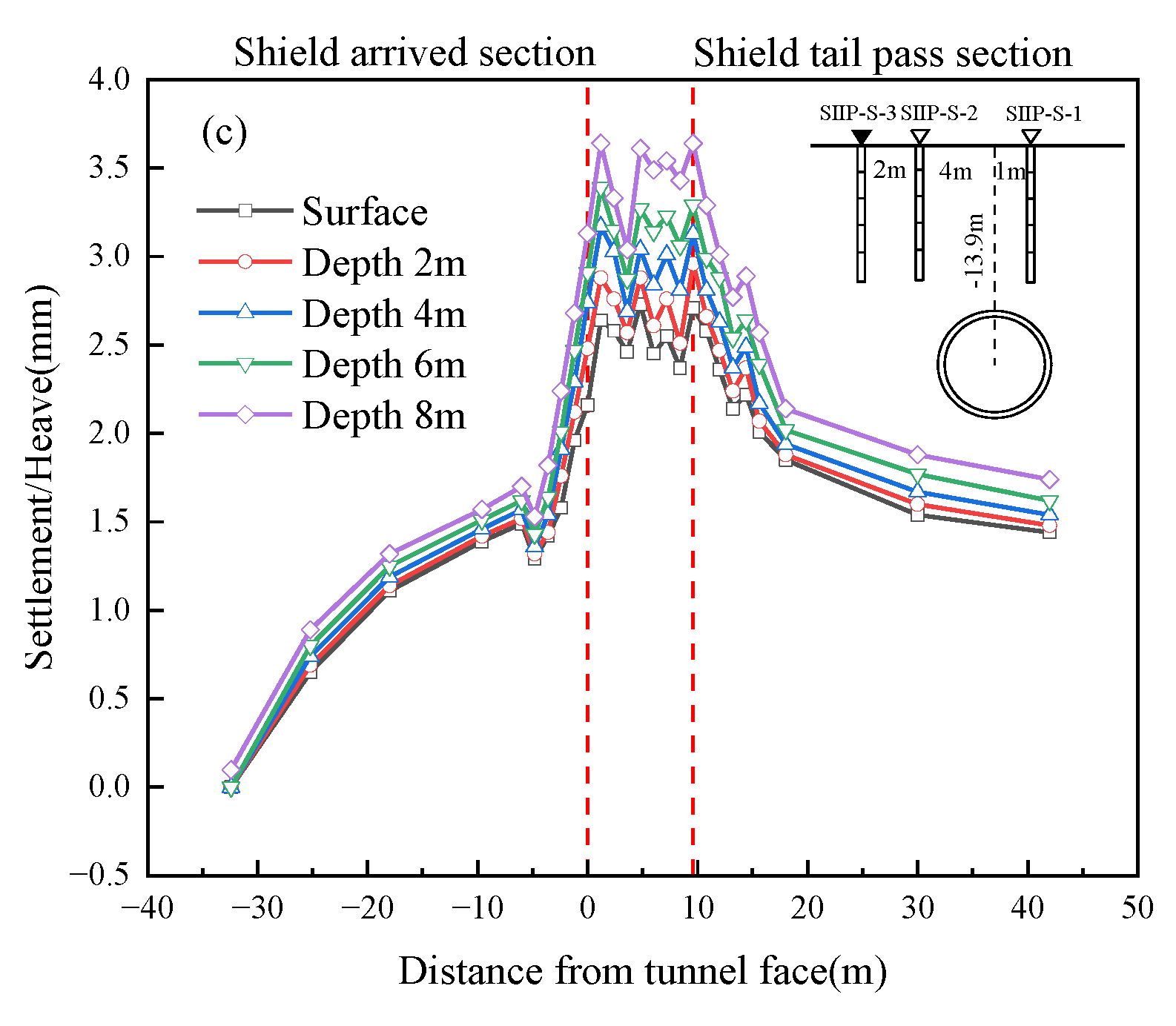
3.2. Analysis of Vertical Displacement of Stratum

Figure 7 is the time history curve of the surface vertical displacement of monitoring section A. The horizontal axis represents the distance between the cutter head and the monitoring section. A positive value indicates that the cutter has passed through the section, whereas a negative value indicates that the cutter has not reached the section. The vertical axis represents the vertical displacement of the ground surface. A positive value is the ground heave, whereas a negative value is the ground settlement.
The surface vertical displacement experienced the following four stages during shield tunneling: (1) When the cutter moves gradually close to section A, the vertical displacement of the surface gradually rises (0–3.2 mm) under the joint action of thrust force and chamber earth pressure. When the cutter reaches the section, the heave is close to the maximum. (2) When the cutter passes through section A, the soil above the shield machine is no longer affected by thrust force and chamber earth pressure. Due to the combined influence of shield posture, shield tail void, and grouting pressure, settlement occurs in the monitoring section. With the excessive grouting pressure, the section soil heaves again. The grouting pressure not only affects the vertical displacement of the soil behind the shield tail but also penetrates into the soil in front of the shield tail, resulting in a change in the vertical displacement of the soil. (3) When the shield tail passes section A, the existence of the gap at the shield tail will theoretically produce soil settlement. However, due to the influence of grouting, and a large grouting pressure (0.249 MPa) is applied at this time, the soil continues to rise by about 0.1 mm compared with the previous stage. (4) When the shield tail is far away from section A, the soil deformation of the section is no longer within the radiation range of the grouting effect, and with the dissipation of pore water pressure, the soil still has a consolidation settlement of about 0.6 mm.
Figure 8 shows the vertical displacement of stratum soil in monitoring section A. The field monitoring results show that the development law of ground deformation at 2 m, 4 m, 6 m, and 8 m below the surface with the advance of the shield is basically consistent with the ground deformation, and generally experiences the four development stages of time history change described above. The stratum with large deformation is 6 m below the surface (located in the middle and lower part of the silt–silty clay layer) and 8 m below the surface (at the bottom of the silt–silty clay layer). In Figure 8a, the cumulative maximum heave at 6 m below the surface is 4.21 mm, and the cumulative maximum heave at 8 m below the surface is 4.47 mm. In Figure 8b, the cumulative maximum heave at 6 m below the surface is 3.81 mm, and the cumulative maximum heave at 8 m below the surface is 4.09 mm. In Figure 8c, the cumulative maximum heave at 6 m below the surface is 3.29 mm, and the cumulative maximum heave at 8 m below the surface is 3.64 mm.
In summary, major increments in heave deformation values occur in the stage before the shield cutter reaches the monitoring section. Due to the extrusion disturbance of shield tunneling on the front soil, the heave deformation of soil increases. When the shield crosses the monitoring section, the shield tail grouting has a great impact on the soil deformation value of the section. Under the joint action of grouting pressure and grouting volume, the shield tail passing the section reaches the maximum value.
Figure 9 is the time history curve of the surface vertical displacement of monitoring section B. As shown in Figure 9, the surface vertical displacement experiences the following five stages during tunneling: (1) When the cutter head is far away from section B, the vertical displacement of the ground surface hardly changes. (2) When the cutter approaches section B, under the joint action of thrust force and chamber earth pressure, the soil in front of the shield is extruded and deformed. The surface begins to rise, and the amount of heave increases gradually (about 0–1.5 mm). (3) When the cutter passes through section B, the soil layer above the shield machine is no longer affected by thrust force and the chamber earth pressure. Due to the influence of shield posture and the existence of shield tail clearance, the monitoring section has a settlement. As the shield moves forward, the section soil layer rises again due to the excessive grouting pressure at the tail of the shield. This phenomenon shows that the grouting pressure not only affects the vertical displacement of the soil behind the shield tail but also penetrates into the soil in front of the shield tail, resulting in a change in the vertical displacement of the soil in front. (4) When the shield tail is about to pass section B, and due to the existence of a gap at the shield tail and the fact that the shield crossing layer is a round gravel layer, the porosity is large. After the gap is generated, the soil above falls rapidly and causes a large settlement (about 1–1.5 mm). (5) After the shield tail passes through section B, the consolidation settlement (about 0.7 mm) of the surface soil occurs with the gradual dissipation of pore water pressure.
Figure 10 shows the vertical displacement of soil mass on section B. The field monitoring results show that the development law of stratum deformation at 2 m, 4 m, 6 m, 8 m, and 10 m below the surface with the advance of the shield is basically consistent with the surface deformation, and large stratum deformation occurs at 6 m below the surface (located in the middle and lower part of the silt–silty clay layer) and 10 m below the surface (the interface between round gravel layer and silty clay layer, closest to the top of the tunnel). In Figure 10a, the cumulative maximum heave at 6 m below the surface is 1.71 mm and the cumulative maximum settlement is 7.37 mm; the cumulative maximum heave at 10 m below the surface is 2.78 mm and the cumulative maximum settlement is 6.9 mm. In Figure 10b, the cumulative maximum heave at 6 m below the surface is 1.03 mm and the cumulative maximum settlement is 5.51 mm. The cumulative maximum heave at 10 m below the surface is 1.44 mm and the cumulative maximum settlement is 5.34 mm. In Figure 10c, the cumulative maximum heave at 6 m below the surface is 2.57 mm and the cumulative maximum settlement is 6.43 mm. The cumulative maximum heave at 10 m below the surface is 3.85 mm and the cumulative maximum settlement is 6.23 mm. In summary, the maximum heave deformation occurs at the stage before the shield cutter reaches the monitoring section. Due to the extrusion disturbance of shield tunneling on the soil in front, the heave deformation of the soil increases. The maximum settlement is at a long distance after the shield tail passes through the monitoring section. Due to the shield tail passing section, the existence of a gap at the shield tail will produce a corresponding settlement. In addition, the dissipation of excess pore water pressure after crossing leads to consolidation settlement of the soil, which further increases the settlement of the soil.

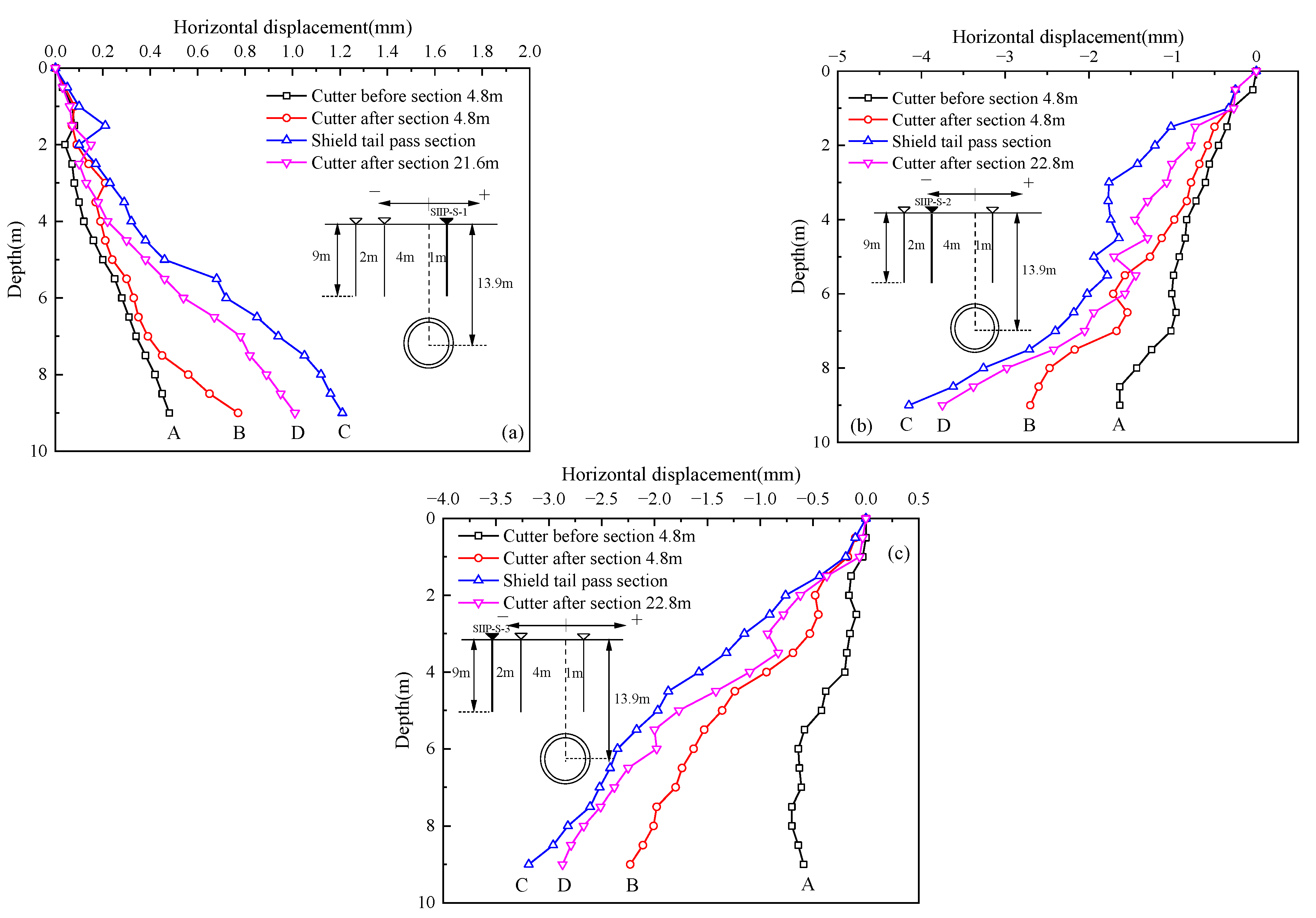
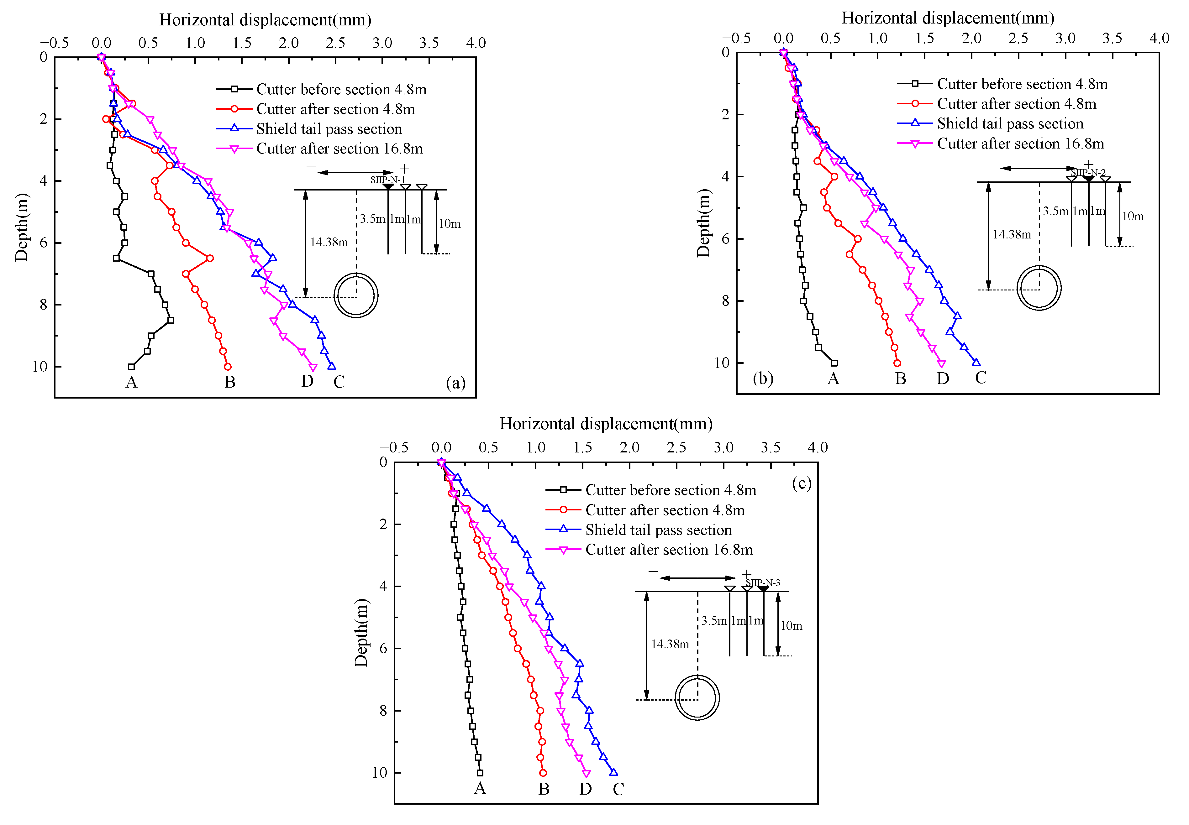
3.3. Analysis of Horizontal Displacement of Stratum

Figure 11 shows the horizontal displacement curve of each measuring point of the monitoring section A at different times. For construction safety purposes, the inclinometer tube at the monitoring point is buried 9 m deep and is not drilled into the bottom of the tunnel. The SIIP-S-1 measuring point is 1 m away from the tunnel axis and is located in the upper part of the tunnel, with little influence on the horizontal displacement. The SIIP-S-2 and SIIP-S-3 measuring points are 4 m and 6 m away from the tunnel axis, respectively, and are located above the tunnel. The horizontal displacement is significantly affected by the tunnel construction. When the shield tail passes through the section, stress release occurs in the soil; however, it is influenced by the grouting pressure, and the outward expansion deformation of the soil continues to increase. The maximum deformation values of SIIP-S-2 and SIIP-S-3 are 4.15 mm and 3.19 mm, respectively. The soil deformation is basically stable when it is far away from the monitoring section. With the dissipation of excess pore water pressure and the curing shrinkage of slurry, the horizontal deformation of soil shrinks and SIIP-S-2 and SIIP-S-3 reach the stable values of 3.75 mm and 2.87 mm. This development pattern is the same as the conclusion of Jiang et al. [18].
Figure 12 is the horizontal displacement curve of each measuring point during the monitoring of section B at different times. The monitoring results show: (1) During shield tunneling, the soil around the tunnel expands and deforms from the point of approaching the measuring point to crossing, and the maximum deformation values of SIIP-N-1, SIIP-N-2, and SIIP-N-3 are 1.35 mm, 1.21 mm and 1.08 mm, respectively. Because the shield shell produces extrusion friction with the surrounding soil during construction, it has an obvious disturbance effect on the soil. After the shield tail passes the section, under the influence of grouting pressure at the shield tail, the outward expansion deformation of the soil continues to increase, and the maximum deformation values of SIIP-N-1, SIIP-N-2, and SIIP-N-3 reach 2.46 mm, 2.05 mm and 1.83 mm, respectively. When far away from the monitoring section, the excess pore water pressure dissipates, the slurry solidifies and shrinks, and the horizontal deformation of the soil shrinks inward. The maximum deformation values of SIIP-N-1, SIIP-N-2, and SIIP-N-3 reach 2.26 mm, 1.68 mm, and 1.54 mm, respectively. (2) The maximum horizontal displacement of the soil at the south line monitoring point is concentrated at 2–4 mm, and the maximum horizontal displacement of the soil at the north line monitoring point is concentrated at 1–3 mm. This is because the grouting pressure of the south line is concentrated at 0.21–0.27 MPa, while the grouting pressure of the north line is concentrated at 0.18–0.22 MPa, which is much smaller than that of the south line. The grouting pressure has a great impact on soil deformation disturbance. (3) As for the south line, in each tunneling stage, the deformation value close to the tunnel monitoring point is greater than the tunnel monitoring point. This shows that the compaction effect of the surrounding soil is obvious during shield tunneling, and with the distance from the monitoring point of the shield, the horizontal displacement gradually decreases and the compaction effect gradually weakens. This conclusion is consistent with Yu et al. [19].

4. Analysis of Shield Tunneling Parameters

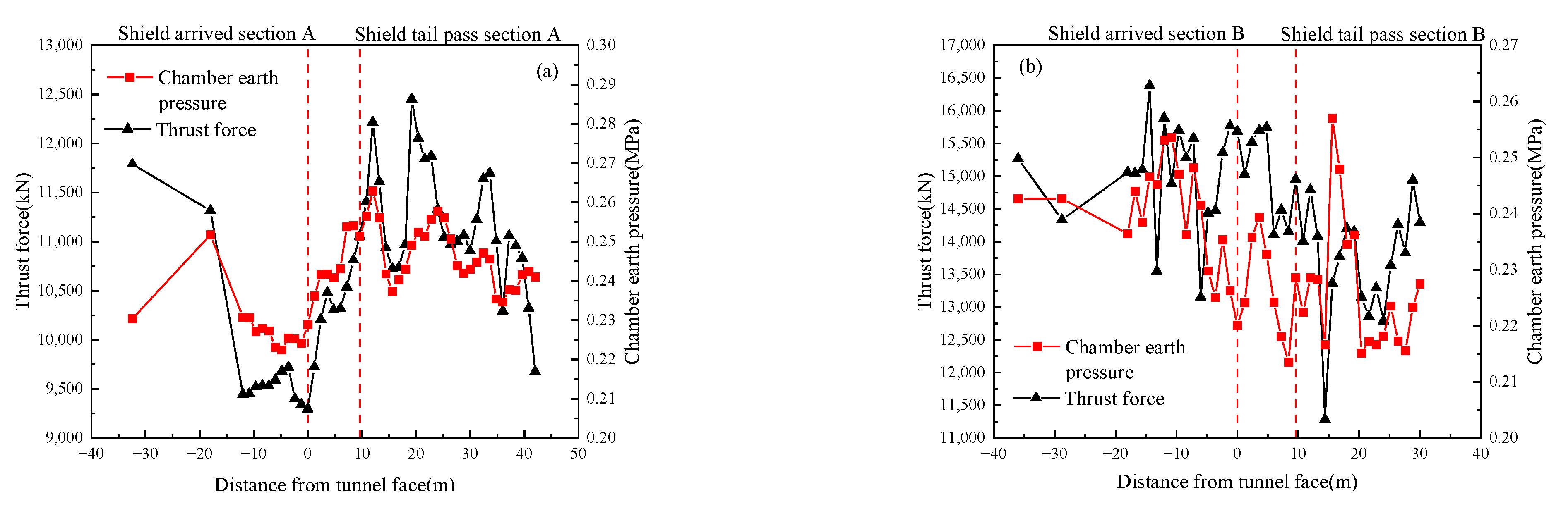
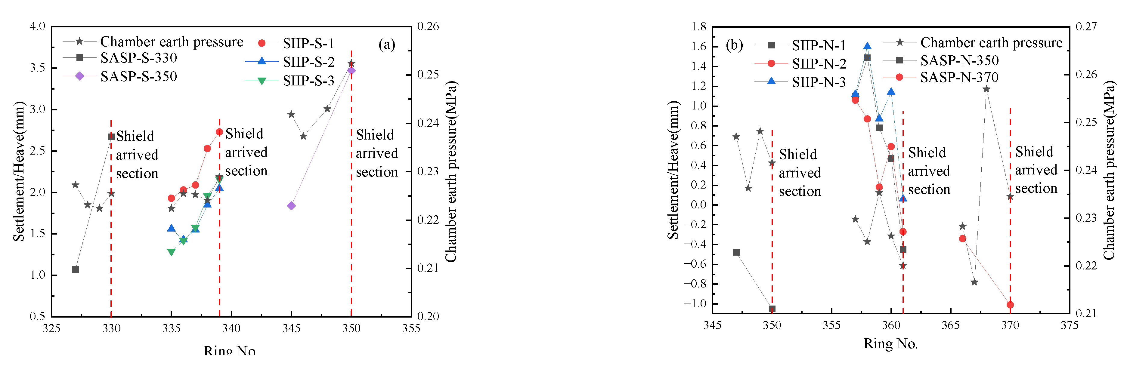
4.1. Chamber Earth Pressure and Thrust Force

In shield tunneling, the shield machine is mainly pushed by the thrust force. The chamber earth pressure reduces the soil deformation in front of the cutter by balancing the earth pressure in front of the cutter. The chamber earth pressure and thrust force in this study are obtained by real-time monitoring of the shield control system. The chamber earth pressure is the average value of each earth tank pressure. Thrust force is the superposition value of each thrust force.
The preset value of the chamber earth pressure refers to the calculation method of static earth pressure and loose earth pressure proposed by Yang et al. [20]. The value range of the static earth pressure and Terzaghi loose earth pressure are 0.24–0.30 MPa and 0.23–0.36 MPa, respectively. As shown in Figure 13, the actual chamber earth pressure of the south line is in the range of 0.22–0.27 MPa, and the north line is in the range of 0.22–0.23 MPa, indicating that the preset chamber earth pressure is reasonable.
At the same time, it is found from the two figures that the thrust force has a good positive correlation with the chamber earth pressure. Figure 13a shows that when crossing section A, the chamber earth pressure and thrust force fluctuate greatly. The chamber earth pressure rises rapidly from 0.23 MPa to 0.25 MPa when the shield tail comes out, increases by 8.7%, and then stabilizes to about 0.24 MPa. To ensure the stability of the soil pressure in front of the cutter, the thrust force needs to be applied synchronously. It rises rapidly from 9296 kN at the crossing section to 11056 kN (an increase of 18.9%) and stabilizes to about 10750 kN after strong fluctuation.
As shown in Figure 13b, the fluctuation of chamber earth pressure and thrust force is relatively small. The chamber earth pressure rises rapidly from 0.220 MPa when crossing the section to 0.229 MPa when the shield tail is disengaged, increases by 4.1%, and then stabilizes to about 0.225 MPa. The thrust force changes synchronously, rapidly decreases from 15,686 kN to 14,952 kN when crossing the section, then decreases by 4.9%, and then basically stabilizes to about 13,750 kN.
From the above analysis, it can be seen that the trends of chamber earth pressure and thrust force of the south line and the north line are different during crossing. Although the geological conditions of sections A and B are similar, the building environment is different. As shown in Figure 1, there are many large buildings near section A of the south line, while there are open spaces around section B of the north line. Therefore, during crossing, the earth pressure in the south line section is significantly released. To ensure the stability of the pressure in front of the cutter, there is a phenomenon of rapid rise.

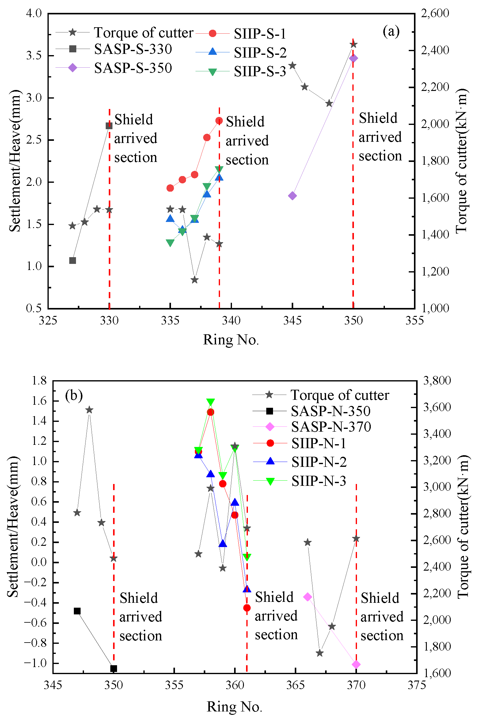
4.2. Torque of Cutter

The torque of the cutter indicates the difficulty of the cutter to cut the soil. Figure 14 shows the cutter torque before and after the shield machine crosses the monitoring section on the south and north lines. It can be seen from the figure that the torque of the cutter on the south line gradually increases when it approaches the monitoring surface, and fluctuates and decreases after the shield tail passing section. The north line fluctuates and declines before the shield tail passing section and rises again after it comes out of the fifth ring road behind the shield tail. The changing trend of torque is basically consistent with the thrust force trend in Figure 13, which is consistent with the conclusion of Xu et al. [13].

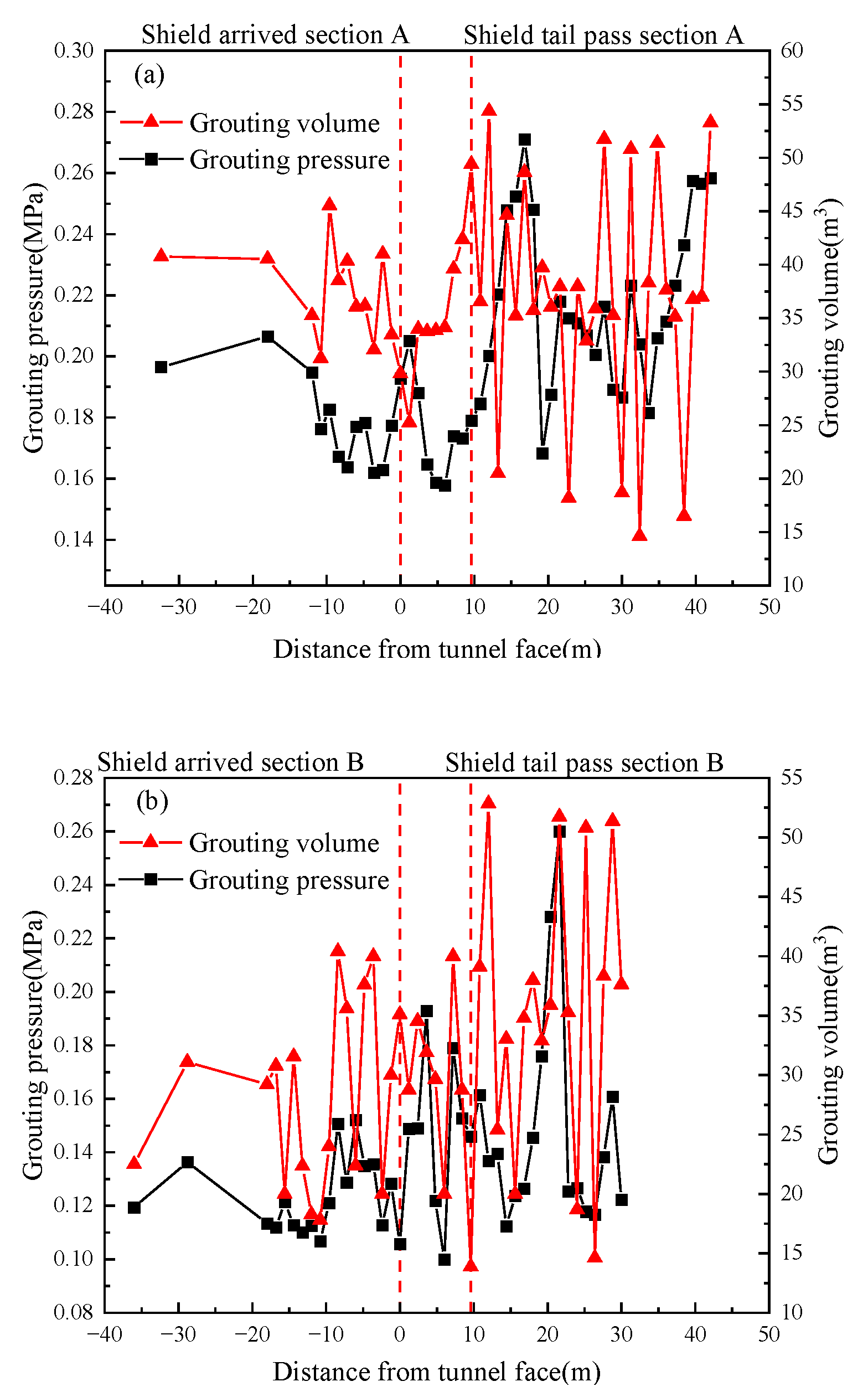
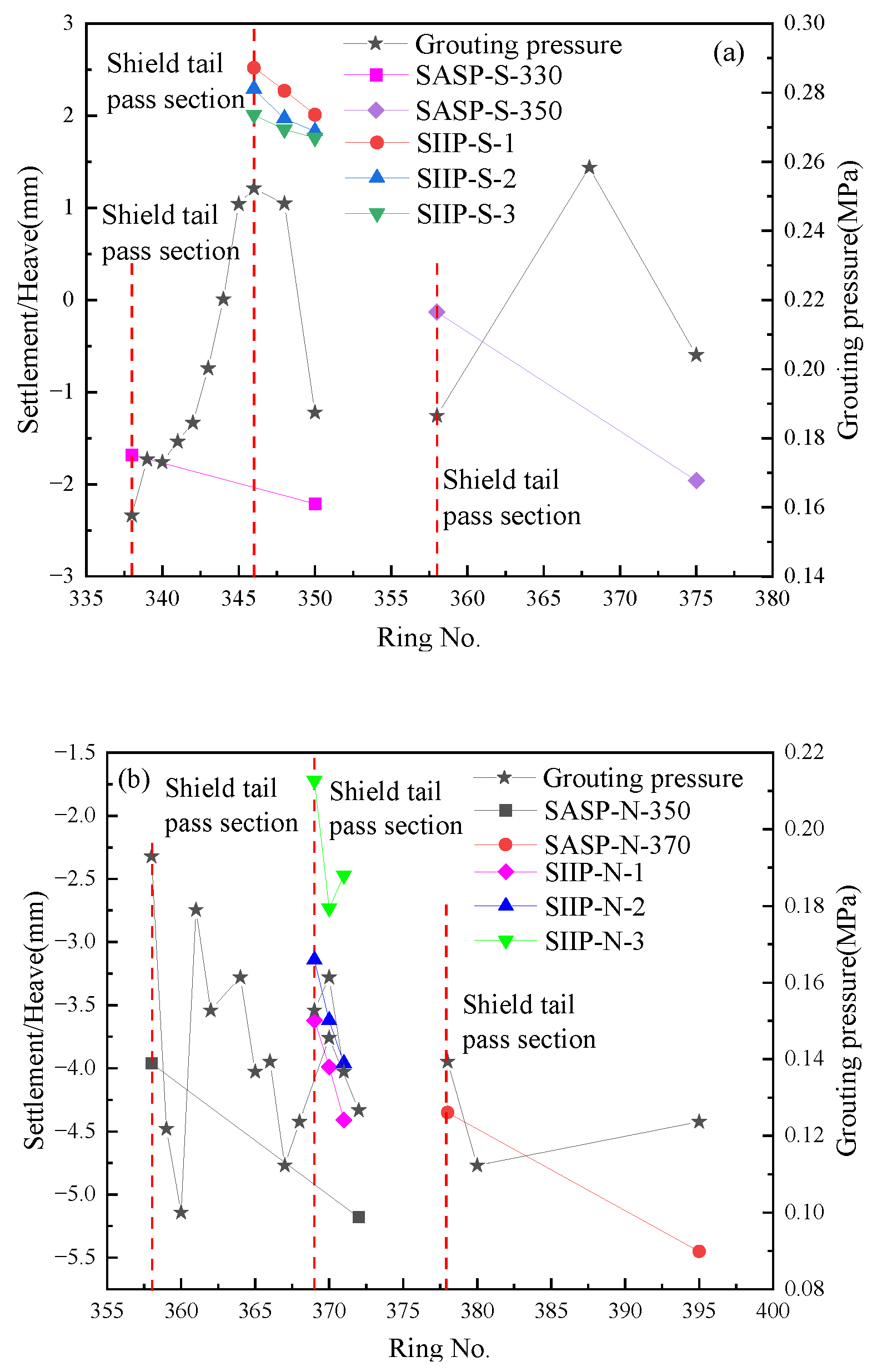
4.3. Grouting Pressure and Grouting Volume

In the process of shield tunneling, ring-shaped gaps are generated between the segment and the soil after the shield tail passing section, which leads to settlement of the soil above. Therefore, grouting is needed to supplement the gap.
Due to the high permeability of the round gravel stratum, the grouting dissipation and slurry loss at the shield tail are more obvious than those in the soft soil layer, which makes the grouting volume and pressure difficult to control. The surface is also prone to a large settlement. As can be seen in Figure 15a, the grouting pressure of the south line is concentrated at 0.16–0.28 MPa, and the grouting amount is 20–53 m3. In the stage of the shield tail pass section, the grouting volume and grouting pressure rise rapidly to varying degrees. This is because the earth pressure acting on the south line is greatly released. After the shield tail passing section, a large amount of grouting pressure and volume are needed right away to supplement the gap at the shield tail. Therefore, the grouting volume and pressure fluctuate greatly after the shield tail passing section.
There is only vacant land above section B of the north line, so the earth stress released and the stratum are relatively small. As shown in Figure 15b, the grouting pressure of the north line is concentrated at 0.11–0.23 MPa, and the grouting volume is concentrated at 20–38 m3, which is significantly smaller than that of the south line. The fluctuation degree is relatively small as well.

5. Discussion

Shield tunneling in round gravel stratum has significant requirements of parameter control, such as chamber earth pressure, thrust force, torque of cutter, grouting pressure, and grouting volume. This study analyses these parameters to explore the size and law of the influence of tunneling parameters on the vertical deformation of the stratum in the round gravel stratum, which has a certain guiding and reference function for the actual project construction.

5.1. Influence of Chamber Earth Pressure and Thrust Force on Surface Deformation

As described in Section 4.1, the chamber earth pressure and thrust force have a great impact on the surface deformation before the shield arrival section. Lee et al. [21] concluded that through the centrifugal model test, the double diameter of the tunnel excavation surface is the tunneling influence range. Therefore, the values of the chamber earth pressure and thrust force around the first five rings of the cutter are selected to establish a relationship diagram with the corresponding surface deformation, as shown in Figure 16 and Figure 17.
As shown in Figure 16a, before the cutter reaches the monitoring section, the surface deformation shows an increasing trend, and the thrust force also shows an increasing trend. When the ring number is 335–339, it increases first and then decreases. This is because the proportion of highly weathered argillaceous siltstone increases, the proportion of round gravel stratum decreases, the friction between soil and shield shell decreases, and the soil still heaves. To ensure small surface deformation, the thrust force needs to reduce. In Figure 16b, ground settlement is observed before the shield cutter reaching the monitoring section, and the thrust force tends to increase to maintain small surface deformation. The thrust force of the north line is significantly greater than that of the south line, and the surface deformation is in the state of settlement. Combined with the analysis of crossing stratum, it is found that the proportion of other strata with natural unit weight greater than round gravel stratum in the south line is less than that in the north line, so the static earth pressure of soil in the north line is greater, and the thrust force required for propulsion is also greater.
As shown in Figure 17a, when the cutter reaches the monitoring section, the surface is heaved, and the chamber earth pressure shows an increasing trend, which is in line with the basic law of chamber earth pressure and surface deformation. In Figure 17b, the surface deformation tends to decrease, but the chamber earth pressure fluctuates. This is because the change in chamber earth pressure has a greater impact on the surface deformation than the thrust force. At the same time, the geological situation of the crossing section is highly complex. To ensure small surface deformation, the chamber earth pressure needs to be continuously adjusted. Therefore, the fluctuation of chamber earth pressure on the north line is greater than that on the south line.
In soft soil areas, the relationship between the thrust force, chamber earth pressure, and surface deformation is similar to that of rounded gravel strata, both being positively correlated [9,22].

5.2. Influence of Torque of Cutter on Surface Deformation

Due to the high correlation between the torque of the cutter and thrust force, the law of the cutter torque and ground deformation is similar to that of thrust force. As shown in Figure 18a, the torque of the cutter is positively correlated with the surface deformation, and there is a significant downward trend in rings 336–337 and 345–347 because of the increasing proportion of fully weathered argillaceous siltstone in the crossing section. In Figure 18b, the torque of the cutter fluctuates and the surface is a settlement. The reason is related to the complexity of crossing the stratum.
The torque of the cutter also has a high correlation with the thrust force in the soft soil area [23]. Therefore, the relationship between cutter torque and surface deformation is also positively correlated, which is consistent with the case of round gravel strata.

5.3. Effects of Grouting Pressure and Grouting Volume on Surface Deformation

The grouting is controlled by the grouting pressure and grouting volume. Bezuijen et al. [24] concluded based on monitoring data that the influence of shield tail grouting is mainly concentrated in the 2–3 rings of the shield tail. Therefore, the extracted shield tail grouting pressure, grouting volume, and the corresponding surface deformation are plotted in Figure 19 and Figure 20.
As shown in Figure 19a, after the shield tail passing section, the grouting pressure increases first and then decreases, and the surface tends to settle. This is because the grouting pressure increases rapidly after the shield tail passing section so that a large amount of slurry replenishes the ring-shaped gap. When the void is filled, the grouting pressure needs to be reduced, otherwise, it will cause surface heave. However, although the grouting pressure fluctuates in Figure 19b, the overall grouting pressure is lower than that of the south line. Therefore, the surface deformation of the northern line shows a settlement trend.
As shown in Figure 20a, after the shield tail passing section, the grouting amount increases first and then decreases, but the surface shows a tendency toward continuous settlement. This is because the grouting volume increases rapidly after the shield tail passing section so that a large amount of grout replenishes the ring-shaped gap. When the gap is filled, over-injection should not be carried out, otherwise, it will cause the surface to heave. In Figure 20b, although the grouting pressure fluctuates, the overall grouting volume is smaller than that of the south line. Therefore, the surface deformation of the north line shows a settlement trend. After ring 356, the surface settlement values all exceed 1 mm or even reach 1.5 mm. This is because the proportion of fully weathered argillaceous siltstone and medium weather argillaceous siltstone after ring 356 decreases, while the porosity of the round gravel stratum increases after being disturbed. As a result, the overall void ratio of soil in the crossing section increases, the leakage of slurry increases, and the surface settlement increases.
In similar projects in soft soil areas, the influence of grouting volume and grouting pressure on surface deformation is similar to that of round gravel stratum. However, the values of grouting volume and grouting pressure are relatively smaller [14,22]. This is because the low void ratio and high water content of the soft soil prevents the grouting slurry from penetrating and spreading [23]. Therefore, the effect of grouting pressure and grouting volume on surface deformation in round gravel stratum is different from that in soft soil. This phenomenon should be emphasized.

5.4. Discussion on Vertical Displacement Anomaly of Stratum in North Line

The stratum deformation is affected by the soil properties, which mainly include soil unit weight, compressive modulus, and other factors. There is an abnormal phenomenon in Figure 10, that is, the vertical displacement at 6 m from the ground surface is the maximum. The vertical displacement at 8 m and 10 m depths are relatively close to the shield tunnel and with large disturbance.
There are two reasons for this phenomenon. The first is that in the synchronous grouting stage, the continuous application of grouting pressure after the shield tail gap filled with grouting slurry will increase the surrounding soil displacement. In the meantime, the transmission of grouting pressure offsets the excavation unloading stress at a certain depth, reducing the vertical displacement at this depth (Figure 21). The blue line indicates the stratum settlement caused by shield tunneling at this depth, the red line indicates the stratum heave caused by grouting at this depth, and the overlapping part is the final settlement value of the stratum.
The second reason is that the monitored soil stratum is muddy silty clay with a compressive modulus of 2.3 MPa, which is smaller than the compressive modulus of the next layer of silty clay (5.5 MPa) and is easily deformed by external disturbances.
As the thickness of the silty clay layer with heavy overlying soil is small (silty clay layer is 1.8 m thick, muddy silty clay layer is 6.3 m thick), the vertical displacement is caused by the nature of the stratum and the tunneling environment is relatively limited. Ultimately, the vertical displacement of the stratum at a depth of 6 m is greater than that at a depth of 8 m and 10 m.

6. Conclusions

This study took the shield tunneling construction of the round gravel stratum in the access section of Hangzhou Metro Line 3 as the background and relied on field monitoring data of the test section. In the monitoring area, the variation law between the tunneling parameters such as chamber earth pressure, thrust force, the torque of the cutter, grouting volume and grouting pressure and the deformation of the surface section, vertical displacement, and horizontal displacement of the stratum during the shield tunneling process were analyzed. The main conclusions are summarized as follows:
(1)
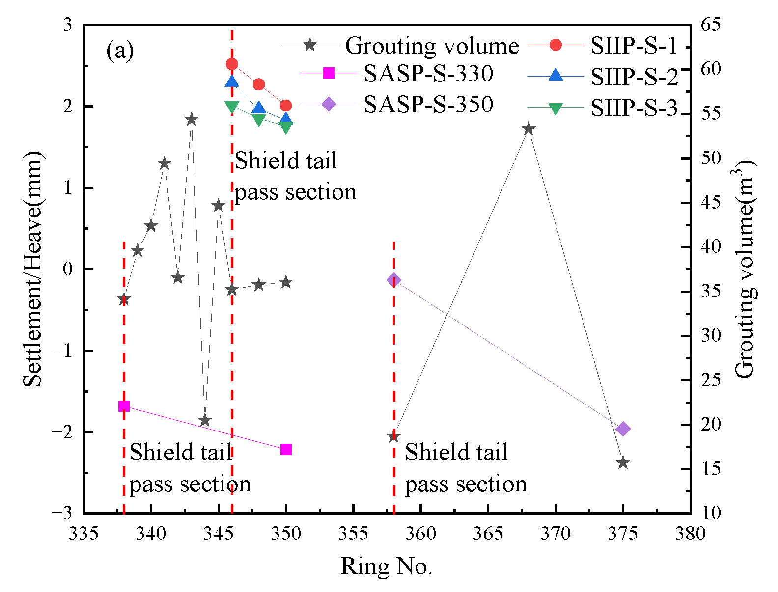
When the EPB shield passes through the round gravel stratum, the chamber earth pressure, thrust force, torque of the cutter, grouting pressure, and grouting volume are all positively correlated with the surface. Before the shield arrives at the section, the influence of chamber earth pressure, thrust force, and torque of the cutter on the surface deformation are mainly affected by the change in the stratum soil pressure in the tunneling stage, and the chamber earth pressure is the tunneling parameter that affects the surface deformation the most.
In the stage of the shield tail passing section, the grouting volume and grouting pressure on the surface deformation are mainly affected by the change in the void ratio of the stratum, and the grouting volume is the tunneling parameter that has the greatest influence on the surface deformation.
(2)
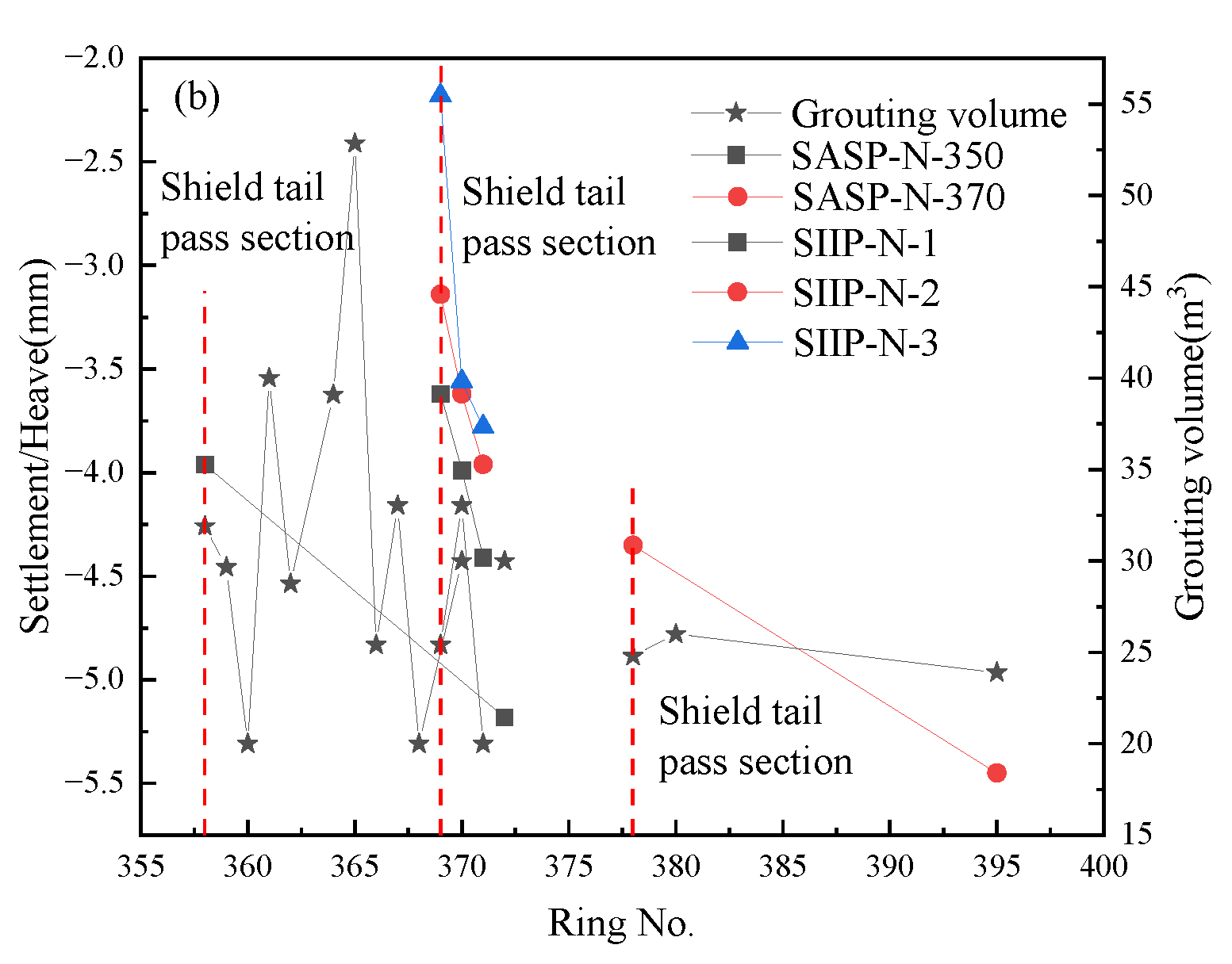
During the process of the EPB shield passing through the round gravel stratum, the deformation curve of the surface corresponds to the Gauss curve, and the curve law conforms to the settlement form of the Peck formula. The heave value of the southern line reaches the maximum during the crossing stage, and the northern line reaches the maximum when it approaches the monitoring surface.
(3)
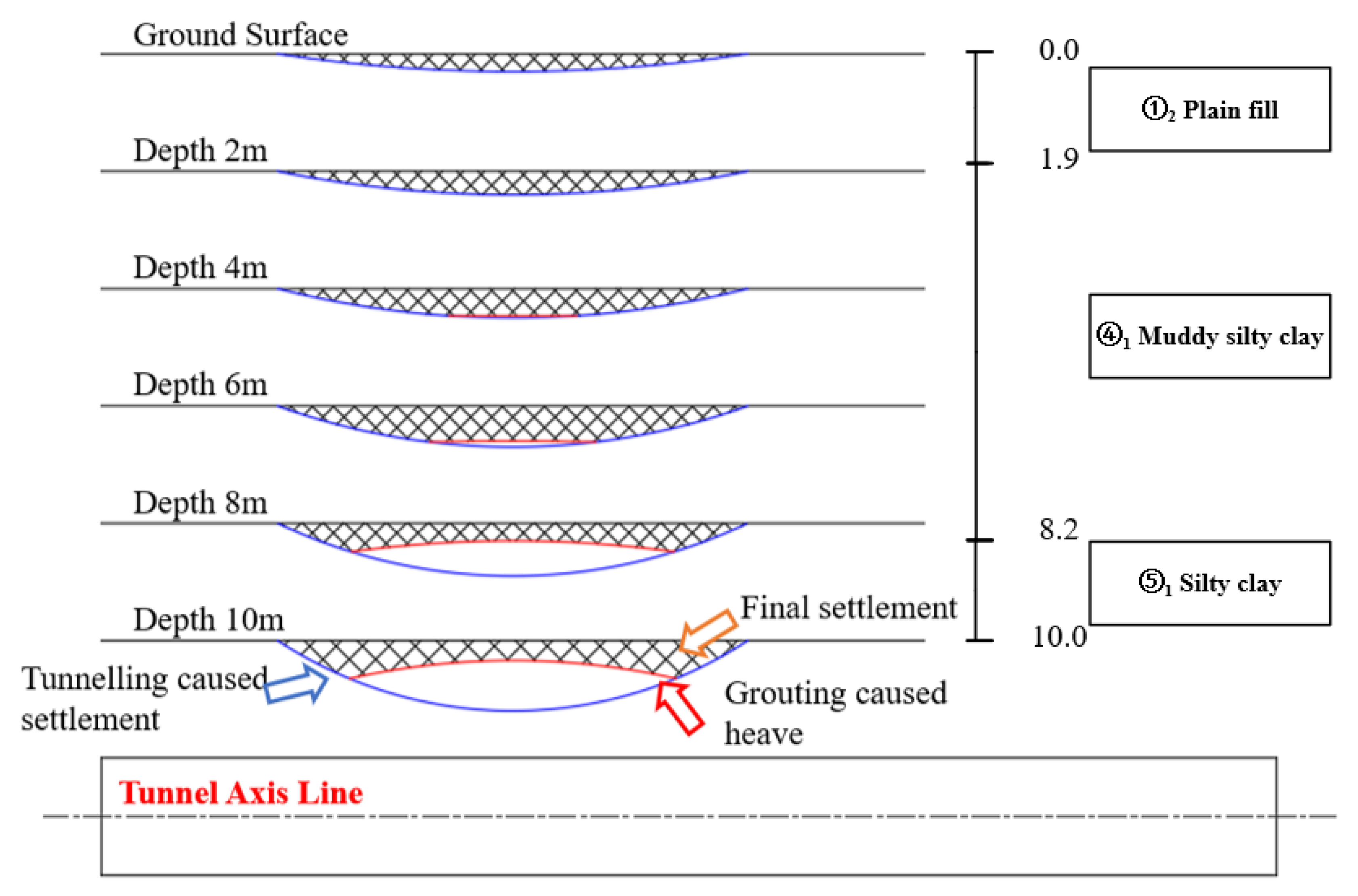
The stratum around the southern line was heaved before the shield arriving section, fluctuated during the crossing stage, decreased after the shield tail pass section, and finally stabilized. The closer it is to the tunnel, the greater the degree of disturbance and the greater the change in the vertical displacement of the ground surface. The stratum displacement of the north line is weak before the shield arriving section reaches the heave degree, and it is in a settlement state during the crossing stage and after the shield tail passing section. Combining the three aspects of soil layer thickness, soil compressive modulus, earth stress release, and grouting pressure offset, the problem that the settlement value at the depth of 6 m is greater than that at the depth of 8 m and 10 m is explained.
(4)
The horizontal displacement of the soil increases along with the depth fluctuation and the maximum value is observed at a depth of 10 m. In the tunneling stage, the minimum value occurs when the shield does not reach the monitoring section, and the maximum value is reached when the shield tail passes the section. The closer to the tunnel axis, the greater the horizontal displacement along with the depth.

Author Contributions

Conceptualization, methodology, supervision, Z.W., J.S. and S.X.; data curation, formal analysis, S.W., W.F. and P.W.; investigation, original draft preparation, formal analysis, W.F. and S.W.; writing—review and editing, W.F. and Z.Y.; project administration, Z.Y. and J.S. All authors have read and agreed to the published version of the manuscript.

Funding

This research received no external funding.

Institutional Review Board Statement

Not applicable.

Informed Consent Statement

Not applicable.

Data Availability Statement

Not applicable.

Conflicts of Interest

The authors declare no conflict of interest.

References

  1. Wen, J.Y. EPBS Tunnel Construction in Soft Soil and Fractured Formation: A Case Study of LanZhou Subway Line 1. American Society of Civil Engineers. In Proceedings of the International Conference on Pipelines and Trenchless Technology 2014, Xiamen, China, 13–15 November 2014; pp. 780–790. [Google Scholar] [CrossRef]
  2. Zhu, H.H.; Xu, Q.W.; Zheng, Q.Z.; Liao, S.M. Experimental study on the working parameters of EPB shield tunneling in soft ground. China Civ. Eng. J. 2007, 9, 87–94. (In Chinese) [Google Scholar]
  3. Farmer, P.B.; Attewell, I.W. Ground Deformations Resulting from Shield Tunnelling in London Clay. Can. Geotech. J. 1974, 11, 380–395. [Google Scholar] [CrossRef]
  4. Deane, A.P. The Heathrow express trial tunnel. Int. J. Rock Mech. Min. Sci. Geomech. Abstr. 1995, 32, 411A. [Google Scholar] [CrossRef]
  5. Van der Berg, J.P.; Clayton, C.R.I.; Powell, D.B. Displacements ahead of an advancing NATM tunnel in the London clay. Géotechnique 2003, 53, 767–784. [Google Scholar] [CrossRef]
  6. Clayton, C.R.I.; Van Der Berg, J.P.; Thomas, A.H. Monitoring and displacements at Heathrow Express Terminal 4 station tunnels. Géotechnique 2006, 56, 323–334. [Google Scholar] [CrossRef]
  7. Standing, J.; Selemetas, D. Greenfield ground response to EPBM tunnelling in London Clay. Geotechnique 2013, 63, 989–1007. [Google Scholar] [CrossRef]
  8. Wan, M.S.P.; Standing, J.R.; Potts, D.M.; Burland, J.B. Measured short-term subsurface ground displacements from EPBM tunnelling in London Clay. Géotechnique 2017, 67, 748–779. [Google Scholar] [CrossRef]
  9. Lee, K.M.; Ji, H.W.; Shen, C.K.; Liu, J.H.; Bai, T.H. Ground response to the construction of Shanghai metro tunnel-line 2. Soils Found. 1999, 39, 113–134. [Google Scholar] [CrossRef] [Green Version]
  10. Xu, Q.W.; Zhu, H.H.; Ding, W.Q.; Ge, X.R. Laboratory model tests and field investigations of EPB shield machine tunnelling in soft ground in Shanghai. Tunn. Undergr. Space Technol. 2011, 26, 1–14. [Google Scholar] [CrossRef]
  11. Xie, X.; Yang, Y.; Ji, M. Analysis of ground surface settlement induced by the construction of a large-diameter shield-driven tunnel in Shanghai, China. Tunn. Undergr. Space Technol. Inc. Trenchless Technol. Res. 2016, 51, 120–132. [Google Scholar] [CrossRef]
  12. Zhu, Y.H.; Gao, F.; Ye, J.N.; Bian, X.C.; Lin, W.A.; Chen, Y.M. Lateral Ground Displacement Induced by EPB Tunneling in Ningbo Soft Clay. In Proceedings of the International Symposium on Environmental Vibration and Transportation Geodynamics, Hangzhou, China, 28–30 October 2016; Springer: Singapore, 2016. [Google Scholar] [CrossRef]
  13. He, C.; Feng, K.; Fang, Y.; Jiang, Y.V. Surface settlement caused by twin-parallel shield tunnelling in sandy cobble strata. J. Zhejiang Univ. SCIENCE A 2012, 13, 858–869. [Google Scholar] [CrossRef]
  14. Zhang, Z.X.; Zhang, H.; Yan, J.Y. A case study on the behavior of shield tunneling in sandy cobble ground. Environ. Earth Sci. 2013, 69, 1891–1900. [Google Scholar] [CrossRef]
  15. Liu, C.; Cui, J.; Zhang, Z.X.; Liu, H.; Huang, X.; Zhang, C.Q. The role of TBM asymmetric tail-grouting on surface settlement in coarse-grained soils of urban area: Field tests and FEA modelling. Tunn. Undergr. Space Technol. 2021, 111, 103857. [Google Scholar] [CrossRef]
  16. Nomoto, T.; Imamura, S.; Hagiwara, T.; Osamu, K. Shield Tunnel Construction in Centrifuge. J. Geotech. Geoenviron. Eng. 1999, 125, 289–300. [Google Scholar] [CrossRef]
  17. Cheng, H.Z.; Chen, J.; Chen, G.L. Analysis of ground surface settlement induced by a large EPB shield tunnelling: A case study in Beijing, China. Environ. Earth Sci. 2019, 78, 605. [Google Scholar] [CrossRef]
  18. Jiang, X.L.; Cui, Y.; Li, Y.; Zhao, Z.M. Measurement and simulation of ground settlements of Tianjin subway shield tunnel construction. Rock Soil Mech.-Wuhan 2005, 26, 91–95. (In Chinese) [Google Scholar]
  19. Yu, X.F.; Ren, H.; Hu, X.D. Analysis of the Disturbance to Surrounding Soils During Shield Driving for the Hangzhou Metro Line 1 Project. Mod. Tunn. Technol. 2014, 51, 166–173. (In Chinese) [Google Scholar]
  20. Yang, Y.; Tan, Z.S.; Peng, B.; Li, J.P.; Wang, G. Study on optimization boring parameters of earth pressure balance shield in water-soaked round gravel strata. China Civ. Eng. J. 2017, 50, 94–98. (In Chinese) [Google Scholar]
  21. Lee, G.T.K.; Ng, C.W. Effects of advancing open face tunneling on an existing loaded pile. J. Geotech. Geoenviron. Eng. 2005, 131, 193–201. [Google Scholar] [CrossRef]
  22. Zhang, H.; Chen, S.G.; Deng, X.F. Analysis of the effect of shield tunneling parameters on ground settlement. Mod. Tunn. Technol. 2010, 47, 48–53. (In Chinese) [Google Scholar]
  23. Zhou, K.; Tan, H.X.; Liang, X.Q.; Qu, C.Z.; Yang, S.J. Analysis of the effect of shield tunneling parameters on ground settlement in Changsha Metro Line 1. J. Hum. Inst. Eng. 2016, 26, 74–79. (In Chinese) [Google Scholar]
  24. Bezuijen, A.; Talmon, A.M.; Kaalberg, F.J.; Plugge, R. Field measurements of grout pressures during tunnelling of the Sophia Rail Tunnel. Soils Found. 2004, 44, 39–48. [Google Scholar] [CrossRef]
Figure 1. Project Overview.
Applsci 12 10553 g001
Figure 2. Longitudinal geological profile of the interval tunnel.
Applsci 12 10553 g002
Figure 3. Layout map of surface settlement measuring points: (a) south line; (b) north line.
Applsci 12 10553 g003
Figure 4. Profile of soil settlement measuring point: (a) south line; (b) north line.
Applsci 12 10553 g004
Figure 5. Surface section deformation of the south line: (a) SSP-S-330; (b) SSP-S-350.
Applsci 12 10553 g005
Figure 6. Surface section deformation of the north line: (a) SSP-N-350; (b) SSP-N-370.
Applsci 12 10553 g006
Figure 7. Development of surface settlement during tunneling in Section A.
Applsci 12 10553 g007
Figure 8. Vertical displacement of stratum soil in Section A: (a) SIIP-S-1; (b) SIIP-S-2; and (c) SIIP-S-3.
Applsci 12 10553 g008aApplsci 12 10553 g008b
Figure 9. Time history curve of surface vertical displacement of section B.
Applsci 12 10553 g009
Figure 10. Vertical displacement of stratum soil in section B: (a) SIIP-N-1; (b) SIIP-N-2; and (c) SIIP-N-3.
Applsci 12 10553 g010
Figure 11. Horizontal displacement of stratum soil in monitoring section A: (a) SIIP-S-1; (b) SIIP-S-2; and (c) SIIP-S-3.
Applsci 12 10553 g011
Figure 12. Horizontal displacement of stratum soil in monitoring section B: (a) SIIP-N-1; (b) SIIP-N-2; and (c) SIIP-N-3.
Applsci 12 10553 g012
Figure 13. Measured values of thrust force and chamber earth pressure: (a) south line; (b) north line.
Applsci 12 10553 g013
Figure 14. Measured value of torque of cutter: (a) south line; (b) north line.
Applsci 12 10553 g014
Figure 15. The relationship between grouting pressure and grouting volume: (a) south line; (b) north line.
Applsci 12 10553 g015
Figure 16. Relationship between thrust force and surface deformation: (a) south line; (b) north line.
Applsci 12 10553 g016
Figure 17. The relationship between chamber earth pressure and surface deformation: (a) south line; (b) north line.
Applsci 12 10553 g017
Figure 18. Influence of torque of the cutter on surface deformation: (a) south line; (b) north line.
Applsci 12 10553 g018
Figure 19. Relationship between surface deformation and grouting pressure: (a) south line; (b) north line.
Applsci 12 10553 g019
Figure 20. Relationship between surface deformation and grouting volume: (a) south line; (b) north line.
Applsci 12 10553 g020aApplsci 12 10553 g020b
Figure 21. Figure of abnormal vertical displacement of stratum on the south line.
Applsci 12 10553 g021
Table 1. Soil parameters.
Geotechnical
Category
Water
Content
/(%)
Natural Unit Weight (kN/m3)Specific Gravity of Soil ParticleVoid RatioLiquid Limit (%)Plastic Limit (%)Poisson
Ratio
Compression
Modulus
(MPa)
Cohesion
(kN/m2)
Friction
Angle
(°)
2 Plain fill30.918.22.730.93838.723.30.343.21010
2 Silty clay26.719.52.720.73340.124.20.365.54317
1 Muddy silty clay45.4172.731.2873823.10.42.3139
1 Silty clay26.119.52.730.7334024.10.365.54317
4 Round gravel22.520.52.7 --0.2617234
(20)1 Fully weathered argillaceous siltstone21.919.619.60.67440.124.10.2862527
(20)2 Highly weathered argillaceous siltstone20.520.320.3---0.2863515.5
(20)3 Medium weathered argillaceous siltstone22.424.524.5---0.28Incompressible17033
Table 2. Proportion of surface deformation during construction of the south line.
Monitoring SectionStage of Shield Tunneling
Cutter
before
Section
Cutter
below
Section
Crossing
Section
Tail
Pass
Section
Final
Settlement
SSP-S-33013%19%5%57%6%
SSP-S-35018%16%6%42%18%
Table 3. Proportion of surface deformation during construction of the north line.
Monitoring SectionStage of Shield Tunneling
Cutter
before
Section
Cutter
below
Section
Crossing
Section
Tail
Pass
Section
Final
Settlement
SSP-N-3509%11%12%44%24%
SSP-N-3706%12%16%46%20%
Publisher’s Note: MDPI stays neutral with regard to jurisdictional claims in published maps and institutional affiliations.

