Abstract
In recent decades, there has been a growing interest in the design and development of power loss reduction in electric drive systems. To realize the full potential of the Brushless DC motor (BLDCM), the design methodology of an effective intelligent controller is vital. On the other hand, the Landsman converter is used in a bridgeless configuration to enhance the power factor and minimize the power loss of the BLDCM. In addition, BLDCM utilizes the different intelligent controllers that are used to decrease power loss. The performance of the Landsman converter and CSC converter is analyzed concerning various configurations/stages, and the numerical MATLAB 2016a simulation results are discussed to arrive at the suitable intelligent controller for the BLDC motor, and comparison results are presented. The proposed converter is designed and validated using hardware implementation by minimizing power loss. Effectiveness can be tested and valued for the proposed controller for the various intelligent controllers of BLDCM.
1. Introduction
The BLDCM is an electronically switched motor that has no brushes. This type of motor is more effective in generating a sufficient amount of torque. In the BLDC motor, a permanent magnet rotated around an astatic armature can be solved with a wide range of competence and flexibility. In stationary conditions, BLDC motors are considered for their torque holding and smooth operation. The rotor is a moving part with a rotor magnet, and the stator is a stationary part that comprises a winding stator. The stator winding, in conjunction with the rotor’s permanent magnet, provides a nearly uniform air gap flux density. This enables the stator coils to be controlled by a DC constant voltage that changes from one stator coil to the other to develop a waveform of AC voltage. The speed of the brushless motors is determined by the frequency at which the current is supplied. As the brushes are not present, the reduction of mechanical energy loss is achieved due to friction, which improves performance in any condition, and BLDC motors can run at high speeds. In recent years, digital twins have been used to perform digital simulations of motors. Mahcine learning algorithms are used to perform exact performance measures [1,2,3,4]. There is less noise and no sparking during operation. For more precise control, extractable electromagnetic material could be used on the stator. BLDC engines accelerate and decelerate quickly due to small rotor inertia. The performance of the motors is high that delivers a wide range of speed control. No ionizing sparks are coming from the switch, and this also minimizes the electromagnetic interference. The BLDC motors are life-saving, maintenance-free, and more reliable. The motor is cooled by conduction, and no airflow is needed for indoor cooling. A positive output can be provided from an input voltage by using the Landsman converter topology, which consists of a series capacitor, occasionally called an inductor, and a flying capacitor. For low power domestic applications, a universal AC mains bridgeless Landsman Power Factor Correction (PFC) converter based on the motor drive was developed and designed. The Landsman converter is used for regulating an unregulated input power supply. The Landsman converter works with reduced conductive losses in Discontinuous Inductor Current Mode (DICM) and switching voltages used to regulate PFC and DC link voltages.
The Landsman converter is capable of overcoming the limits of the several earlier used converters in BLDCM. Using a small input inducer from the Landsman converter, the external ripple is removed using the input ripple filter. The inductor also dampens the oscillator because of the IGBT module. P, PI controllers are equipped with heavy-performance drives. The mathematical theory includes probability theory, multiassessed logic, and artificial intelligence to model a human way of solving various problems through the use of approximate reasoning, the different data sets and decisions that are taken, and the consideration of fuzzy logic. The Continuous Conduction Mode (CCM), regardless of the variance in the degree of insolation, results in stress reduction on its power device and the part on which the Landsman converter is built. The BLDCM speed is regulated using the variation in the DC link voltages. Without supplementary phase current sensors and related mechanisms regulated for speed control are implemented. Irrespective of the atmospheric variations, the motor will run to pump water at the required speed. The BLDC motors, the specific performance of the water pumping system indicated, were evaluated using simulated software results.
A BLDC motor is used for several low-power appliances like ruggedness, high efficiency, high energy density, sensorless control, intelligent control, torque ripple reduction, and also for its fewer maintenance costs. The transport, medical, consumer electronics, heating and ventilation, industrial, and model engineering sectors. BLDCs are eradicated and electronic commutation is used due to the conspired issues with mechanical commutation like sparking, EMI, and tear and wear on brushes. A Hall Effect sensor is supported by a voltage source inverter for position sensing of the rotor. The study shows how the power quality of the AC mains deteriorates due to fluctuations in voltage caused by phase-controlled AC inputs and electrical devices. Flicker sources and their impact on human safety are also indicated. An overview of EMC standards, IEC 61000-3-2, is also provided. The pulse width modulation is followed by the three-phase switching signals. The nonlinear current from harmonic distortion and AC low power factor, which are indices of power quality in the range of ICE 61000-3-2 [5,6,7].
In the air conditioner, for driving the compressor and fan permanent magnet, BLDC replaces a single-phase induction motor for its low power utilization through DC link capacitor and DBR. BLDC motors are fed with a single-phase AC supply, resulting in a pulsed current. In CCM, Critical or Boundary Conduction Mode (CCM/BCM) and DCM of operations are operated by the design of the energy storage element as a converter inductor or capacitor. Compared to the basic converter topologies like buck-boost converter, buck converter, Cuk converter, boost converter, PWM, a converter with a quadratic DC conversion ratio offers a significantly wider conversion range. The switching and conduction losses are reduced by the PFC based on the bridgeless converter for speed control. An AC-DC single-stage converter is proposed for efficient energy harvesting from low-voltage electromagnetic mesoscale and microscale generators. The boost converter is used for energizing the BLDC. The BLDCM velocity is regulated using a Voltage Source Inverter (VSI). The BLDC motor speed is controlled by electronic commutation, which reduces the switching losses [8,9,10].
The Cuk converter is used for PFC as a cost-effective solution. The modified SEPIC rectifier for bridgeless power factor correction can be extended again for universal input voltage applications. PFC can be performed by a bridgeless Zeta converter powered by the BLDC motor, which controls the voltage and the VSI speed. BLDC motor speed and AC mains power factor correction using the Luo converter and the single voltage sensor. The reactive power produced by the load can be generated or absorbed by the bridgeless power factor correction. The canonical switching converter is modified and results in the Landsman converter. A bridgeless canonical switching converter operates in the DICM of a BLDC motor drive for PFC. The concepts of a two-state, single switch, DC to DC voltage sourced converter, canonical switching converter, and issues involved in the design of the input filter are explained and unified [11,12,13].
The work presented in [14] introduce the magnetic potential superimposed method for a more precise calculation of multiphase permanent magnet motors with a large air gap. If the air gap is small, the computing error can be neglected when the conventional formulas are used to calculate the air gap magnetic field. However, they will result in a great error for the evaluation of the airgap motor’s magnetic field with a large air gap. The magnetic potential superimposed method combines better accuracy than the conventional formula method and takes less time than the Finite Element Method. The discussion on the selection of magnetic material that defines the amount of flux in the airgap is not addressed. In [15], a unified model of multiphase PM motors is proposed. For PM motors with multiple phases and stator windings that are nonoverlapping, numerous feasible ratios of the slot to pole number exist by adjusting the coil span angle or unwound tooth width. To get a pole pair m-phase nonoverlapping motor, the nth space harmonic must exist in the stator MMF, and the nth harmonic winding factor must be large enough to accomplish high torque density. The nonworking harmonics influence critical performance such as the torque ripple, back EMF harmonic content, and iron loss, which is not predicted in the design approach.
The use of powerful magnets in [16] allows for the construction of more effective machines. The variation in which the motor is powered by a separate DC/DC converter and the control signals are obtained from an external magnetic disc has the lowest energy losses [17].
The main contribution of the paper includes a MATLAB/Simulink model and develops an intelligent controller for BLDC motor speed control. The simulation results are compared to the proposed method of optimized intelligent controllers for BLDC motor speed control. The various operating scenarios for BLDC motor under various loading conditions are obtained.
The proposed work of the Landsman converter in the BLDC motor to optimize the power loss and power factor correction is mentioned under Section 2. Section 3 and Section 4 contain the simulation and experimental results discussion of the Landsman converter. Finally, Section 5 contains the conclusion of the work.
2. Landsman Converter-Based Power Loss Reduction in BLDC Motor Drive
The BLDC drive, based on the bridgeless landsman PFC converter, is built for PFC in low-power appliances. The BLDC motor speed can be directly tuned using the utilization of DC bus voltage. Electronic switching of the BLDC motor is used to minimize the switching-related loss in six IGBT inverters, enabling a small switching frequency. The single-phase AC supply to the bridgeless landsman converter. The built-in power factor enhancement of the AC supply is performed by the Landsman converter with a bridgeless PFC configuration designed for DCIM operation. Input inductor current during DCIM operation is discontinuous during the switching period.
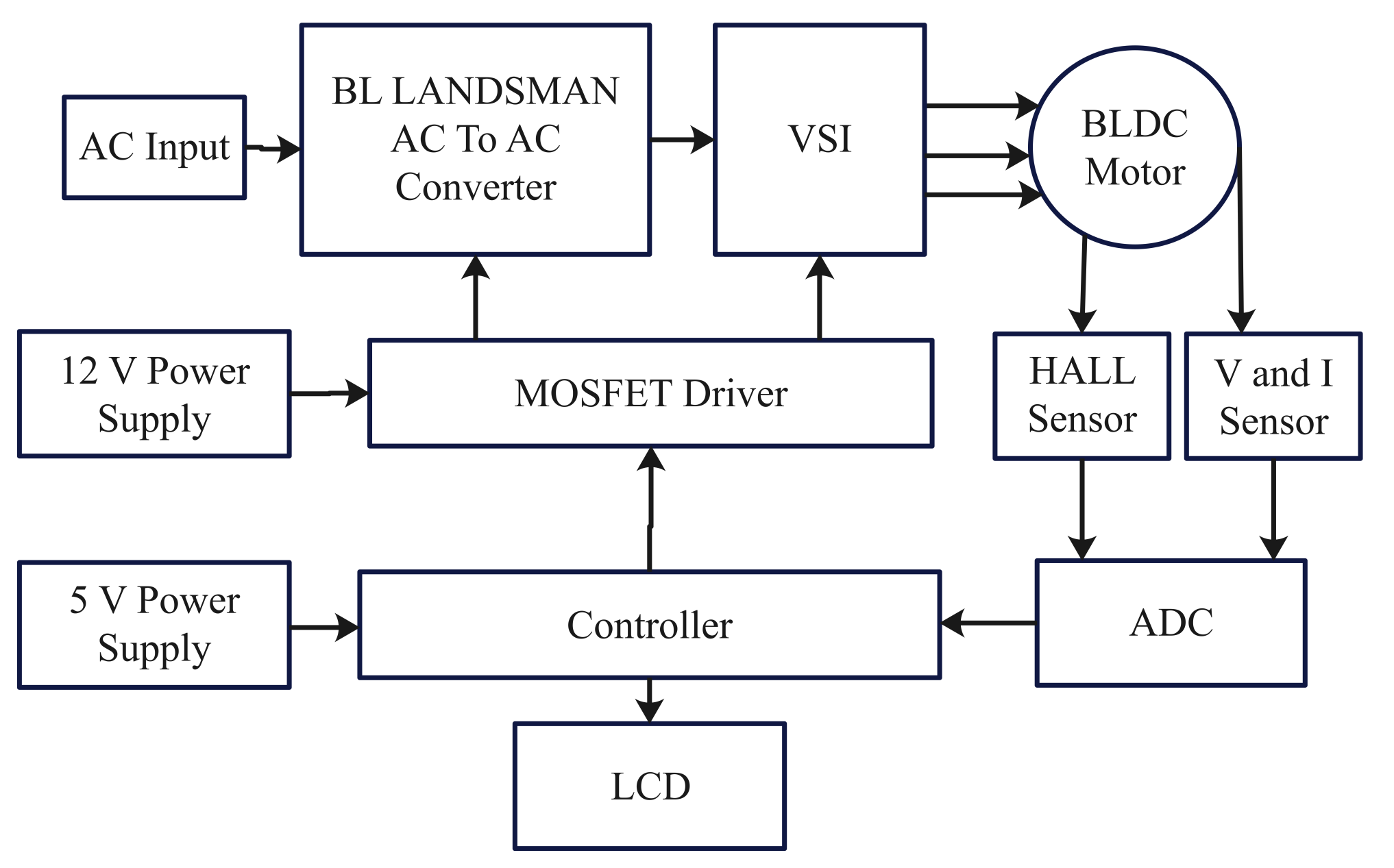
The Landsman converter operates in Modes 1, 2, and 3. Figure 1 shows the Landsman converter-based power loss reduction. In Mode 1, the supply input inductor energy and the energy stored is transferred to the second capacitor as soon as the switch is ON. The secondary capacitor value is available as a continuous voltage during operation. In Mode 2, the output inductor begins to discharge the supply current while the DC link side inductor and the second capacitor are charged during this operation as soon as the switch is OFF. In Mode 3, the converter operates in DCM, where the input inductor is fully discharged and the input current is zero. The voltage of the second capacitor is continuously reducing and the DC bus side inductor current is increasing. In this mode, the landsman converter output is a DC supply to the VSI. The input AC supply is given to the landsman converter. This landsman converter converts the AC voltage into DC voltage. This DC voltage is provided to the inverter of the source voltage. The VSI converts a DC supply into a 3-phase AC supply. The output of the voltage source inverter is then supplied to a balanced 3-phase load such as BLDC. The conducting period is 180 degrees. The inverter consists of two input and output terminal filters to remove the harmonics. A Hall Effect Sensor is the device used to measure BLDC motor speed by sensing the rotor position. The current and voltage sensors are the devices used to calculate the current and voltage. The output of the Hall Effect sensor, the voltage sensor, and the current sensor is provided to the analog for the digital converter. Then, the digital signal of the ADC is amplified and the amplified signal is given to the microcontroller using an embedded C coding program which is burned into the IC ATMEUTA 328 P by using the ARDUINO compiler. The 5V power supply is provided as a reference voltage to the controller. The MOSFET driver is used in the output of the controller. The 12V power supply is given to the MOSFET. The output of the MOSFET or feedback is supplied to the landsman converter and VSI, which is used to maintain the power factor at unity by controlling the MOSFET switches.
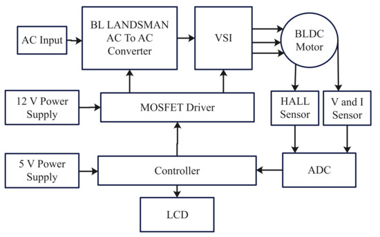
Figure 1.
Landsman converter-based power loss reduction in BLDC motor.
3. Simulation Results and Discussion
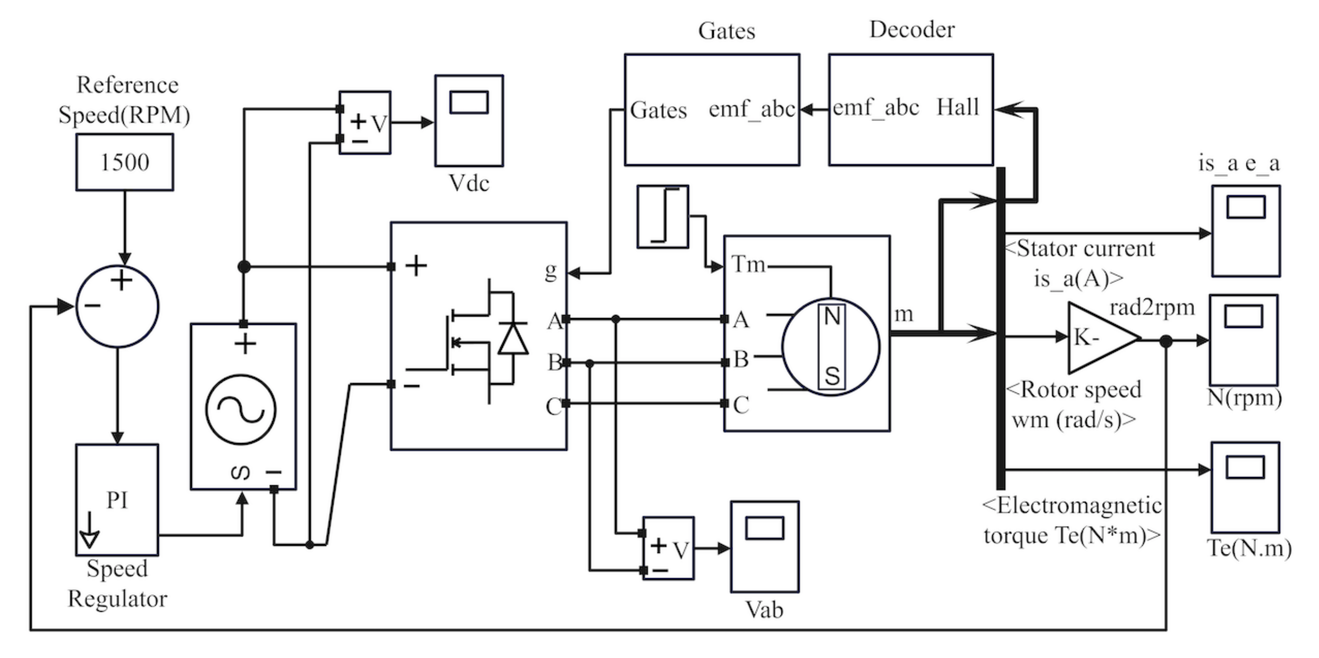
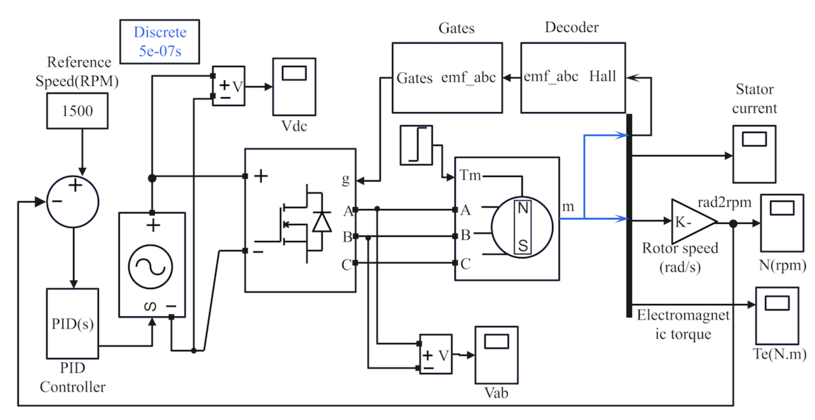
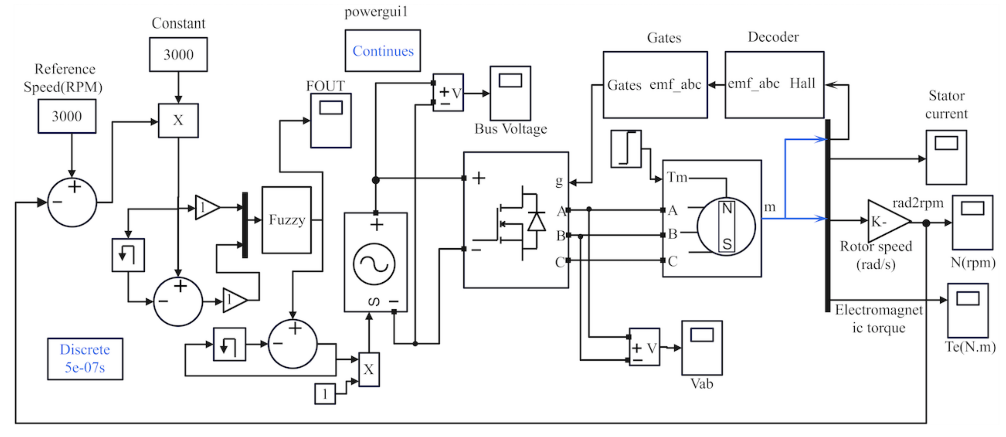
The Landsman converter operating in the DICM functions as an internal PF preregulator to achieve a unity PF at the alternating current mains. PFR based on a Landsman converter is designed to operate in DICM for natural PF regulation at alternating current mains. The BLDC motors are modeled and tested with three types of controllers, and the characteristic curves are taken. The controllers are designed in such a way that they are incorporated for better control action and good performance. The various curves are taken for different controllers and analyzed. The optimum design of a BLDC motor controller is chosen. Figure 2 shows the simulation circuit of the PI controller. The Simulink model consists of a speed regulator, gates, decoder, inverter, and BLDC motor. The input of the PWM inverter is a DC supply. The inverter output is fed by the BLDCM. The location and velocity of the rotor are sensed by the tacho generator model and hall sensor. The reference speed is related to the output of the tacho generator. Figure 3 represents the simulation circuit of the PID controller. The PID controller is working alone under normal operating conditions. This control strategy requires an external part for the BLDC motor to change operating conditions. PID controllers are simple and can be used in a variety of controlled plants, but they are incapable of providing good control performance in nonlinear and higher-order systems. The responses of the BLDC motor are observed to be improved with PI and PID-based controllers. It is revealed from this investigation that the speed controllers used have their advantages and disadvantages, and the choice is made depending on the requirements of a particular application. It is also noticed that PI and PID controllers are easy to implement. Figure 4 shows the fuzzy controller simulation circuit. A fuzzy controller contains the following modules: rule-based, fuzzification module, database, and defuzzification module along with the database. The fuzzification module and the defuzzification module have two steps each. The methods involved in these modules have various types that are explained in the three divisions, namely: crisp variables, data flow, and computational flow. The fuzzy controller input is normalized by dividing the difference in speed by the reference speed, so that the fuzzy controller becomes universal. An adaptive fuzzy controller that changes the slope of the membership function according to error is also designed.

Figure 2.
Simulation Model of PI controller for BLDC motor.
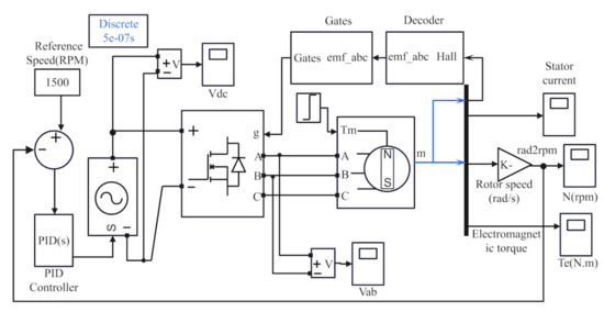
Figure 3.
Simulation model of PID controller for BLDC motor.
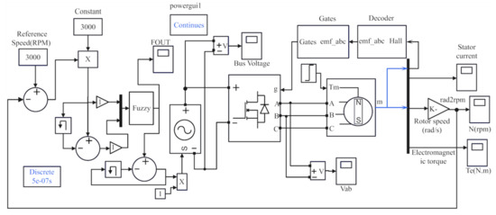
Figure 4.
Simulation model of fuzzy controller for BLDC motor.
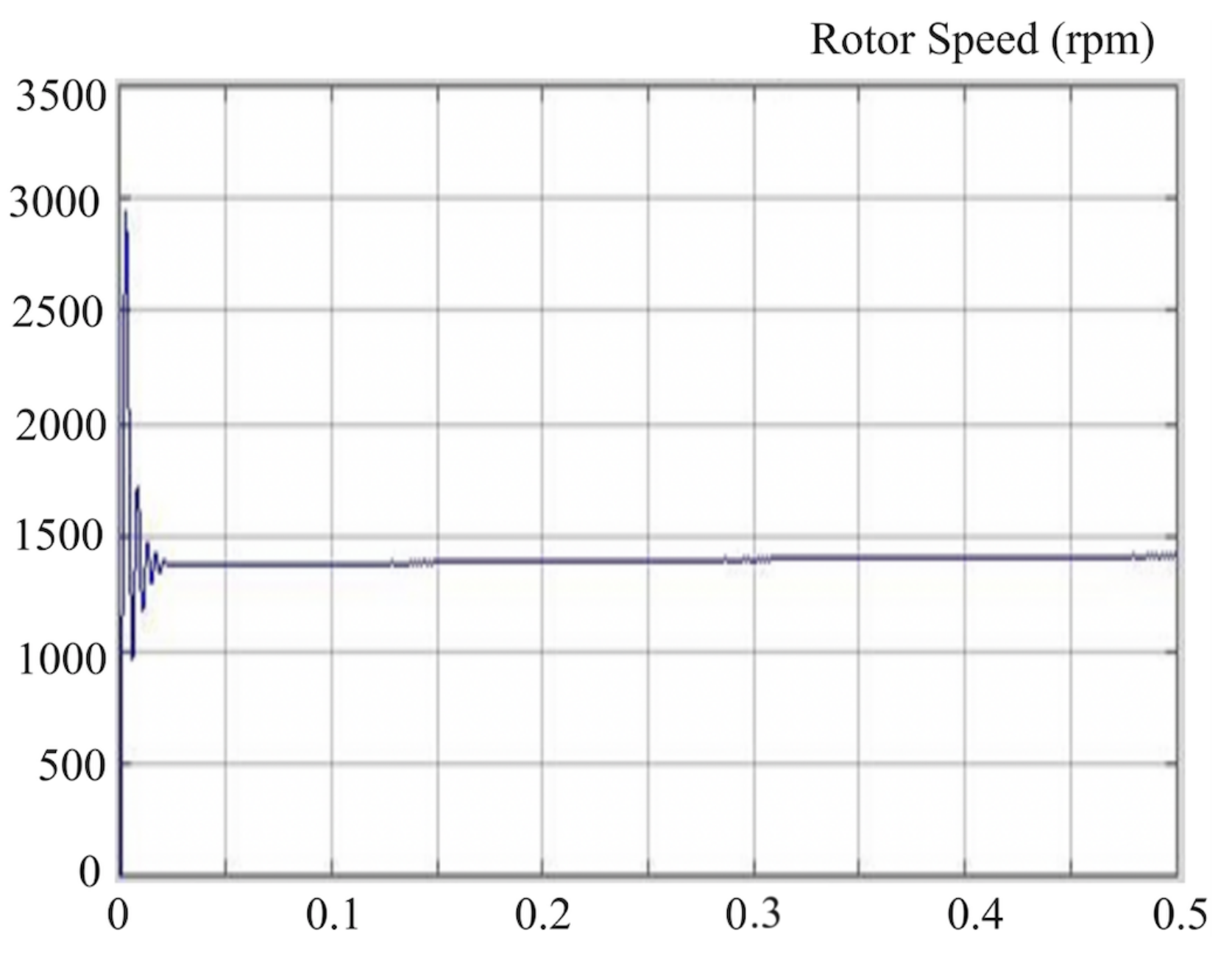
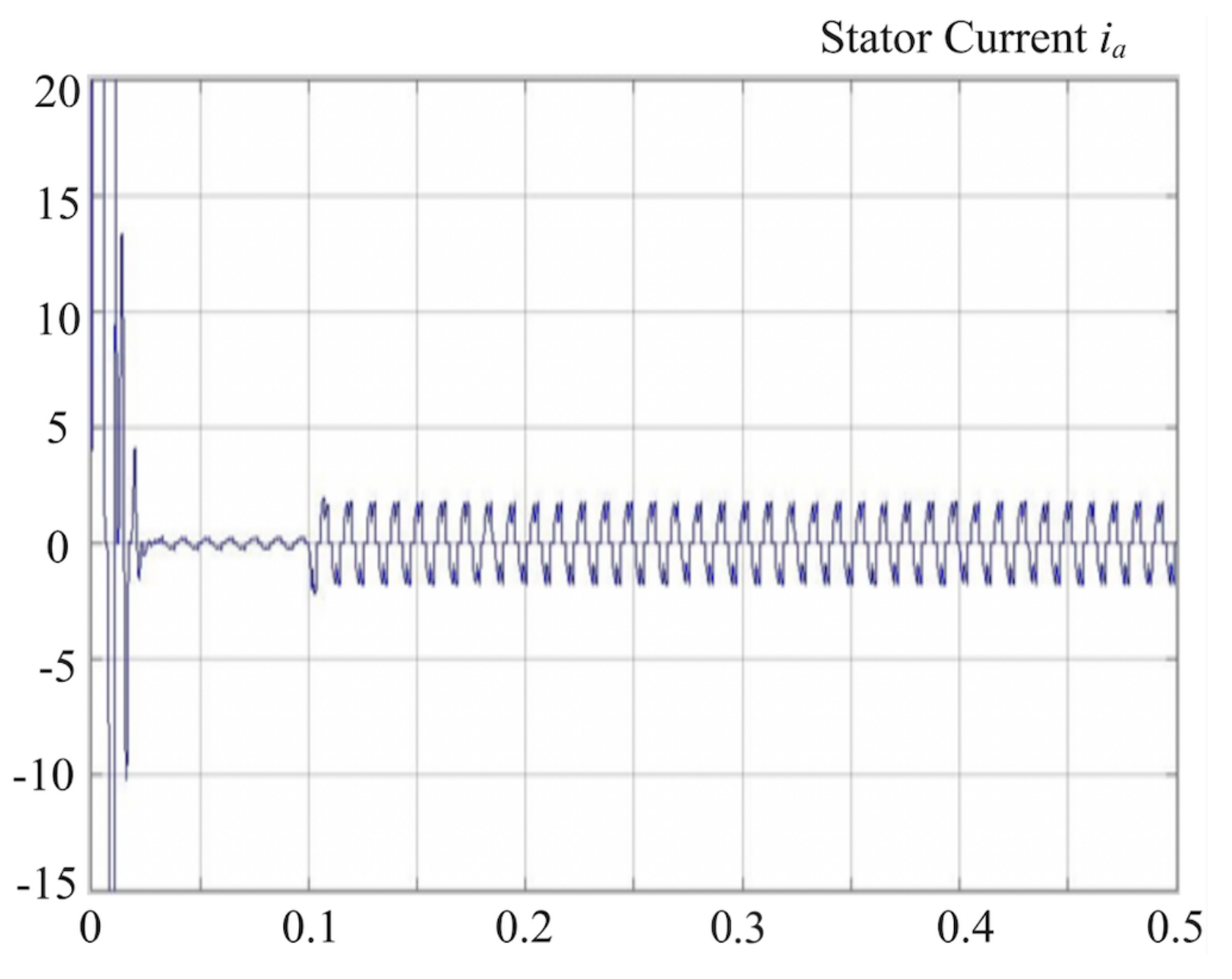
Table 1 shows the % power loss measurement using CSC and Landsman converter under various stages. Table 2 shows the voltage and current stress for the two configurations. It concludes that Landsman configuration gives better results when compared to CSC configuration. We measured power factor values of 0.9764 and 0.9896 for 60 V and 200 V, respectively. The results show that the proposed approach works well and is a useful Power Factor Correction for BLDCM. The obtained result explains the difference in power loss in PFC, VSI, and BLDCM for both the CSC converter and the Landsman converter, respectively. The two different voltages are 200 V and 60 V for both the converters. This graph shows that the Landsman converter has less power loss than the CSC converter. The simulation results show the waveforms of the input voltage and the output from the LC filter with load variation. When the filter output is fed into the BL Landsman converter, an output current and voltage are obtained. The simulation output of rotor speed for the PI controller is shown in Figure 5. Simulation results of BLDCM speed response through varying designs of fuzzy, fuzzy tuned PI, PID controller, and fuzzy tuned supervised offline fuzzy controllers, keeping constant load torque of 25 Nm with a reference speed of 1500 rpm. According to the response plots shown above, the drive achieves the reference or set speed in 1 s. The fuzzy variable structure controller attains the reference speed in 0.1 s. The reference speed for a fuzzy adjusted PID controller, on the other hand, was 0.064 s. A fuzzy tuned PID supervised offline ANFIS controller had a reference speed of 0.0611 s. Other response parameters like rise time, settling time, percentage of steady-state error, steady-state error, and peak overshoot are compared for different controllers. The simulation output of the stator current for the PID controller is shown in Figure 6. Figure 7 shows the simulation output of electromagnetic torque for the PID controller. From the above analysis, the fuzzy controller gives better performance in terms of characteristics. With new controllers, the BLDC motor has better settling time, steady-state error, and rise time characteristics.

Table 1.
Percentage Of Power Loss Comparison Between Csc Converter And Landsman Converter.
Table 2.
Comparison Between Voltage Stress And Current Stress Of CSC Converter And Landsman Converter.
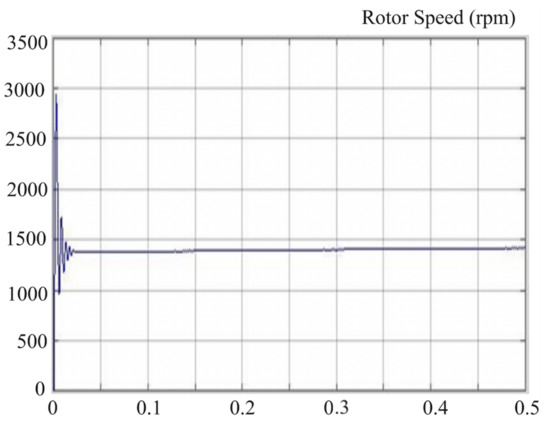
Figure 5.
Simulation output of rotor speed for PI controller.
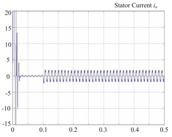
Figure 6.
Simulation output of stator current for PID controller.
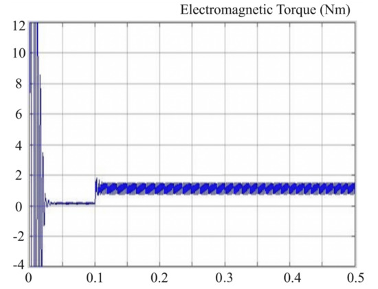
Figure 7.
Simulation output of electromagnetic torque for PID controller.
4. Experimental Setup
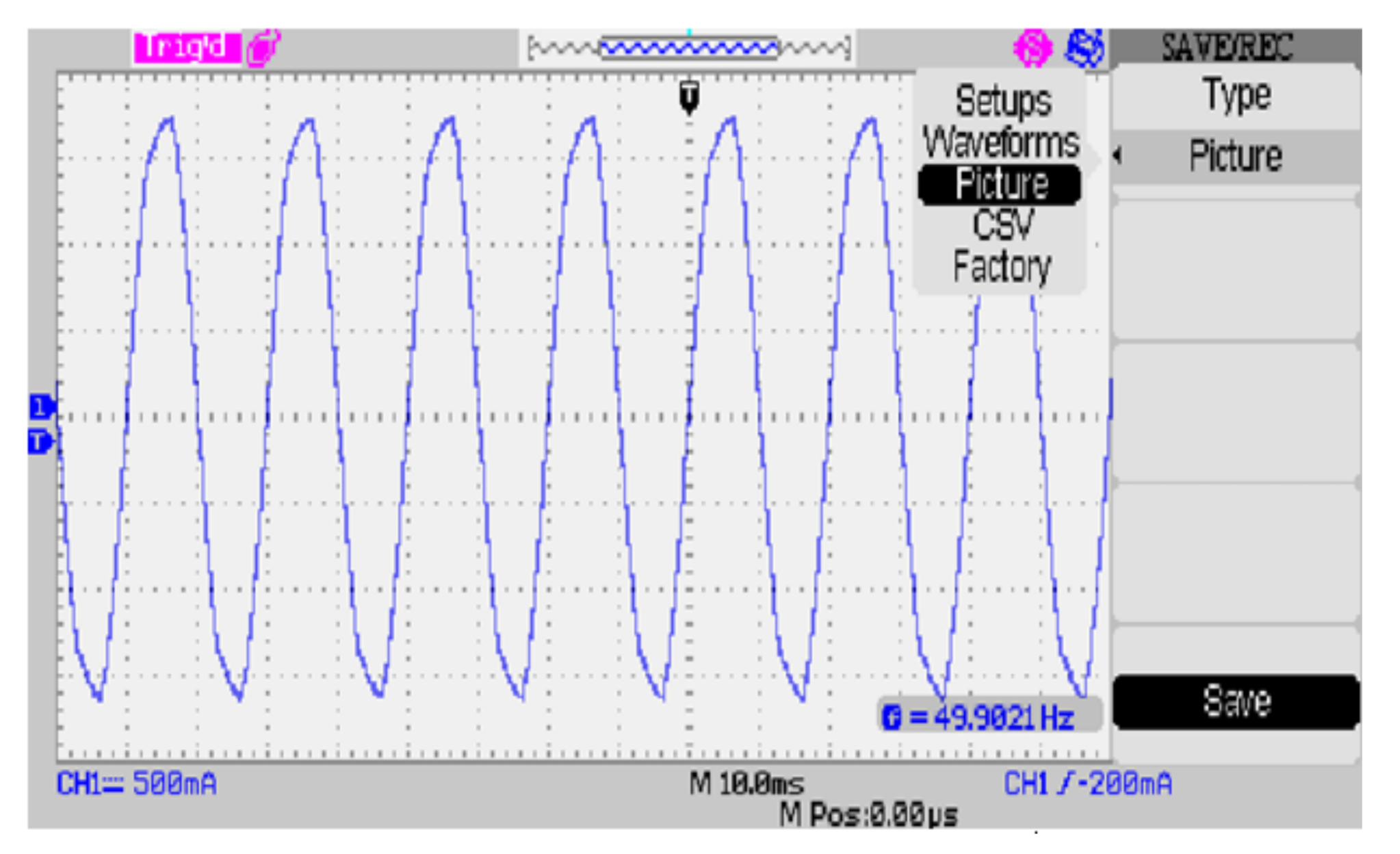
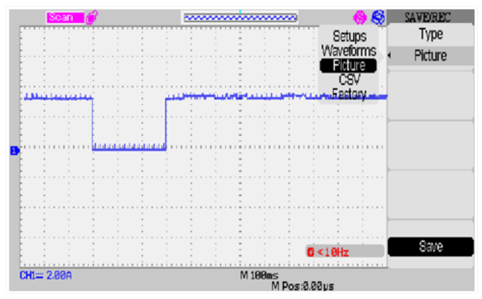
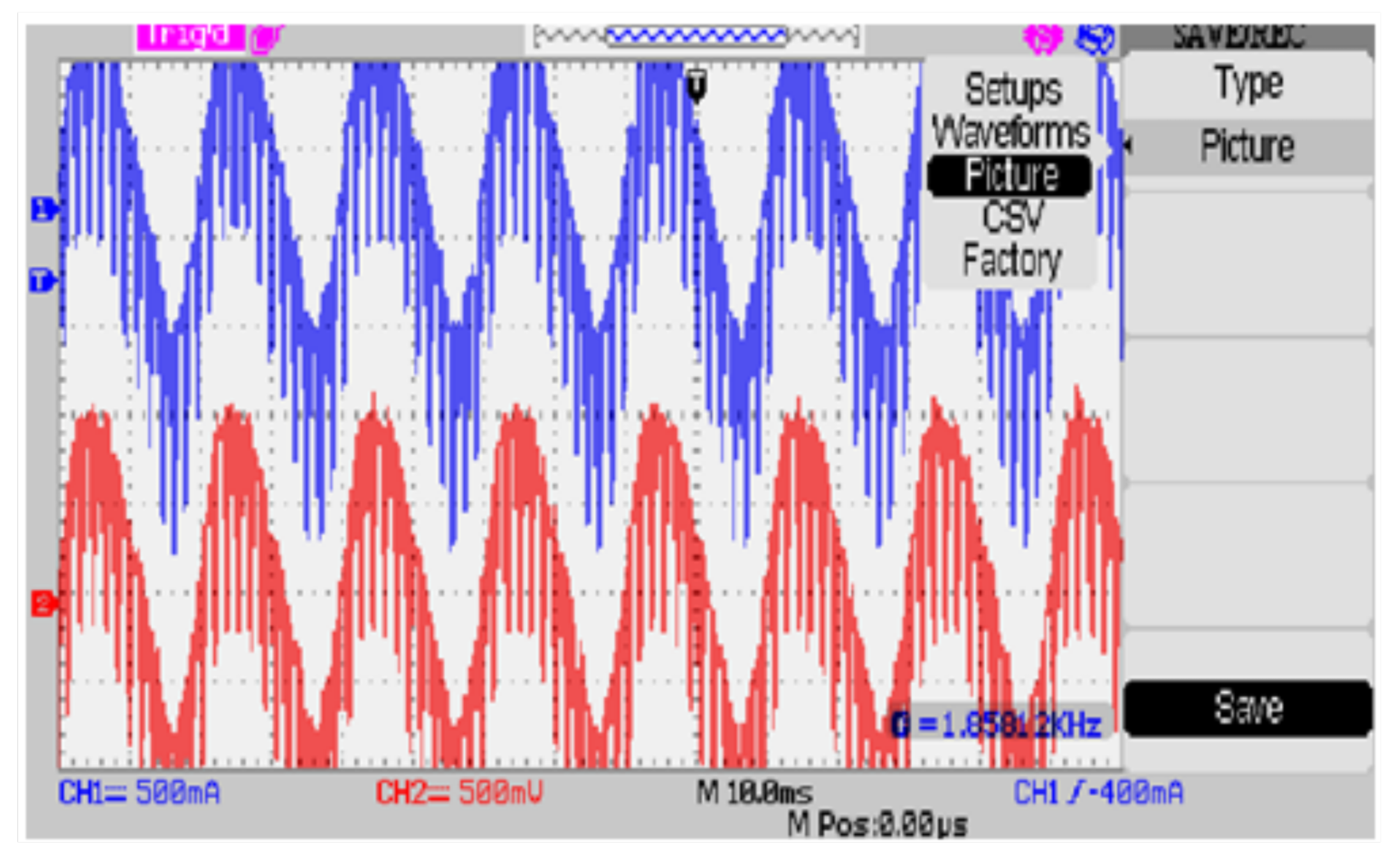
The experimental setup of the Landsman Converter based BLDC motor is represented in Figure 8. The experimental setup consists: MOSFET, BLDC motor, control inverter, RF transmitter, fluffy rationale controller, and RF receiver units. Three signs are produced by inherent lobby sensors. A single-stage AC source has been passed to the stage-controlled rectifier to convert AC to DC. Single-stage to three-stage converters are used to convert uncontrolled DC into controlled or pulse DC. The pulse DC is to run the BLDC motor. The Hall effect sensor senses the position of the rotor, and the flag is opened, which is passed to the microcontrollers. The implanted C coding program is scorched in IC 16F877A using the CCS compiler. The RF transmitter transmits the set speed, and the beneficiary gets and passes this information to the decoder. The speed of the real and the reference set is compared by the controller. The controller determines the error speed and the control signals are created. These control signals are sent to the inverter MOSFET circuit. These signals energize suitable windings by flipping the necessary switches in the inverter. In the experiment, a 2.2 kW BLDC motor is used. It is intended for low-power and variable-speed domestic applications. The motor’s performance has been found to be quite good for its operation at varying speeds over a wide range of supply. Figure 9 depicts the input waveform of the Landsman Converter. Experimental tests to show the control output of the BLDC motor’s Fuzzy Controller. In the experiment, two test cases are given, which are the sudden case of load variation and the fixed case of speed variation. Figure 10 shows the drive circuit input gate pulse 4. Figure 11 represents the output waveform for the phases R and Y of BLDCM. From the output of the experimental setup and simulation, the fuzzy controller gives better performance.
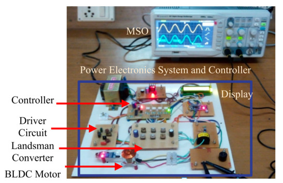
Figure 8.
Experimental setup of Landsman converter based BLDC motor drive.
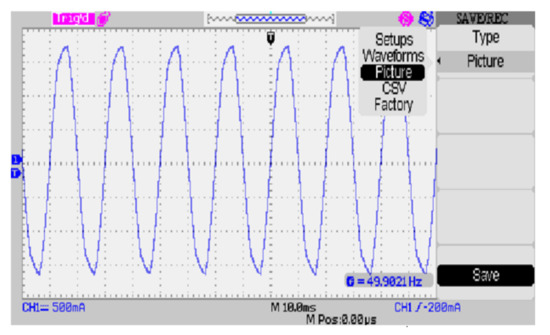
Figure 9.
Input waveform of the Landsman converter.
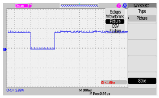
Figure 10.
Drive circuit input gate pulse 4.

Figure 11.
The output of the BLDC motor—phase R and phase Y.
5. Conclusions and Future Work
The Landsman Converter was proposed to minimize power losses in the BLDC motor drive. The fuzzy controller’s performance was compared with other controllers’ PI and PID for PFC. The results indicate the fuzzy controller is adaptive to the speed and load variations compared to other controllers. The proposed fuzzy logic controller circuit shows better performance regarding ripple torque reduction and good speed. Implementation of a Landsman converter in the BLDC motor to reduce the power factor correction. The power quality has been improved and now removes the ripples of the DC output. It was designed and established for low-power and domestic appliances. The simulation and hardware results concluded that the Landsman converter with a fuzzy-based controller has enhanced performance in terms of minimizing power loss and good power factor correction. Future work will consider the swarm optimizations based on intelligent controllers for the BLDCM velocity regulation to minimize time domain parameters, and it can be expanded to figure out the integral absolute error (IAE) of the above controllers.
Author Contributions
Conceptualization, N.S.K., G.C. (Gokul Chandrasekaran), J.T., V.K., G.C. (Gnanavel C.), N.P., M.S.B., M.G.H., F.F.M.E.-S. and M.M.A.; data curation, N.S.K., G.C. (Gokul Chandrasekaran), J.T., V.K., G.C. (Gnanavel C.), N.P., M.S.B., M.G.H., F.F.M.E.-S. and M.M.A.; formal analysis, N.S.K., G.C. (Gokul Chandrasekaran), J.T., V.K., G.C. (Gnanavel C.), N.P., M.S.B., M.G.H., F.F.M.E.-S. and M.M.A.; funding acquisition, F.F.M.E.-S.; Investigation, N.S.K., G.C. (Gokul Chandrasekaran), J.T., V.K., G.C. (Gnanavel C.), N.P., M.S.B., M.G.H. and M.M.A.; methodology, N.S.K., G.C. (Gokul Chandrasekaran), J.T., V.K., G.C. (Gnanavel C.), N.P., M.S.B., M.G.H. and M.M.A.; project administration, F.F.M.E.-S.; resources, N.S.K., G.C. (Gokul Chandrasekaran), J.T., V.K., G.C. (Gnanavel C.), N.P., M.S.B., M.G.H. and M.M.A.; Software, N.S.K., G.C. (Gokul Chandrasekaran), J.T., V.K., G.C. (Gnanavel C.), N.P., M.S.B., M.G.H. and M.M.A.; supervision, N.P. and M.S.B.; validation, N.S.K., G.C. (Gokul Chandrasekaran), J.T., V.K., G.C. (Gnanavel C.), N.P., M.S.B., M.G.H., F.F.M.E.-S. and M.M.A.; visualization, N.S.K., G.C. (Gokul Chandrasekaran), J.T., V.K., G.C. (Gnanavel C.), N.P., M.S.B., M.G.H., F.F.M.E.-S. and M.M.A.; writing—original draft, N.S.K., G.C. (Gokul Chandrasekaran), J.T., V.K., G.C. (Gnanavel C.), N.P. and M.S.B.; writing—review and editing, N.S.K., G.C. (Gokul Chandrasekaran), J.T., V.K., G.C. (Gnanavel C.), N.P., M.S.B., M.G.H., F.F.M.E.-S. and M.M.A. All authors have read and agreed to the published version of the manuscript.
Funding
The authors extend their appreciation to the Deputyship for Research & Innovation, Ministry of Education in Saudi Arabia for funding this research work through the project number ID:1289.
Institutional Review Board Statement
Not applicable.
Informed Consent Statement
Not applicable.
Data Availability Statement
Not applicable.
Conflicts of Interest
The authors declare no conflict of interest.
References
- Bhaskaran, P.E.; Maheswari, C.; Thangavel, S.; Ponnibala, M.; Kalavathidevi, T.; Sivakumar, N. IoT Based monitoring and control of fluid transportation using machine learning. Comput. Electr. Eng. 2021, 89, 106899. [Google Scholar] [CrossRef]
- Priyanka, E.; Maheswari, C.; Thangavel, S.; Bala, M.P. Integrating IoT with LQR-PID controller for online surveillance and control of flow and pressure in fluid transportation system. J. Ind. Inf. Integr. 2020, 17, 100127. [Google Scholar] [CrossRef]
- Maheswari, C.; Priyanka, E.; Thangavel, S.; Vignesh, S.; Poongodi, C. Multiple regression analysis for the prediction of extraction efficiency in mining industry with industrial IoT. Prod. Eng. 2020, 14, 457–471. [Google Scholar] [CrossRef]
- Maheswari, C.; Ramya, A.; Priya, B.M.; Sudhahar, S.; Prabhu Raj, B.; Lokesh, B.; Ramani, G. Analysis and optimization on the biodegradable plate making process parameters using RSM-based Box–Behnken Design method. J. Mater. Cycles Waste Manag. 2021, 23, 2255–2265. [Google Scholar] [CrossRef]
- Sathyan, A.; Milivojevic, N.; Lee, Y.J.; Krishnamurthy, M.; Emadi, A. An FPGA-based novel digital PWM control scheme for BLDC motor drives. IEEE Trans. Ind. Electron. 2009, 56, 3040–3049. [Google Scholar] [CrossRef]
- Singh, P.K.; Singh, B.; Bist, V.; Al-Haddad, K.; Chandra, A. BLDC motor drive based on bridgeless landsman PFC converter with single sensor and reduced stress on power devices. IEEE Trans. Ind. Appl. 2017, 54, 625–635. [Google Scholar] [CrossRef]
- Shao, J.; Nolan, D.; Teissier, M.; Swanson, D. A novel microcontroller-based sensorless brushless DC (BLDC) motor drive for automotive fuel pumps. IEEE Trans. Ind. Appl. 2003, 39, 1734–1740. [Google Scholar] [CrossRef]
- Awadallah, M.A.; Morcos, M.M.; Gopalakrishnan, S.; Nehl, T.W. A neuro-fuzzy approach to automatic diagnosis and location of stator inter-turn faults in CSI-fed PM brushless DC motors. IEEE Trans. Energy Convers. 2005, 20, 253–259. [Google Scholar] [CrossRef]
- Bist, V.; Singh, B. A reduced sensor PFC BL-Zeta converter based VSI fed BLDC motor drive. Electr. Power Syst. Res. 2013, 98, 11–18. [Google Scholar] [CrossRef]
- Bist, V.; Singh, B. An adjustable-speed PFC bridgeless buck–boost converter-fed BLDC motor drive. IEEE Trans. Ind. Electron. 2013, 61, 2665–2677. [Google Scholar] [CrossRef]
- Premkumar, K.; Manikandan, B. Adaptive Neuro-Fuzzy Inference System based speed controller for brushless DC motor. Neurocomputing 2014, 138, 260–270. [Google Scholar] [CrossRef]
- Singh, B.; Kumar, R. Solar photovoltaic array fed water pump driven by brushless DC motor using Landsman converter. IET Renew. Power Gener. 2016, 10, 474–484. [Google Scholar] [CrossRef]
- Vanchinathan, K.; Valluvan, K. A metaheuristic optimization approach for tuning of fractional-order PID controller for speed control of sensorless BLDC motor. J. Circuits Syst. Comput. 2018, 27, 1850123. [Google Scholar] [CrossRef]
- Zhou, Y.; Li, H.; Meng, G.; Zhou, S.; Cao, Q. Analytical calculation of magnetic field and cogging torque in surface-mounted permanent-magnet machines accounting for any eccentric rotor shape. IEEE Trans. Ind. Electron. 2014, 62, 3438–3447. [Google Scholar] [CrossRef]
- Wang, Y.; Xuhui, W. Analysis of multi-phase permanent magnet motors with concentrated non-overlapping stator windings. In Proceedings of the 2010 International Conference on Electrical Machines and Systems, Incheon, Korea, 10–13 October 2010; pp. 1088–1093. [Google Scholar]
- Sikora, A.; Zielonka, A.; Woźniak, M. Minimization of Energy Losses in the BLDC Motor for Improved Control and Power Supply of the System under Static Load. Sensors 2022, 22, 1058. [Google Scholar] [CrossRef] [PubMed]
- Sikora, A.; Woźniak, M. Impact of Current Pulsation on BLDC Motor Parameters. Sensors 2021, 21, 587. [Google Scholar] [CrossRef] [PubMed]


Publisher’s Note: MDPI stays neutral with regard to jurisdictional claims in published maps and institutional affiliations. |
© 2022 by the authors. Licensee MDPI, Basel, Switzerland. This article is an open access article distributed under the terms and conditions of the Creative Commons Attribution (CC BY) license (https://creativecommons.org/licenses/by/4.0/).