Article

Wideband Ring-Monopole Flexible Antenna with Stub for WLAN/C-Band/X-Band Applications

1
Department of AI Convergence Network, Ajou University, Suwon 16499, Korea
2
Department of Electrical and Computer Engineering, Ajou University, Suwon 16499, Korea
*
Author to whom correspondence should be addressed.
Appl. Sci. 2022, 12(21), 10717; https://doi.org/10.3390/app122110717
Submission received: 28 September 2022 / Revised: 21 October 2022 / Accepted: 21 October 2022 / Published: 22 October 2022

Abstract

:
In this paper, we designed a flexible antenna operating in the WLAN/C-band/X-band and analyzed the antenna bending characteristics. It is advantageous to have a wide bandwidth because the resonant frequency of the flexible antenna can be changed when it is bent. The proposed antenna was designed based on a ring monopole antenna with broadband characteristics. Slots and t-strip lines to the ring, stubs to the feed, and stepped structures to the ground plane were added to increase bandwidth. As a result of analyzing the characteristics of the proposed antenna when bent through the S-parameter, it was confirmed that the proposed antenna is suitable at the target frequency, even if it is bent. The size of the antenna is 0.256 λ × 0.32 λ × 0.0016 λ ( 32 × 40 × 0.2   mm 3 ) at 2.4 GHz, and the antenna bandwidth is 15.68% (2.36 GHz~2.87 GHz) at 2.615 GHz and 111.69% (3.4 GHz~12 GHz) at 7.7 GHz.

1. Introduction

With the recent development of wearable device technology, flexible antennas have been studied extensively [1,2,3]. For smaller and lighter wearable devices, it is necessary to miniaturize the antenna and develop a flexible antenna that can operate in various frequency bands. As the demand for wearable devices operating in WLAN/C-band/X-band increases, research on flexible antennas for these frequency bands is required.
Because flexible antennas change their characteristics when bent, they may not operate at the target resonant frequency. If the bandwidth of the antenna is wide, it becomes easier to operate at the target resonant frequency even if the characteristics change. A great deal of research has been carried out on wideband flexible antenna in the ultra-wideband (UWB), but the antenna operating in the UWB band does not operate in the WLAN band to avoid signal interference [4,5,6,7,8,9,10]. However, there are many wearable devices that use frequency bands such as WIFI and Bluetooth included in the WLAN band. Therefore, it is necessary to study a wideband flexible antenna including a WLAN band. In addition, since high frequency is used in many communication technologies such as 5G and satellite communication, the demand for wearable devices operating in C-band and X-band is also increasing. Flexible broadband antennas covering the WLAN band have also been studied. However, some antennas did not cover the X-band [11,12,13], although there have been studies on antennas covering the WLAN, C-band, and X-band, which required miniaturization for ease of installation [14,15,16]. There was a study on an antenna that covered WLAN, C-band, and X-band with a small size, but since it was a rigid antenna, the characteristics of bending could not be guaranteed [17]. Therefore, to cover WLAN, C-band, and X-band, a flexible antenna with a smaller size than the existing antenna is required.
A flexible antenna using a conventional circular or elliptical patch can have broadband characteristics. However, if the flexible antenna is bent, cracks may occur on the radiating surface. The ring-type patch has the advantage that it does not crack even when bent compared to the conventional circular or elliptical patches. Ring-type monopoles also have broadband characteristics [18,19,20]. Therefore, if the flexible antenna is designed as a ring-type monopole with broadband characteristics, it has the advantage of strong crack resistance. In addition, the slots and t-strip lines can be added to the ring to increase bandwidth.
Flexible antennas were fabricated using various dielectric materials for the substrate. Although not films, there were flexible antennas proposed as substrates that could have flexible characteristics with a very thin thickness such as Rogers 5880, Rogers Ro4835 [21,22]. However, the flexible antenna proposed as a dielectric without film properties has a disadvantage in that it is difficult to break or return to a flat state once bent. The most commonly used dielectrics for flexible antenna films are liquid crystal polymers (LCPs), polyethylene terephthalate (PET), and polyimides [23,24,25,26]. The disadvantage of LCP is that it is difficult to obtain. On the other hand, polyimide is suitable for flexible antennas because it has higher electrical insulation than PET and is easy to obtain. Polyimide was selected as a dielectric in this paper because it is easy to bend, has good electrical insulation, and is easy to obtain.
In this paper, we propose a wideband flexible ring monopole antenna. A CPW (coplanar waveguide) feeding structure is used in which the signal line and ground are on the same plane. The CPW feeding structure is suitable for flexible antennas because the antenna is thinner and easier to bend. It is also advantageous for impedance matching [27,28,29]. Slots and t-strip lines to the ring, stubs to the feed, and stepped structures to the ground plane were added to increase bandwidth. The antenna was designed using a commercial electromagnetic simulator HFSS. The designed antenna has a size of 0.256 λ × 0.32 λ × 0.0016 λ ( 32 × 40 × 0.2   mm 3 ) at 2.4 GHz and was fabricated by printing copper on 0.2 mm thick polyimide. The measurement data such as S-parameters, radiation pattern, and gain were compared with the simulation results. In addition, the characteristics of the designed antenna were analyzed in terms of the degree of bending in the horizontal and vertical directions.

2. Antenna Design and Parametric Study

2.1. Antenna Design

The proposed antenna is shown in Figure 1, and Table 1 shows the length of each element of the antenna. The feeding method uses a CPW feeding line with a transmission line width of 1.5 mm (Wf) and a distance between the transmission line and the ground of 0.2 mm (g) on both sides. The step structure of the ground plane helps impedance matching with an optimized length by parametric study and the stub is bar-shaped with a length of 10.5 mm (Wsh1) and a height of 1.9 mm (Lsh1). The t-strip line is designed by 10.5 mm (Lt1) bars and 8.9 mm (Wt2) bars. The antenna uses polyimide with a thickness of 0.2 mm and a dielectric constant of 3.5 as a substrate and has a size of 32 × 40   mm 2 . It is designed to operate in WLAN/X-band/C-band using ANSYS HFSS.
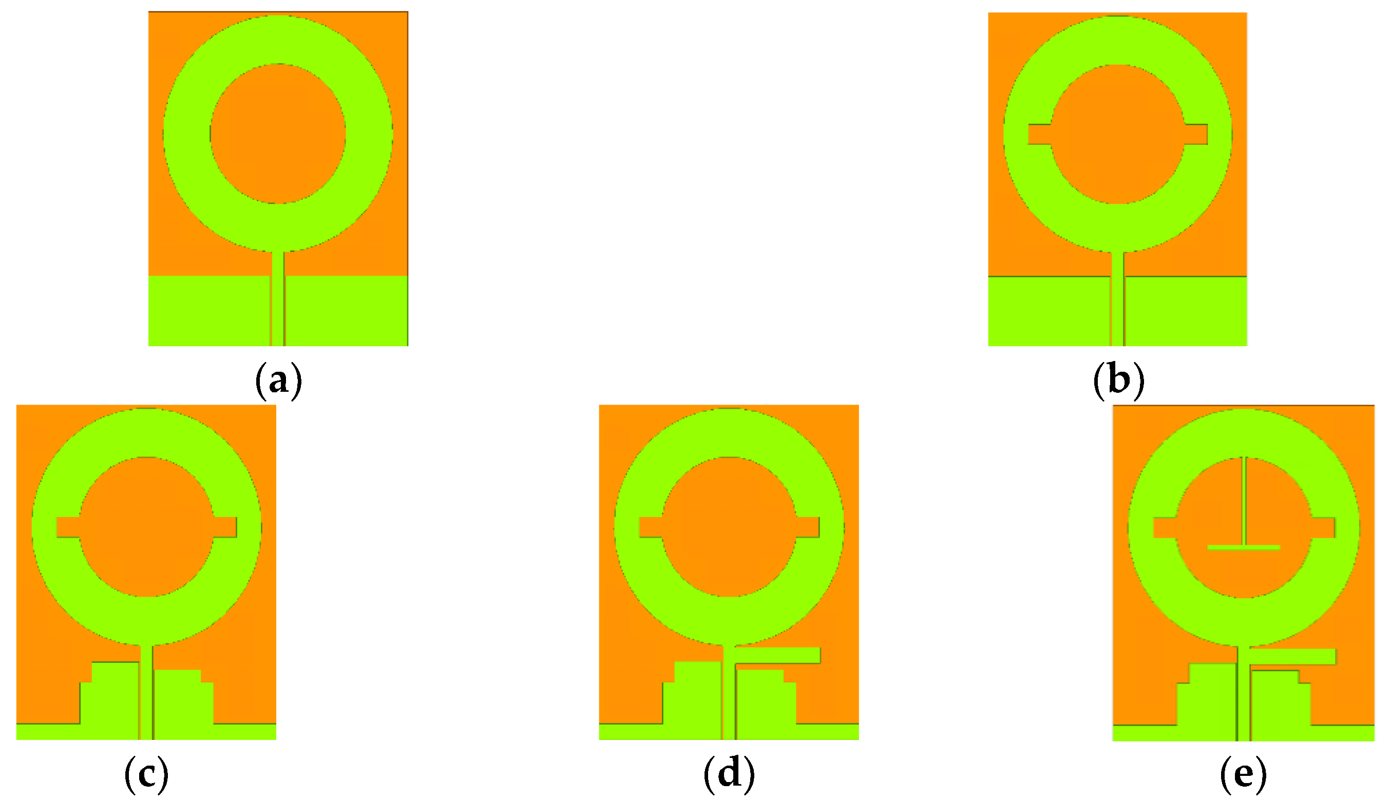
The antenna was designed according to the procedure shown in Figure 2, and the S-parameter of the antenna according to each procedure is shown in Figure 3. As shown in Figure 2a, antenna 1 was designed with a ring-type monopole using a CPW feeding method. The ring-type monopole can have broadband characteristics and is more resistant to cracks than the solid type. As shown in Figure 3, antenna 1 operates in the 2.46~2.55 GHz, 3.96~5.11 GHz. Thus, it was necessary to improve the bandwidth of antenna 1. To improve the impedance matching, a slot was added to the ring of antenna 2 in Figure 2b. As shown in Figure 3, the S-parameter of the antenna 1 was only −15 dB at 4.6 GHz, but the S-parameter of antenna 2 was −25 dB at 4.6 GHz. In antenna 3 of Figure 2c, a step structure was added to the ground for impedance matching [30]. The S-parameter of antenna 3 shows that it operates at 2.33~3.02 GHz, 3.92~5.22 GHz, 7.33~9.40 GHz due to the step structure of the ground plane that achieves impedance matching. After that, the stub was placed between the ring and the feed part as shown in antenna 4 of Figure 2d. The proposed antenna uses a stub to make a resonance point between the existing C-band and X-band to achieve a wide bandwidth without a notch [31,32]. When the stub operates as a λ/4 monopole at 5~7.5 GHz, the antenna can cover the entire C-band and X-band. The length of the stub is designed to include both C-band and X-band. As a result, the S-parameter of antenna 4 shows that it operates at 2.38~3.27 GHz and 4.95~11.65 GHz. In antenna 5 of Figure 2e, a t-strip line inside a ring-shaped monopole was added to improve the bandwidth. The t-strip line is designed to have a resonance point at 3.5 GHz [33]. Note that antenna 5 finally operated at WLAN/C-band/X-band and 5G sub-bands (3.4~3.7 GHz).
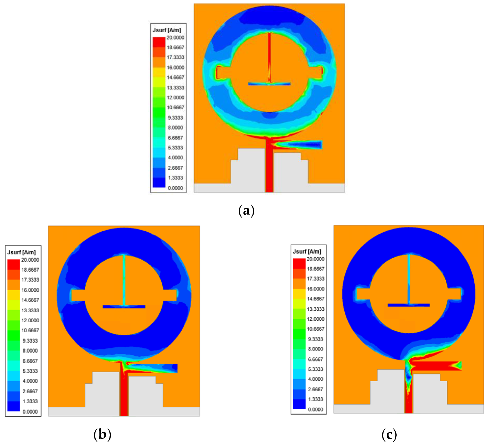
Figure 4 is the current distribution of the final designed antenna, which explains the operating principle of the proposed antenna. Figure 4a shows the current distribution of 2.4 GHz. It can be seen that the ring part is a radiating element in the 2.4 GHz band, the lowest frequency band of the proposed antenna because of a relatively strong current in the ring part unlike the other frequencies in Figure 4b,c. The proposed antenna did not operate at 3.5 GHz before the t-strip line was added. Figure 4b shows the current distribution of 3.5 GHz and a strong current flow in the t-strip line, which means that the proposed antenna operates at 3.5 GHz due to the t-strip line. The stub was designed to be 10.5 mm long to operate as a λ/4 monopole in 5~7.5 GHz. Figure 4c shows a strong current flowing through the stub at 7.5 GHz. This means that the stub works as designed.

2.2. Parametric Study

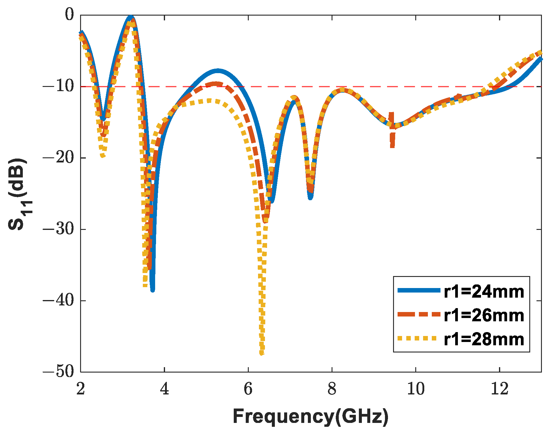
Figure 5 shows the S-parameter results of a parametric study when the sizes of r1 are different. r1 is the size of the diameter of the ring and has a great influence on the antenna characteristics. Depending on the value of r1, the S-parameter value of the C-band changes. When r1 is 24 mm, the antenna does not operate in the 4.68~5.82 GHz. Meanwhile, the 5.1~5.8 GHz band is an upper band of the WLAN band. Since it does not operate in this range, there is an advantage that it can be used as an UWB antenna that can avoid signal interference with the WLAN band. The diameter of the ring of the proposed antenna is designed to have margins for S-parameters so that it can operate in a wideband without a notch.
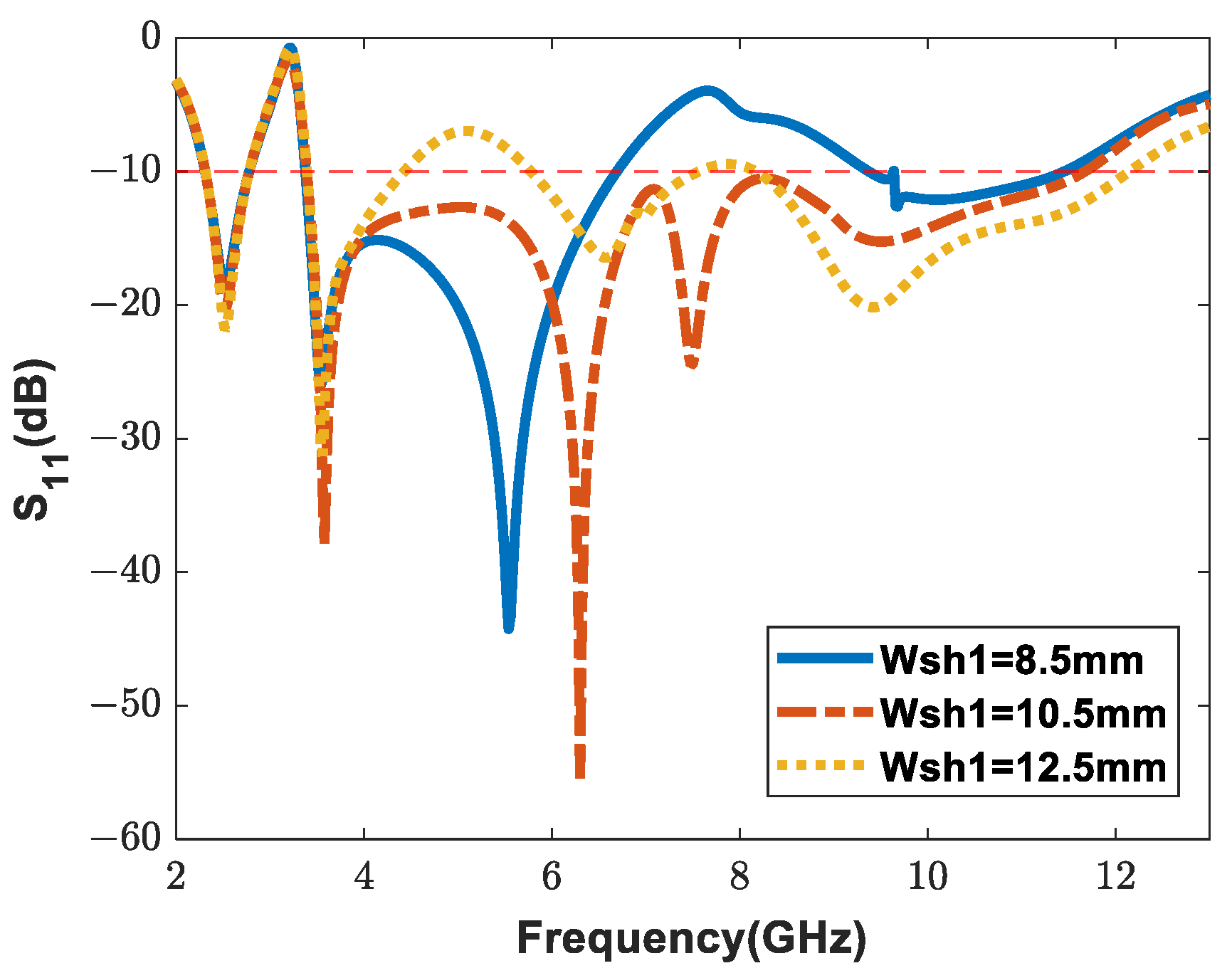
Figure 6 shows the S-parameter results of a parametric study when the sizes of Wsh1 are different. Wsh1 is the length of the stub and has a great influence on the impedance matching of the antenna. The stub is designed to operate as a λ/4 monopole. However, the stub is close to the feeding part, which greatly affects the overall antenna characteristics. The stub length of the proposed antenna is designed to operate over a wider bandwidth by operating between the C-band and X-band.

3. Antenna Fabrication and Analysis

3.1. Antenna Fabrication and Antenna Characteristics

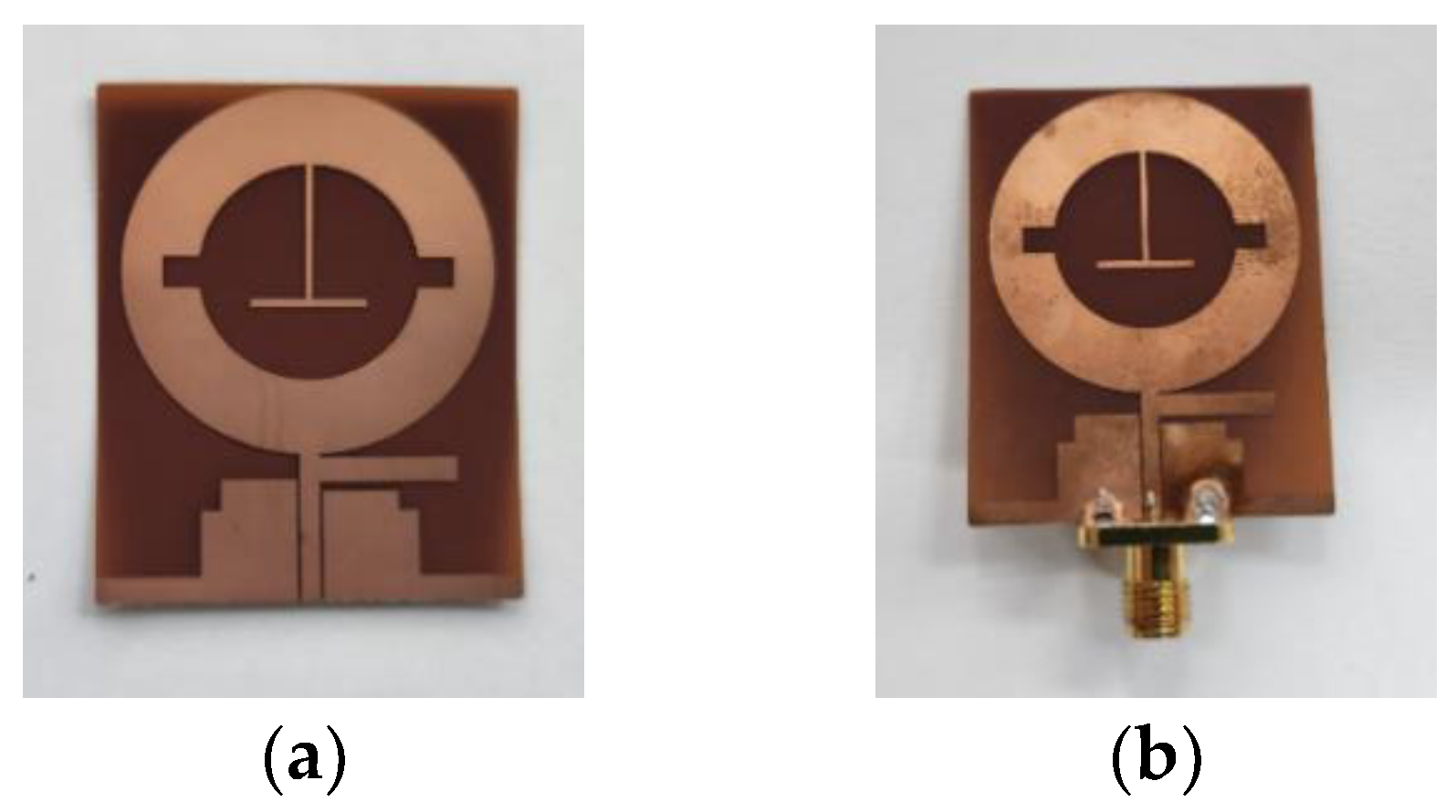
The antenna was fabricated by printing a copper radiating surface on a 0.2 mm polyimide substrate with a dielectric constant of 3.5. Figure 7 is a picture of the fabricated antenna and a picture of when the SMA connector was attached for measurement. S-parameters were measured using the vector network analysis (VNA) model ZVA67. In addition, gain measurement was performed at the Korea Electromagnetic Waves Technology Institute.
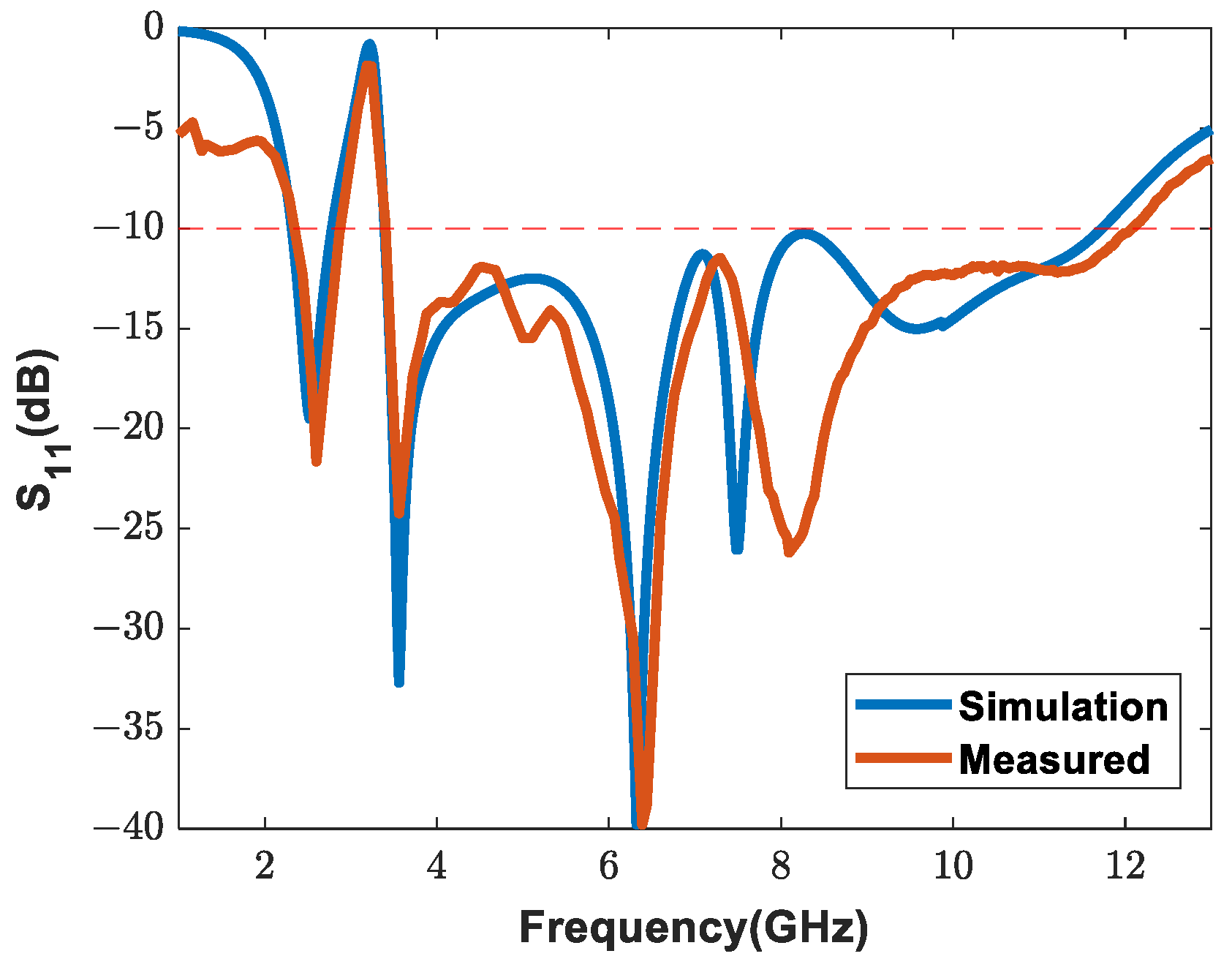
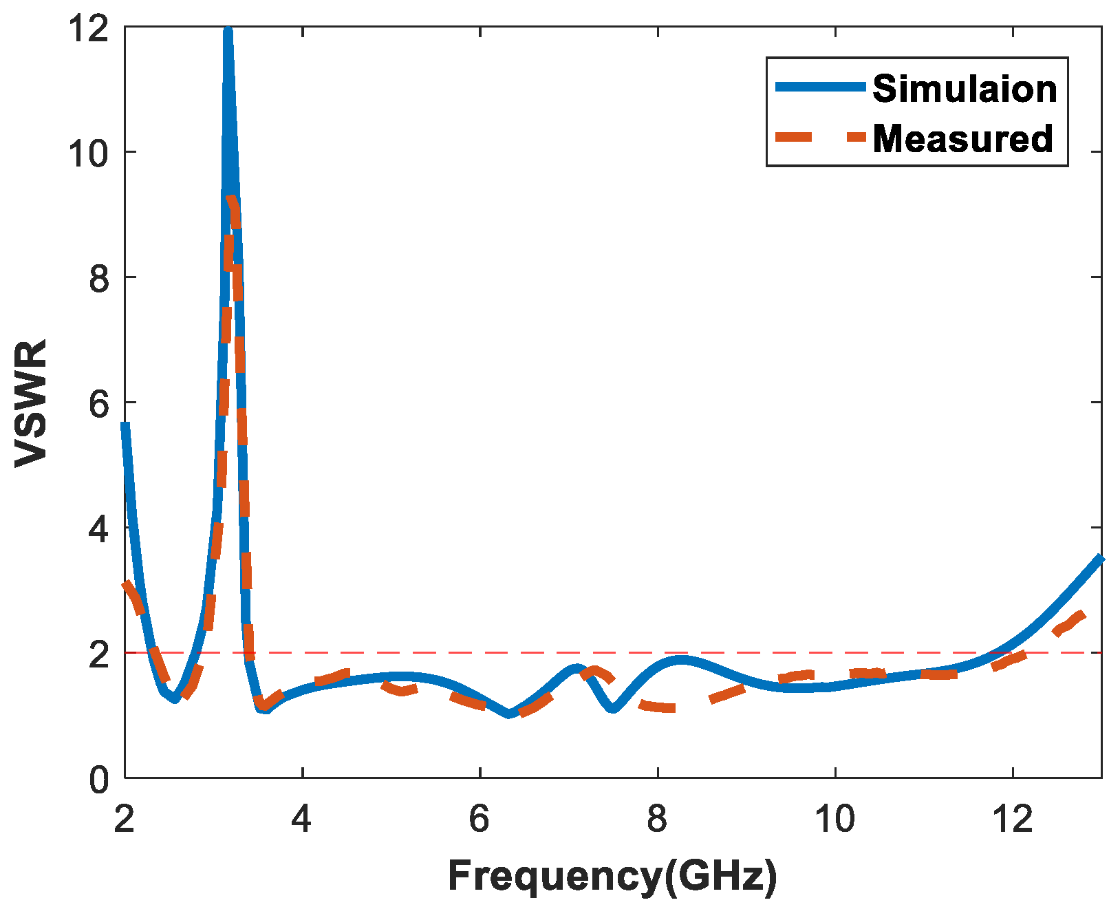
Figure 8 compares the results of measuring the S-parameter of the manufactured antenna and the S-parameter of the simulation. Furthermore, Figure 9 compares the matching characteristics of the fabricated antenna with the simulation using VSWR. The measured data and simulations show reasonably consistent graphs. There is a slight difference between the simulation result and the measurement result. This could be seen as the effect of soldering the SMA connector to the measurement antenna and the loss effect of the connected cable. The simulation results and measurement results differ more at high frequencies than at low frequencies. This is because the antenna is more sensitive to soldering or connected cables at high frequencies. In the simulation, the S-parameter was formed below −10 dB in the band of 2.31~2.78 GHz, 3.39~11.73 GHz. However, in the measured value, it had a bandwidth of 2.36 GHz~2.87 GHz, 3.4 GHz~12 GHz. The measured results showed that the antenna could operate in WLAN (2.4~2.48 GHz, 5.1~5.8 GHz)/C-band (4~8 GHz)/X-band (8~12 GHz).
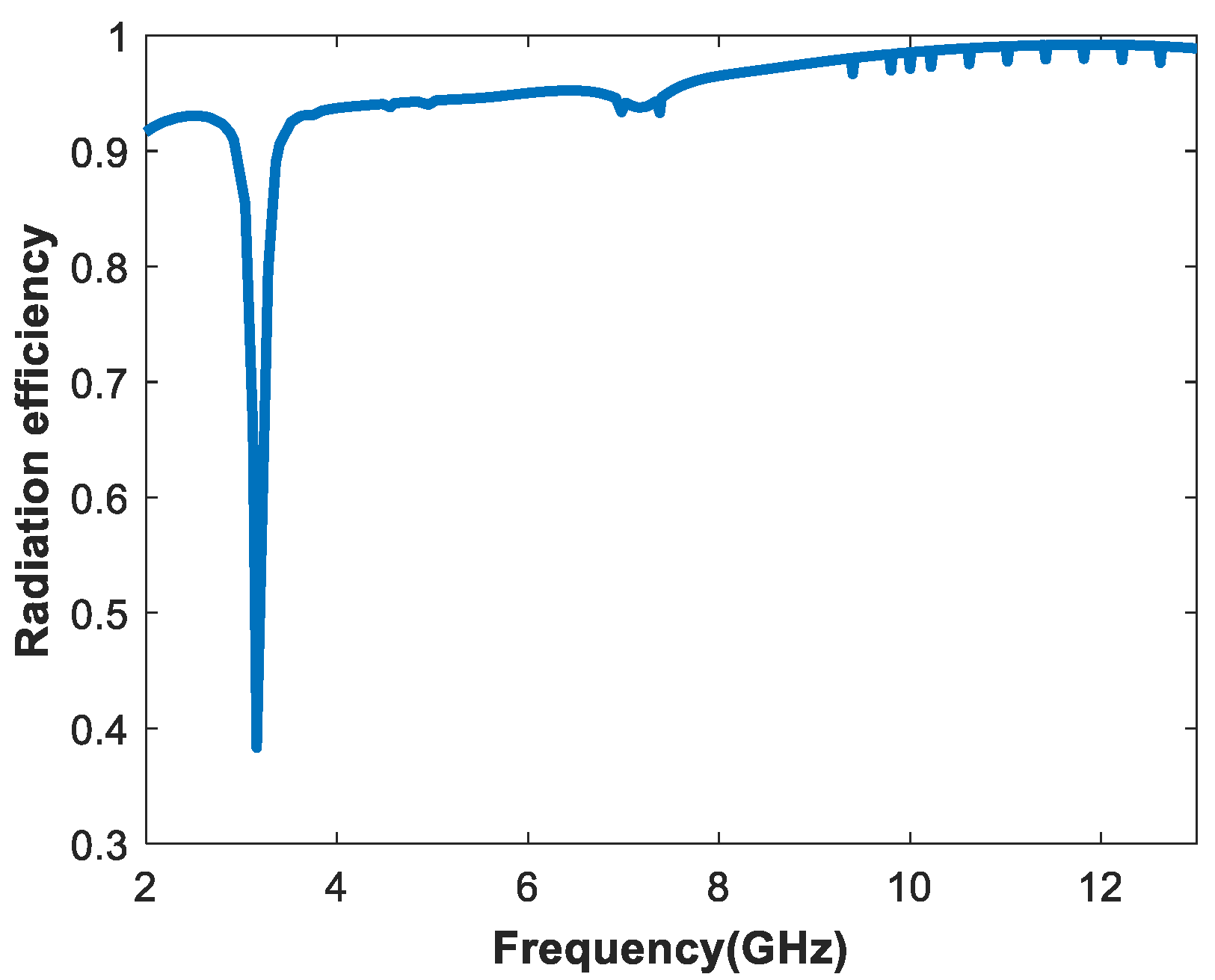
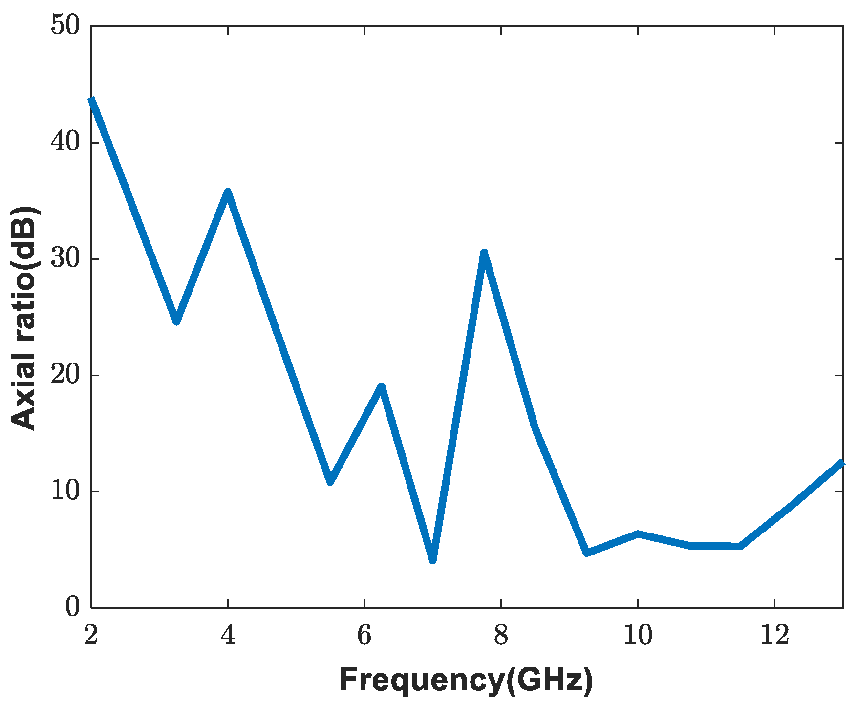
The radiation efficiency and polarization of the proposed antenna are shown by simulation. Figure 10 is the simulated radiation efficiency of the proposed antenna, and Figure 11 is the axial ratio of the proposed antenna. Radiation efficiency was close to 100% at the antenna operating bandwidth. The axial ratio showed that the proposed antenna had a linear polarization.
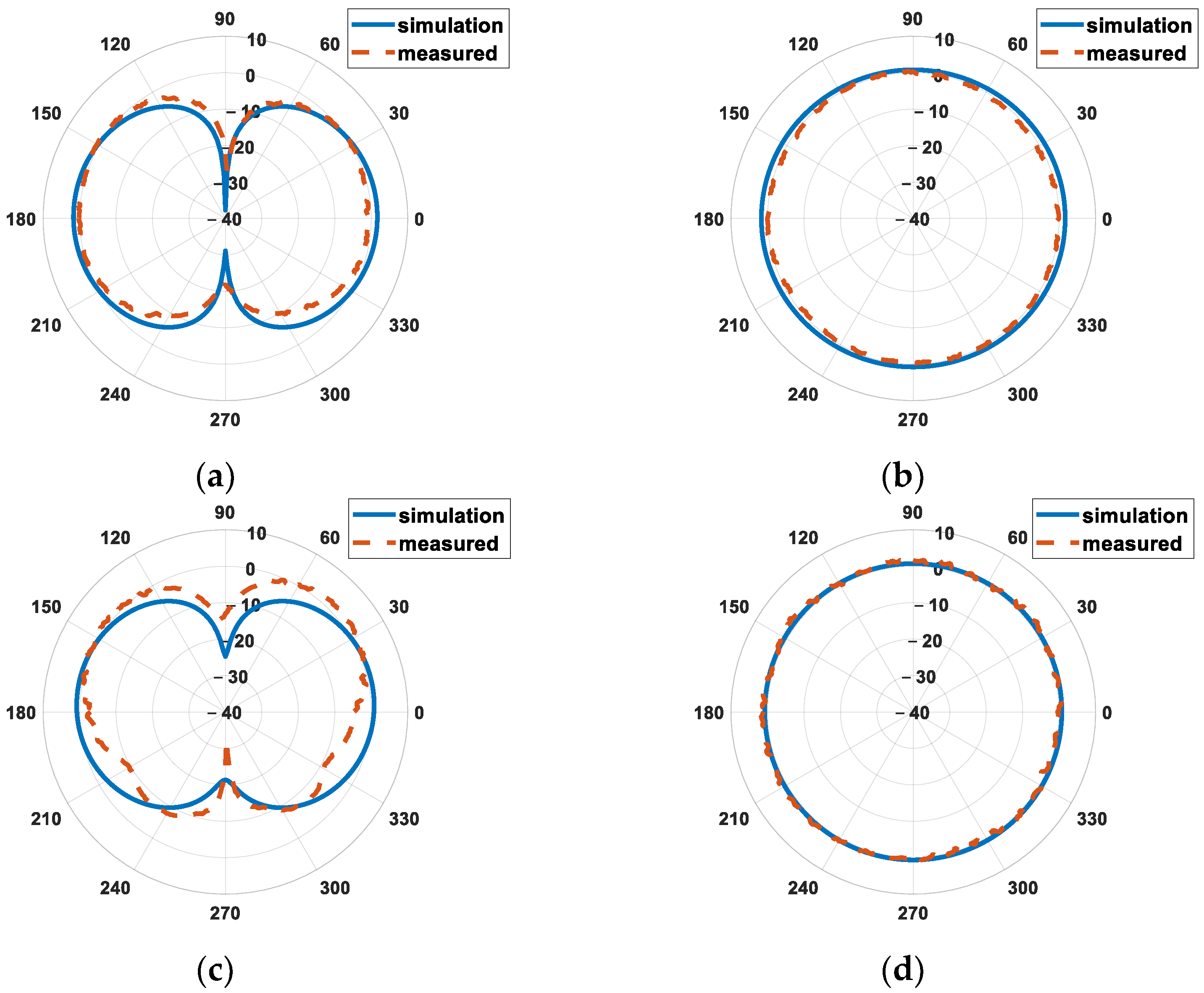
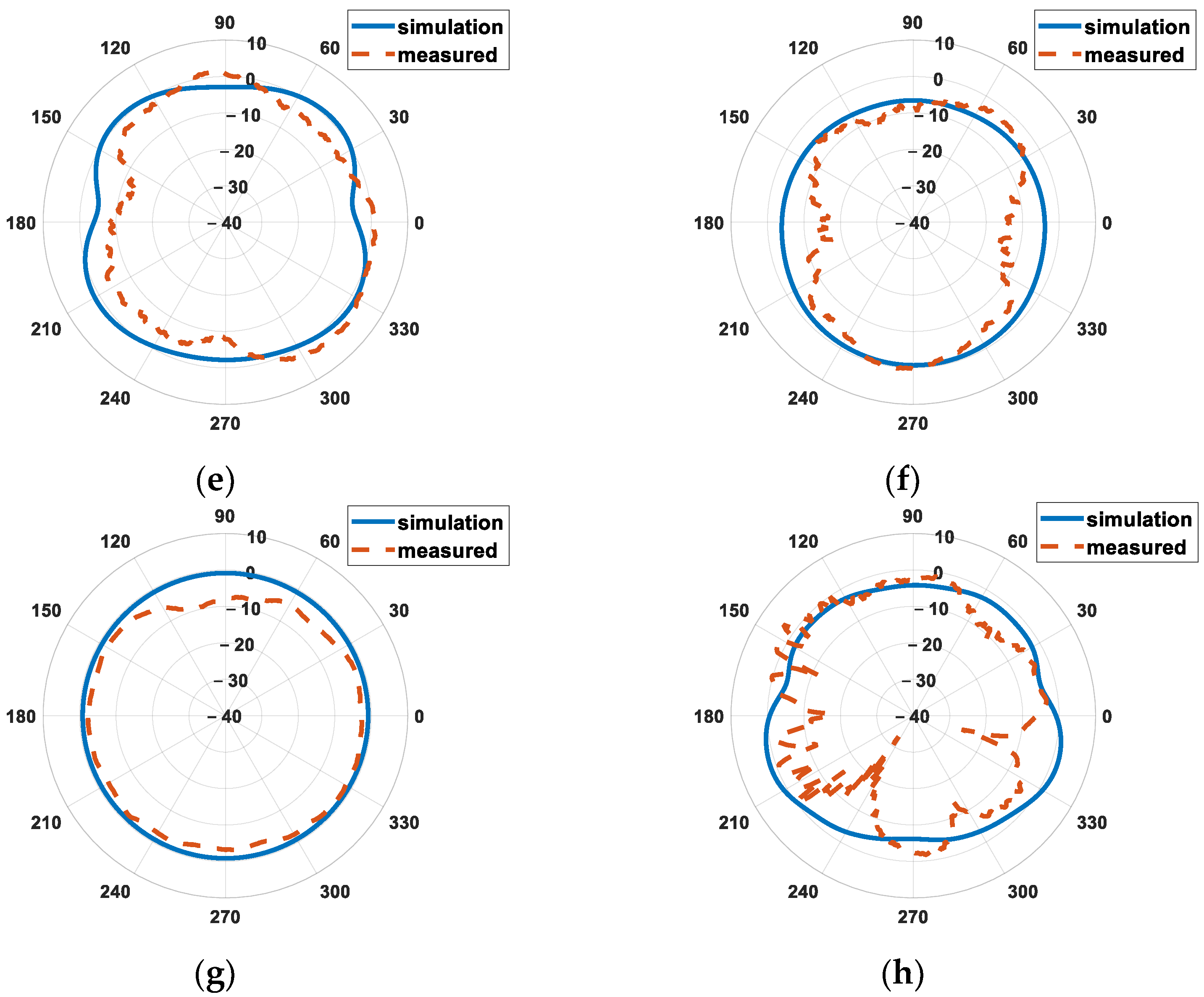
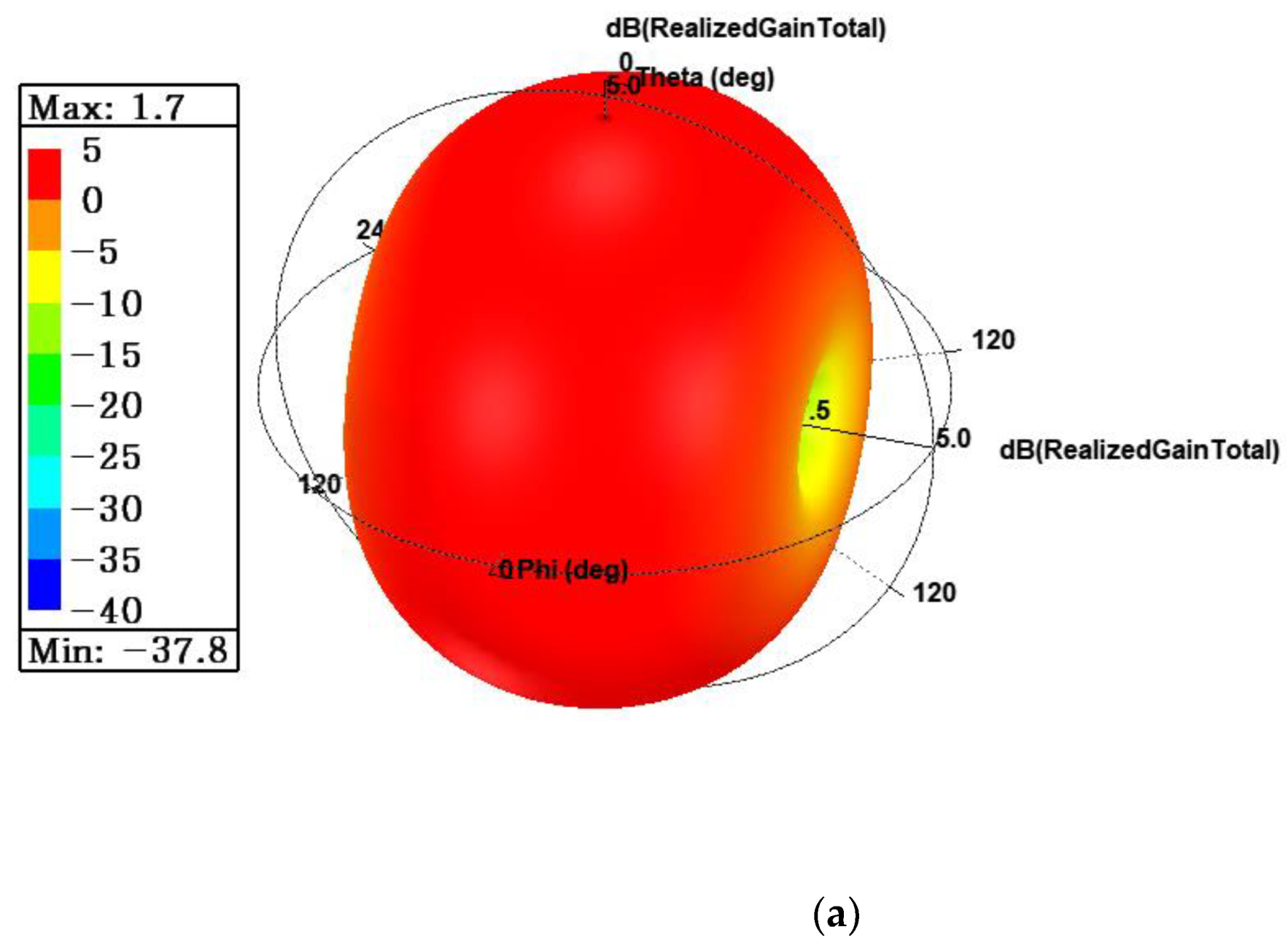
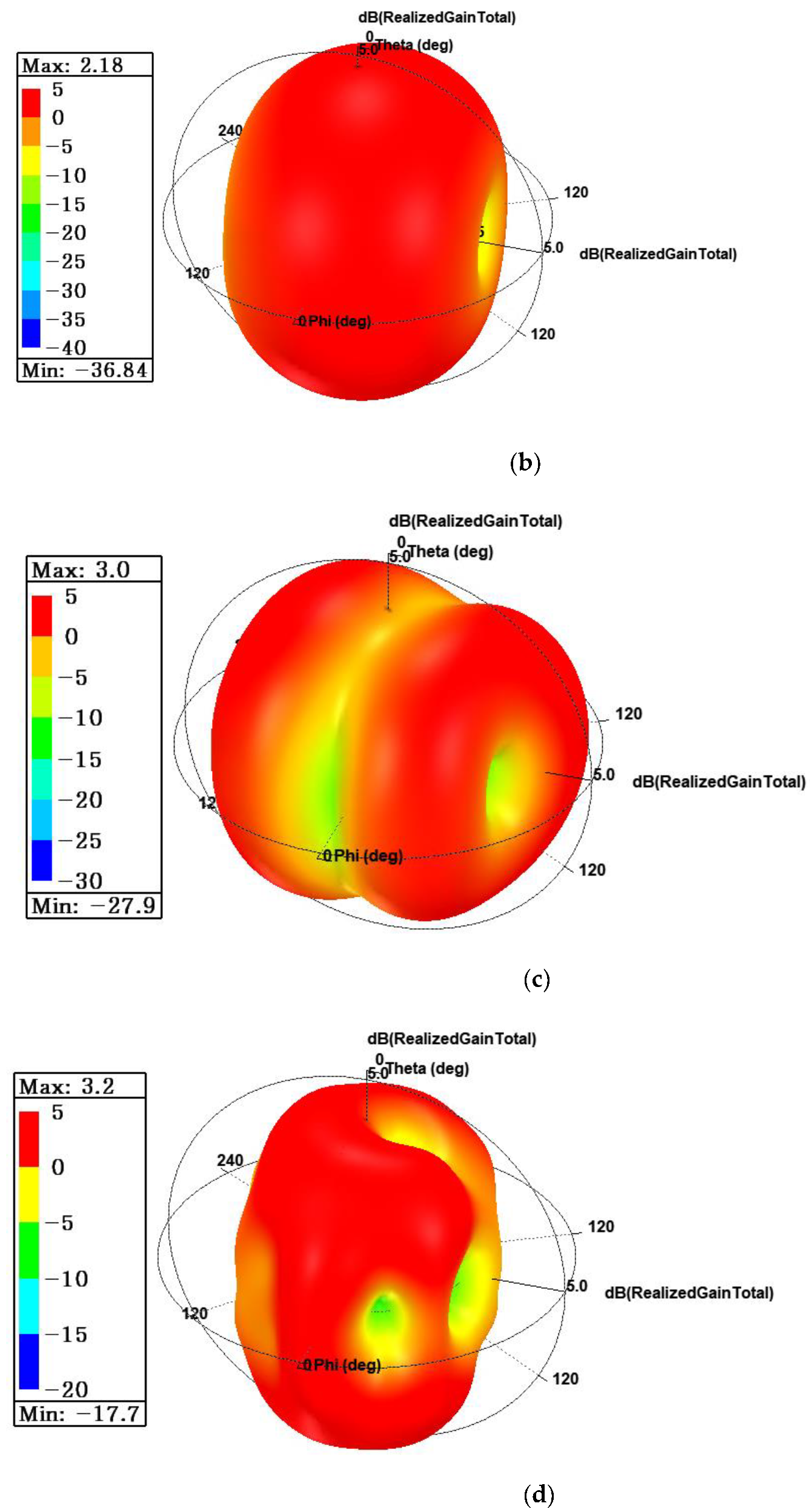
Figure 12 compares the 2D radiation patterns between measurements and simulations at 2.4, 3.5, 6.3, and 10 GHz, which appeared as resonance frequency in S-parameters. At 2.4 and 3.5 GHz, a radiation pattern close to omnidirectional is shown, but the distortion of the radiation pattern as it goes to a high frequency is due to the high order mode. The proposed antenna had a gain of 1.3 dB at 2.4 GHz, 1.6 dB at 3.5 GHz, 1.3 dB at 6.3 GHz, and 1.7 dB at 10 GHz. Figure 13 is a simulated 3D radiation pattern. The 3D radiation pattern showed that the antenna was distorted by the higher-order mode at high frequencies.
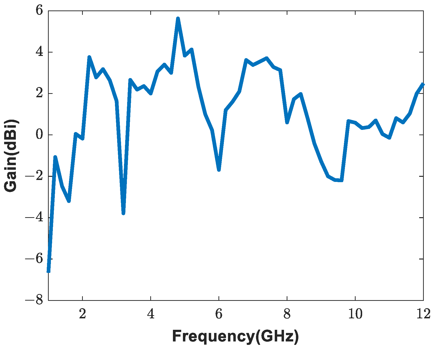
Figure 14 shows the peak gain of the antenna for each frequency. The gain was the lowest at 2.87~3.4 GHz, where the antenna was not operating. Furthermore, compared with Figure 8, in the band where the antenna operates, it can be confirmed that the S-parameter had a large influence on the gain tendency. The reason that the gain of the antenna is not constant is that the radiation pattern is distorted as the antenna operates in a higher-order mode at high frequencies. Although the graph is not smooth, the effect on the application is small because the tendency does not change. Table 2 shows a comparison with the antenna parameters of the references. The proposed antenna had the smallest physical size of the flexible antennas operating in the WLAN/C-band/X-band.

3.2. Bending Characteristics

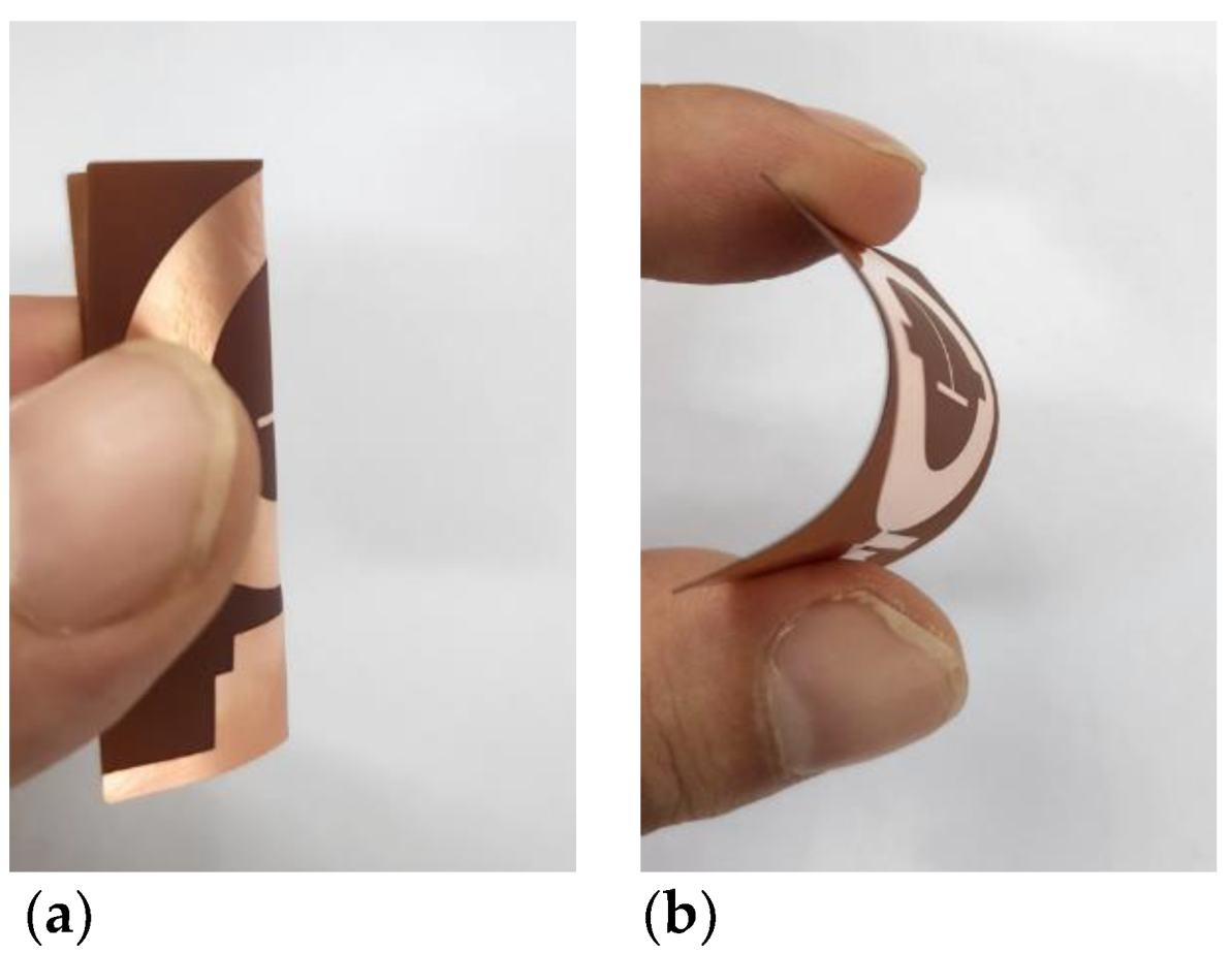
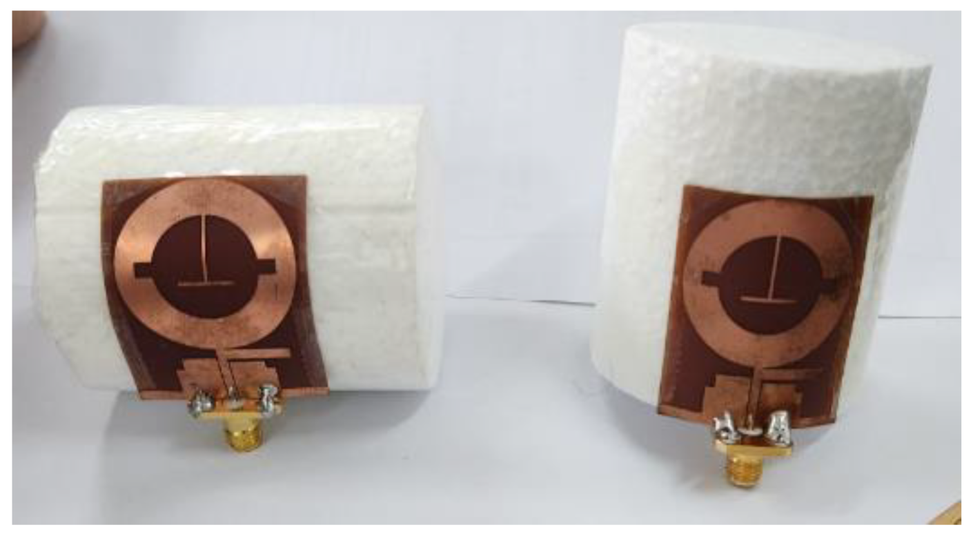
Figure 15 is a photograph of when the proposed antenna was bent in the horizontal and vertical directions by hand, and it can be seen that the antenna was bent without any problem. If the antenna is bent by hand, the exact degree of bending is unknown. However, if the antenna is bent with a cylindrical Styrofoam, as in Figure 16, the bending degree of the antenna can be quantified by the radius. Styrofoam was used for measurement because it is commonly available at low cost and is a material that does not have much effect on the antenna.
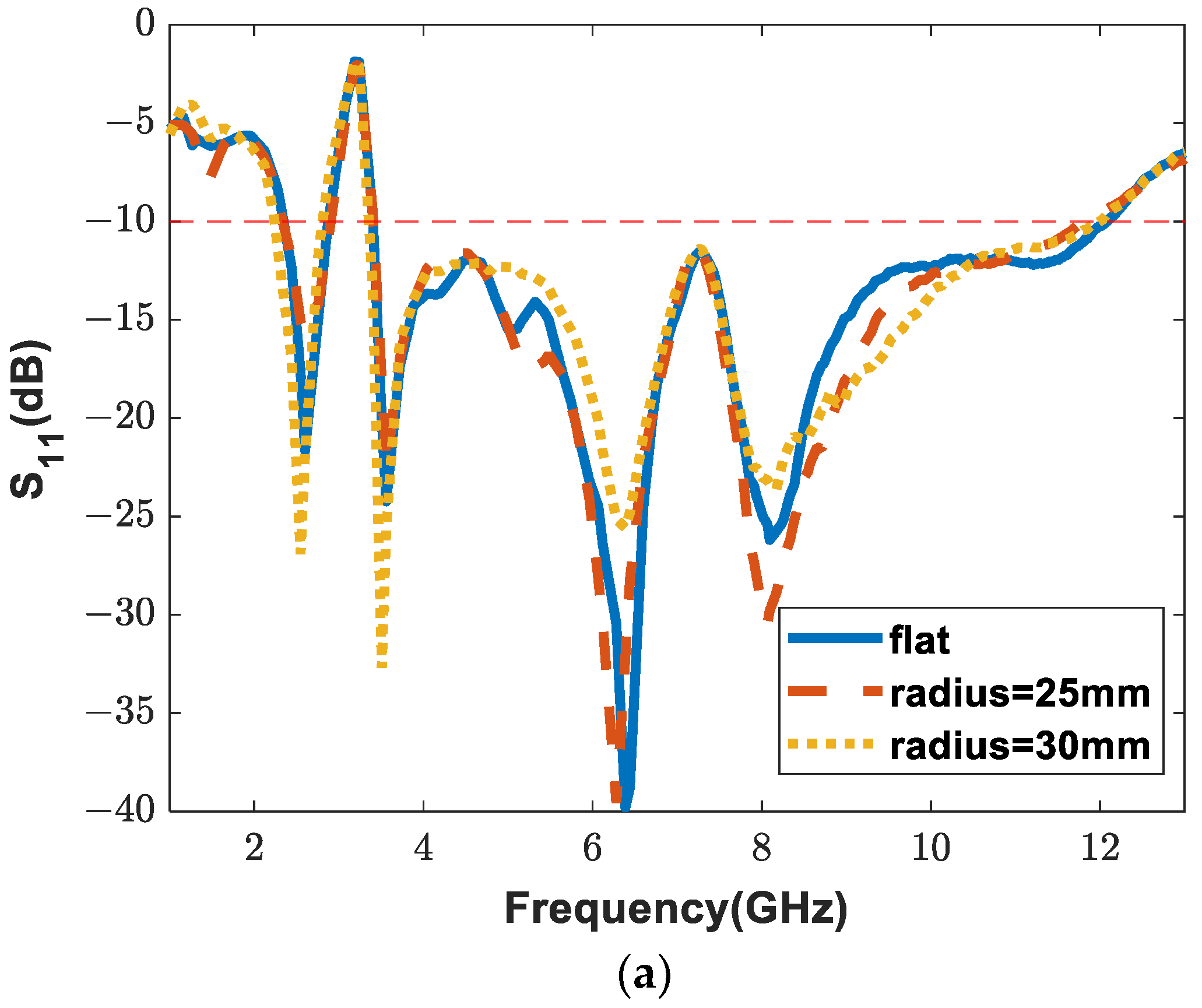
Figure 17 shows the S-parameter results measured when bent both horizontally and vertically round a cylindrical Styrofoam with radii of 25 mm and 30 mm. Radii of 25 mm and 30 mm correspond to the bending angles of 73 and 61 degrees, respectively, when bent horizontally, and 92 and 76 degrees, respectively, when bent vertically.
When the antenna was bent, the S-parameter of the antenna changed. As a result of measuring the S-parameter according to the degree of horizontal and vertical bending of the proposed antenna, the S-parameter changed slightly. It is seen that the proposed antenna is suitable as a flexible antenna. This is because the resonant frequency and bandwidth do not change significantly compared to the flat antenna depending on the degree of bending or the direction of bending.

4. Conclusions

In this paper, we proposed a miniaturized wideband flexible antenna that could be used in various applications. The proposed antenna can resonate in a wider band using a stub, step structure, and t-strip line based on a ring monopole. The bandwidth of the antenna is 15.68% (2.36 GHz to 2.87 GHz) at 2.615 GHz, and 111.69% (3.4 GHz to 12 GHz) at 7.7 GHz. The antenna uses 0.2 mm thick polyimide as the substrate so that it can be bent sufficiently. In addition, the bending characteristics of the antenna were analyzed by measuring the S-parameter according to the bending degree and bending direction of the antenna. It was confirmed that the antenna was suitable as a flexible antenna because it resonated similarly when the antenna was bent and when the antenna was flat. The size of the antenna is 0.256 λ × 0.32 λ × 0.0016 λ ( 32 × 40 × 0.2   mm 3 ). The proposed antenna can be used for wearable devices operating at WLAN/C-band/X-band.

Author Contributions

Conceptualization, H.L. and Y.B.P.; methodology, H.L.; software, H.L.; validation, H.L.; formal analysis, H.L.; investigation, H.L.; resources, H.L.; data curation, H.L.; writing—original draft preparation, H.L.; writing—review and editing, H.L. and Y.B.P.; visualization, H.L.; supervision, Y.B.P.; project administration, Y.B.P.; funding acquisition, Y.B.P. All authors have read and agreed to the published version of the manuscript.

Funding

This research was funded by Korea Electric Power Corporation, Grant Number R21XO01-12.

Institutional Review Board Statement

Not applicable.

Informed Consent Statement

Not applicable.

Data Availability Statement

Not applicable.

Conflicts of Interest

The authors declare no conflict of interest.

References

  1. Hu, B.; Gao, G.P.; He, L.L.; Cong, X.D.; Zhao, J.N. Bending and on-arm effects on a wearable antenna for 2.45 GHz body area network. IEEE Antennas Wirel. Propag. Lett. 2015, 15, 378–381. [Google Scholar] [CrossRef]
  2. Chen, Y.-S.; Ku, T.-Y. A low-profile wearable antenna using a miniature high impedance surface for smartwatch applications. IEEE Antennas Wirel. Propag. Lett. 2015, 15, 1144–1147. [Google Scholar] [CrossRef]
  3. Hong, S.; Kang, S.H.; Kim, Y.; Jung, C.W. Transparent and flexible antenna for wearable glasses applications. IEEE Trans. Antennas Propag. 2016, 64, 2797–2804. [Google Scholar] [CrossRef]
  4. Lakrit, S.; Das, S.; Madhav, B.T.P.; Babu, K.V. An octagonal star shaped flexible UWB antenna with band-notched characteristics for WLAN applications. J. Instrum. 2020, 15, P02021. [Google Scholar] [CrossRef]
  5. Bae, S.W.; Yoon, H.K.; Kang, W.S.; Yoon, Y.J.; Lee, C.H. A flexible monopole antenna with band-notch function for UWB systems. In Proceedings of the 2007 Asia-Pacific Microwave Conference, Bangkok, Thailand, 11–14 December 2007; pp. 1–4. [Google Scholar]
  6. Abbasi, Q.H.; Rehman, M.U.; Yang, X.; Alomainy, A.; Qaraqe, K.; Serpedin, E. Ultrawideband band-notched flexible antenna for wearable applications. IEEE Antennas Wirel. Propag. Lett. 2013, 12, 1606–1609. [Google Scholar] [CrossRef]
  7. Gheethan, A.A.; Anagnostou, D.E. Dual band-reject UWB antenna with sharp rejection of narrow and closely-spaced bands. IEEE Trans. Antennas Propag. 2012, 60, 2071–2076. [Google Scholar] [CrossRef]
  8. Yoon, H.K.; Park, J.A.; Yoon, Y.J.; Lee, C.H. A CPW-fed polarization diversity antenna for UWB systems. In Proceedings of the 2008 IEEE Antennas and Propagation Society International Symposium, San Diego, CA, USA, 5–11 July 2008; pp. 1–4. [Google Scholar]
  9. Ur-Rehman, M.; Abbasi, Q.H.; Akram, M.; Parini, C. Design of band-notched ultra wideband antenna for indoor and wearable wireless communications. IET Microw. Antennas Propag. 2015, 9, 243–251. [Google Scholar] [CrossRef]
  10. Lakrit, S.; Das, S.; Ghosh, S.; Madhav, B.T.P. Compact UWB flexible elliptical CPW-fed antenna with triple notch bands for wireless communications. Int. J. RF Microw. Comput.-Aided Eng. 2020, 30, e22201. [Google Scholar] [CrossRef]
  11. Hamouda, Z.; Wojkiewicz, J.L.; Pud, A.A.; Kone, L.; Bergheul, S.; Lasri, T. Flexible UWB organic antenna for wearable technologies application. IET Microw. Antennas Propag. 2018, 12, 160–166. [Google Scholar] [CrossRef]
  12. Hu, Z.; Xiao, Z.; Jiang, S.; Song, R.; He, D. A Dual-Band Conformal Antenna Based on Highly Conductive Graphene-Assembled Films for 5G WLAN Applications. Materials 2021, 14, 5087. [Google Scholar] [CrossRef]
  13. Du, C.Z. Compact triple-band liquid crystal polymer based flexible antenna for WiMAX/WLAN/5G applications. In Proceedings of the 2019 International Workshop on Electromagnetics: Applications and Student Innovation Competition (iWEM), Qingdao, China, 18–20 September 2019; pp. 1–2. [Google Scholar]
  14. Wang, Z.; Qin, L.; Chen, Q.; Yang, W.; Qu, H. Flexible UWB antenna fabricated on polyimide substrate by surface modification and in situ self-metallization technique. Microelectron. Eng. 2019, 206, 12–16. [Google Scholar] [CrossRef]
  15. Elobaid, H.A.E.; Rahim, S.K.A.; Himdi, M.; Castel, X.; Kasgari, M.A. A transparent and flexible polymer-fabric tissue UWB antenna for future wireless networks. IEEE Antennas Wirel. Propag. Lett. 2016, 16, 1333–1336. [Google Scholar] [CrossRef]
  16. Ramos-Silva, J.N.; Ramírez-García, E.; Alcántara-Gavilan, B.A.; Rodríguez-Méndez, L.M.; Enciso-Aguilar, M.A. Design of a compact ultra wide band flexible antenna for personal mobile communications. In Proceedings of the 2019 IEEE International Fall Meeting on Communications and Computing (ROC&C), Acapulco, Mexico, 6–8 March 2019; pp. 13–17. [Google Scholar]
  17. Kumar, A.L.; Ranjan, A.; Chauhan, M.; Killamsetty, V.K.; Mukherjee, B. Circular SRR shaped UWB antenna with WiMAX band notch characteristics. In Proceedings of the 2018 IEEE Radio and Antenna Days of the Indian Ocean (RADIO), Wolmar, Mauritius, 15–18 October 2018; pp. 1–2. [Google Scholar]
  18. Xiao, J.X.; Wang, M.F.; Li, G.J. A ring monopole antenna for UWB application. Microw. Opt. Technol. Lett. 2010, 52, 179–182. [Google Scholar] [CrossRef]
  19. Gao, Y.; Ooi, B.L.; Popov, A.P. Band-notched ultra-wideband ring-monopole antenna. Microw. Opt. Technol. Lett. 2006, 48, 125–126. [Google Scholar] [CrossRef]
  20. Azim, R.; Islam, M.T.; Misran, N. Printed circular ring antenna for UWB application. In Proceedings of the International Conference on Electrical & Computer Engineering (ICECE 2010), Dhaka, Bangladesh, 18–20 December 2010; pp. 361–363. [Google Scholar]
  21. Arif, A.; Zubair, M.; Ali, M.; Khan, M.U.; Mehmood, M.Q. A compact, low-profile fractal antenna for wearable on-body WBAN applications. IEEE Antennas Wirel. Propag. Lett. 2019, 18, 981–985. [Google Scholar] [CrossRef]
  22. Awan, W.A.; Hussain, N.; Le, T.T. Ultra-thin flexible fractal antenna for 2.45 GHz application with wideband harmonic rejection. AEU-Int. J. Electron. Commun. 2019, 110, 152851. [Google Scholar] [CrossRef]
  23. Kadry, M.; El Atrash, M.; Abdalla, M.A. Design of an ultra-thin compact flexible dual-band antenna for wearable applications. In Proceedings of the 2018 IEEE International Symposium on Antennas and Propagation & USNC/URSI National Radio Science Meeting, Boston, MA, USA, 8–13 July 2018; pp. 1949–1950. [Google Scholar]
  24. Hafeez, M.T.; Jilani, S.F. Novel millimeter-wave flexible antenna for RF energy harvesting. In Proceedings of the 2017 IEEE International Symposium on Antennas and Propagation & USNC/URSI National Radio Science Meeting, San Diego, CA, USA, 9–14 July 2017; pp. 2497–2498. [Google Scholar]
  25. Jilani, S.F.; Abbasi, Q.H.; Alomainy, A. Inkjet-printed millimetre-wave PET-based flexible antenna for 5G wireless applications. In Proceedings of the 2018 IEEE MTT-S International Microwave Workshop Series on 5G Hardware and System Technologies (IMWS-5G), Dublin, Ireland, 30–31 August 2018; pp. 1–3. [Google Scholar]
  26. Wang, M.; Yang, Z.; Wu, J.; Bao, J.; Liu, J.; Cai, L.; Li, E. Investigation of SAR reduction using flexible antenna with metamaterial structure in wireless body area network. IEEE Trans. Antennas Propag. 2018, 66, 3076–3086. [Google Scholar] [CrossRef]
  27. Liu, H.; Zhu, S.; Wen, P.; Xiao, X.; Che, W.; Guan, X. Flexible CPW-fed fishtail-shaped antenna for dual-band applications. IEEE Antennas Wirel. Propag. Lett. 2014, 13, 770–773. [Google Scholar]
  28. Du, C.; Li, X.; Zhong, S. Compact liquid crystal polymer based tri-band flexible antenna for WLAN/WiMAX/5G applications. IEEE Access 2019. [Google Scholar] [CrossRef]
  29. Jan, J.Y.; Pan, C.Y.; Chiu, K.Y.; Chen, H.M. Broadband CPW-fed circularly-polarized slot antenna with an open slot. IEEE Trans. Antennas Propag. 2012, 61, 1418–1422. [Google Scholar] [CrossRef] [Green Version]
  30. Choi, I.T.; Shin, H.S. A Compact CPW-fed Antenna with Step Structure for 5 GHz Band WLAN Applications. J. Korea Inst. Inf. Commun. Eng. 2016, 20, 8–14. [Google Scholar]
  31. Alsariera, H.; Zakaria, Z.; Isa, A.B.A.M. New broadband L-shaped CPW-fed circularly polarized monopole antenna with asymmetric modified ground plane and a couple series-aligning inverted L-shaped strip. AEU-Int. J. Electron. Commun. 2020, 118, 153139. [Google Scholar] [CrossRef]
  32. Ding, K.; Gao, C.; Yu, T.; Qu, D. Broadband C-shaped circularly polarized monopole antenna. IEEE Trans. Antennas Propagatio 2014, 63, 785–790. [Google Scholar] [CrossRef]
  33. Seo, Y.; Lee, H.; Lim, Y. Design of A Circular Ring Monopole Antenna with Inverted T-Strip Line for Dual-Band Operation. Microw. Opt. Technol. Lett. 2013, 55, 2174–2176. [Google Scholar] [CrossRef]
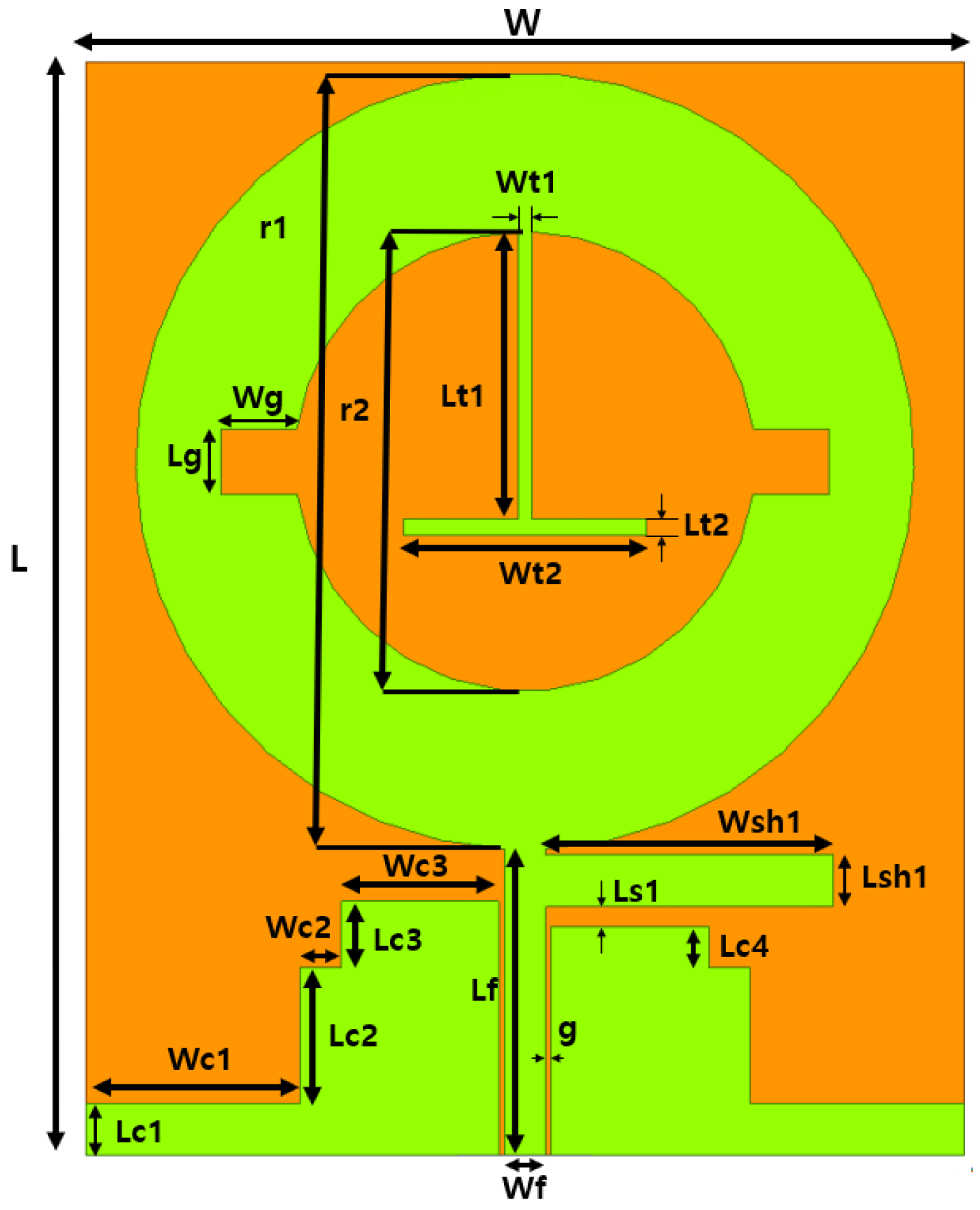
Figure 1. Proposed antenna structure.
Applsci 12 10717 g001
Figure 2. Step-by-step antenna design (a) antenna 1; (b) antenna 2; (c) antenna 3; (d) antenna 4; (e) antenna 5.
Applsci 12 10717 g002
Figure 3. S-parameter simulation for each step of the design.
Applsci 12 10717 g003
Figure 4. Current distribution of the proposed antenna; (a) current distribution at 2.4 GHz; (b) current distribution at 3.5 GHz; (c) current distribution at 7.5 GHz.
Applsci 12 10717 g004
Figure 5. S-parameter according to the size of r1.
Applsci 12 10717 g005
Figure 6. S-parameter according to the size of Wsh1.
Applsci 12 10717 g006
Figure 7. Photo of the antenna; (a) antenna without SMA connecter; (b) antenna with SMA connecter.
Applsci 12 10717 g007
Figure 8. Comparison of the antenna S-parameters between measurement and simulation.
Applsci 12 10717 g008
Figure 9. Comparison of the antenna VSWR between measurement and simulation.
Applsci 12 10717 g009
Figure 10. Simulated radiation efficiency of the proposed antenna.
Applsci 12 10717 g010
Figure 11. Simulated axial ratio of the proposed antenna.
Applsci 12 10717 g011
Figure 12. Comparison of the antenna 2D radiation pattern between measurement and simulation. (a) E-plane at 2.4 GHz; (b) H-plane at 2.4 GHz; (c) E-plane at 3.5 GHz; (d) H-plane at 3.5 GHz; (e) E-plane at 6.3 GHz; (f) H-plane at 6.3 GHz; (g) E-plane at 10 GHz; (h) H-plane at 10 GHz.
Applsci 12 10717 g012aApplsci 12 10717 g012b
Figure 13. Simulated antenna 3D radiation pattern of the proposed antenna; (a) 3D radiation pattern at 2.4 GHz; (b) 3D radiation pattern at 3.5 GHz; (c) 3D radiation pattern at 6.3 GHz; (d) 3D radiation pattern at 10 GHz.
Applsci 12 10717 g013aApplsci 12 10717 g013b
Figure 14. Gain of proposed antenna.
Applsci 12 10717 g014
Figure 15. Photo of the antenna when bent. (a) Antenna bent horizontally; (b) antenna bent vertically.
Applsci 12 10717 g015
Figure 16. Photo of the antenna bent using a styrofoam cylinder.
Applsci 12 10717 g016
Figure 17. S-parameter when the antenna is bent. (a) When bent horizontally, S-parameter according to the radius of the bend; (b) when bent vertically, S-parameter according to the radius of the bend.
Applsci 12 10717 g017aApplsci 12 10717 g017b
Table 1. Antenna parameters (unit: mm).
WLWt1Lt1Wt2Lt2
32400.510.58.90.6
WgLgr1r2Wsh1Lsh1
2.92.428.416.810.51.9
Lc1Lc2Lc3Lc4Wc1Wc2
1.952.41.57.81.5
Wc3Ls1WfLfg
5.750.71.511.20.2
Table 2. Parameter comparison with references.
Ref. No.Dimension
( m m 2 )
Bandwidth
(GHz)
Peak Gain
(dBi)
Application
[11] 34.9 × 48  
( 0.116 λ × 0.16 λ )
1–83.1UWB
[12] 71 × 98.35
( 0.568 λ × 0.787 λ )
2.4–2.45
5.15–7.1
6.855G/WLAN
[13] 20 × 32  
( 0.155 λ × 0.249 λ )
2.33–2.54
3.24–3.91
4.80–8.07
4.03WiMAX/WLAN/5G
[14] 32.6 × 52  
( 0.152 λ × 0.243 λ )
1.4–16.45.19UWB
[15] 40 × 50  
( 0.294 λ × 0.367 λ )
2.2–254.5UWB
[16] 40 × 55  
( 0.267 λ × 0.355 λ )
2–206.36UWB
[17] 36 × 30  
( 0.375 λ × 0.312 λ )
2.9–3.25
3.97–6.24
7.38–12
6.3WiMAX/UWB
Proposed antenna 32 × 40  
( 0.256 λ × 0.32 λ )
2.36~2.87
3.4~12
5.63WLAN/C-band/X-band
Publisher’s Note: MDPI stays neutral with regard to jurisdictional claims in published maps and institutional affiliations.