Abstract
In this paper, the scattered surface waves created by a surface crack in a homogeneous, isotropic, viscoelastic half space within a plane strain condition was studied. The amplitude of the scattered surface wave in the far field was determined by using the reciprocity theory and a virtual surface wave. It was shown that the amplitude of the scattered surface wave was related to the crack-opening displacement and the crack length. In the special case of low frequency and low viscosity, the tractions due to the incident surface wave applying on the crack surface can be regarded as uniform, and a finite element method (FEM) based on rubber material was performed to verify the theoretical results. It was shown that the numerical results were consistent with the theoretical solutions, which proves the reliability of the theoretical analysis. The reciprocity theorem avoids complex integral transformation and reveals the relationship between the scattered surface wave and the size of the surface crack, which is promising in the characterization of surface cracks.
1. Introduction
Rubber is a common engineering material, which plays a very important role in engineering construction and industrial production. Rubber material has many excellent properties; it can withstand a very large load without damage and can be completely recovered after the load disappears, so it is widely used in rubber bearings, buffers, bearings and other components [1]. However, when there are surface cracks on rubber, cracks under the action of fatigue load will endanger the integrity of the workpiece and may cause serious accidents [2,3]. Therefore, the detection of cracks is particularly important.
Ultrasonic nondestructive testing (NDT) has been extensively used in the detection of cracks because of the advantages of low cost, convenient operation and high detection accuracy. Ultrasounds consist of bulk waves (longitudinal wave, shear wave) and surface waves. Since the energy of the surface waves only distributes near the free surface, they are very sensitive to surface cracks. Therefore, many studies [4,5,6] have been devoted to the detection of surface cracks by using scattered surface waves.
For theoretical studies, with the development of computer technology, the finite element method (FEM) [7], boundary element method (BEM) [8,9] and several other advanced numerical methods [10,11] are widely used to study the scattering of surface waves caused by surface cracks. However, the common shortcoming of these numerical methods is that they cannot obtain accurate analytical solutions.
In order to obtain explicit expressions of ultrasonic waves, a better way is to formalize the relationship between crack and scattered waves based on wave mechanics. Bövik and Boström [12] solved the scattering elastic wave field of the subsurface strip crack by using the surface integral equation and the semi-infinite space Green’s function tensor, and calculated the far-field scattering wave field after the incident wave field emitted by the ultrasonic probe acted on the crack. Kang et al. [13] solved a new and validated model using a Gauss–Legendre quadrature, which provides an effective method for solving parametric relationships of wave scattering. This method avoids the acquisition of a large number of experimental data through theoretical deduction and has a reliable accuracy. Pecorari et al. [14] investigated the nonlinear scattering ultrasonic waves from surface-breaking cracks that were partially closed. It was found that when the vertical shear wave was incident on the surface crack at an angle slightly higher than the critical angle of the longitudinal wave, the nonlinear responses of the crack were maximum, and the second harmonic generation efficiency was the highest when the incident angle was close to the critical angle of the longitudinal wave. Nevertheless, these studies all needed to carry on the complicated separation variable and the integral transformation.
To simplify the calculation, a reciprocity theorem for the classical linear elastic condition has been proposed by Betti [15]. Then, Rayleigh [16] gave a more general theorem for the case of the elastodynamic problem. Although the reciprocity theorem has been proposed and studied for more than a century, it has not been widely used to actually solve elastodynamic problems. In recent years, Achenbach [17] proposed a simpler method based on the principle of the reciprocity theorem to actual calculate the wave fields. Kino [18] studied the scattering ultrasound from small flaws using the reciprocity theorem in Born approximation. Nevertheless, the flaws are not surface cracks. Phan et al. [19,20] used the reciprocity theorem to determine the solution of the surface waves generated by surface force sources under elastodynamic conditions, and they obtained a scattered surface wave by a surface cavity. Then, they used the reciprocity theorem to study the scattered wave fields of multiple surface cavities [21]. For surface crack, Achenbach [22] used the reciprocity theorem to determine the radiating surface wave by a surface-breaking crack, which was under uniform tensile stress composed of a constant and a superimposed cyclic tensile stress. However, for nondestructive detection using surface waves, there are normal stress and shear stress on the crack surface caused by incident surface waves due to the properties of surface wave [23]. Pecorari [24] used crack-opening displacement and reciprocity theory to explore the scattered Rayleigh wave by a surface-breaking crack, of which the faces were partially contacted. The work was modeled based on the quasi-static approximation and two different contact conditions were studied, whereas these studies were carried out on homogeneous, isotropic, linear elastic materials.
For studies of materials that are not linearly elastic, Mardanshahi et al. [25] proposed a model-independent viscoelastic characterization method to identify and classify the matrix cracking in polymeric composites based on the Lamb wave propagation method. Castaings et al. [26] evaluated complex wavenumbers of guided waves in viscoelastic materials using a numerical and asymptotic approach. Petia et al. [27] explored the propagation of elastic waves in a complex geological media, which was characterized by the inhomogeneity and transverse inhomogeneity of the material parameters varying with depth in the lateral direction. In these studies, either numerical methods were used or complex integrals were required. Using the simple reciprocity theory, Achenbach [28] determined the motion of a radiating surface wave with a time-harmonic point load, which was applied normally to the free surface of a material whose elastic moduli and mass density depended on the depth.
In this paper, the amplitudes of scattering surface waves caused by a vertical surface crack under normal and shear stresses of incident surface waves were calculated by using the elastic dynamic reciprocity theorem. The displacement integral was approximated when the crack length was sufficiently smaller than the wavelength of the incident surface wave and the viscosity of the material was low. For this special case, explicit analytical solutions were determined, and it was shown that the amplitudes of the scattered surface waves were dependent on the crack length and depth. Numerical calculations based on the finite element method were carried out to verify the theoretical analysis, and the two results were found to be in good agreement. It can be seen that using the reciprocity theorem is of great value in the crack scattering problem, which can avoid the complex integral transformation formula.
2. Incident Surface Wave and the Scattering Problem
2.1. Incident Surface Wave
When a wave propagates in a viscoelastic material, viscoelasticity will cause the dissipation of wave energy, which is manifested as wave attenuation and wave dispersion. In the uniform isotropic viscoelastic two-dimensional half plane defined by the x-z axis, the displacement field of the incident surface wave can be expressed as:
where and are the amplitude and frequency of the incident surface wave, respectively. is the time, and and represent the displacements in the x-axis and z-axis directions, respectively. Moreover, the positive and negative signs indicate that the propagation directions of the surface wave are the positive and negative directions of the x-axis, respectively. The time item is omitted to make the theoretical derivation convenient. For viscoelastic material, is the complex wave number, which can be calculated by , where is the complex phase velocity of the surface wave, which is the solution of the well-known Rayleigh wave phase velocity equation:
where and are the complex velocities of the longitudinal and shear waves, respectively, which can be written as:
where and are the complex parameters of the viscoelastic material. When the viscoelastic model is considered as the Kelvin–Voigt model, the complex parameters can be represented as:
where is the complex Young’s modulus, which can be written as:
where is the static Young’s modulus, and is the loss factor of Young’s modulus, which can be expressed as the ratio of imaginary parts to real parts of the complex Young’s modulus.
The functions and in Equation (1) are defined as follows:
where the parameters of are determined by the following formula:
where the parameters and can be calculated by the following equations:
The stress equation relative to Equation (1) is
where
and
2.2. Scattering Problem
There are body waves and surface waves in the scattered waves caused by surface cracks. However, it is known to us all that the surface wave energy usually dominates after a certain distance of propagation due to different geometric decays. In a two-dimensional half space, surface waves attenuate slowly, while the attenuation speed of body waves is , where r is the travel distance of the body waves. Therefore, only scattered surface waves are considered in this paper. It is worth mentioning that the following analysis is based on the assumption that the two surfaces of the surface-breaking crack do not interact with each other under the action of the ultrasonic field.
The model is regarded as a two-dimensional homogeneous, isotropic, linear viscoelastic half space with x-z as the coordinate axis, where the surface crack is on the boundary of the half space (z = 0); h is defined as the depth of the crack center, and l is the length of the crack, as shown in Figure 1.
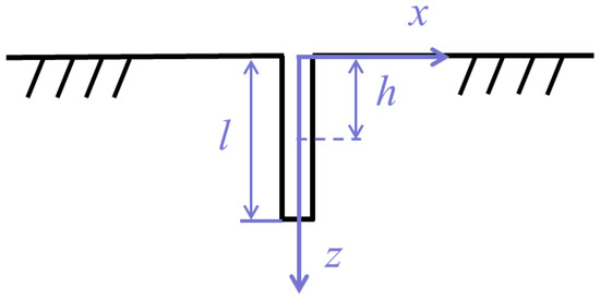
Figure 1.
Schematic diagram of a surface crack.
As shown in Figure 2, the incident surface wave propagates in the x positive direction along the free surface and interacts with the surface crack, producing forward- and backscattered surface waves. The total wave field during the interaction of the surface waves with the surface crack can be expressed as:
where is the total sound field, is the incident sound field, and is the scattered sound field. According to reference [23], the surface wave scattered by a crack can be equivalent to the radiated surface wave generated by the application of tractions ( and , as shown in Figure 2c) on the crack surface. The direction of the tractions shown in Figure 2c are opposite to the tractions ( and as shown in Figure 2b) that are generated by the incident surface wave at the virtual crack boundary. In addition, the magnitudes of and and and are equal, respectively.
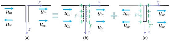
Figure 2.
Schematic diagram of scattering wave superposition principle of surface crack: (a) total field of incident wave and scattered wave; (b) incident wave field and its resultant tractions; (c) crack under tractions and corresponding scattered wave field.
3. Study on Scattered Surface Wave from Surface Crack Based on Reciprocity Theorem
3.1. Form of Scattered Surface Wave
The normal and shear stresses are loaded on the crack surface, and they jointly determine the amplitude of the scattered surface waves. Similar to the forms of the surface waves expressed in Section 2.1, the forward-scattered surface waves can be represented as:
The back-scattered surface waves can be represented as:
For the convenience of calculation, the time item is omitted. The superscript n and s in Equations (13)–(20) indicate normal stress and shear stress, respectively. The symbols “+” and “-” denote forward- and backscattered surface waves, respectively. In addition, and are the amplitude of the surface waves radiated by normal stress and shear stress, respectively. Since normal stresses are symmetric, it can be obtained that equals . For the antisymmetric shear stresses, it can be verified that equals .
3.2. Reciprocity Theorem for Solving the Amplitude of Scattered Surface Waves
In this section, the reciprocity theorem based on time-harmonic fields is employed to determine the amplitudes of the scattered surface waves. For the integral area of a body (V) and its surface (S), the reciprocity theorem can be expressed as:
where nj is the outer normal direction component of the surface S, and , and are the body force components, displacement components and stress components, respectively. The superscripts A and B represent the two results for the same object, respectively. In this problem, state A is the result of the scattered surface waves generated by the normal and shear stresses, and state B is the result of the scattered surface wave generated by a virtual wave at the crack. The virtual wave can be an acoustic wave of any mode. For the convenience of calculation, a virtual surface wave with the amplitude B was selected as state B in this paper, and the virtual surface wave propagates in the x positive direction along the free surface. The state B can be expressed as:
Since no body force exists in state A and B, , and Equation (21) can be simplified to:
For the integral contour of the body (S presented in Figure 3), let the integration of the line at be , and for , , the integration is represented as , while the integration on the two crack surfaces are called and , respectively. The integrations along the free surface and the bottom of the contour are called , and , respectively. The integration far away from the free surface is called , since the energy of the surface waves exists within twice the wavelength depth, . For the integration on the free surface, that is and , the results are also zero since the traction on the free boundary is zero. In the previous study [20], it has been verified that integrations are not zero only when the two waves are counter-propagating waves. In this paper, states A and B are counter-propagating waves at , . Hence, we have . Therefore, the contour integral reduces to:
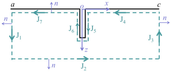
Figure 3.
Body and contour of surface crack for the application of reciprocity theorem.
For J1, the substitution of ,,, (represented in Equations (17) and (18)), ,,, (represented in Equations (19) and (20)) and ,,, (represented in Equations (22) and (23)) into Equation (24) yields:
The superscript n and s of the integral J1 represent the scattered surface waves generated by normal stresses and shear stress, respectively, and I is written as follows:
It should be noted that I can be determined by Equations (6) and (10); thus, it can be written as:
where
and is dimensionless.
Next, the contributions from the integration along J5 and J6 are considered. For the normal stresses condition, we have:
where
For the normal stresses, the crack opens up symmetrically, so we have ,. As a consequence, only the first term in Equation (31) remains, and reduces to:
Similarly, the crack opens up anti-symmetrically under the shear stresses, so we have ,,, . Thus, for shear stresses, Equation (32) changes to:
where and are the CODs in the x and z directions, respectively. The superscript and mean that the CODs are generated by normal and shear traction on the surface crack, respectively. Since the total contour integral is zero as expressed in Equation (25), the amplitudes and can be solved by Equations (25), (26), (32) and (33), which are finally simplified as follows:
It is worth mentioning that the CODs and are, as yet, unknown. The crack-opening displacement will be obtained numerically in the next section.
4. Special Case of Low Frequency and Low Viscosity
When the frequency of the incident surface wave is low and the ratio of the crack length to wavelength of the incident surface wave is sufficiently small, the normal and shear tractions generated by the incident surface wave can be considered to be uniformly distributed on the crack surface. In addition, for low-frequency waves, wave dispersion can be neglected when the viscosity is small, that is, the phase velocity of sound waves remains unchanged during propagation. Thus, for the simplicity of verification, the crack length was set to be sufficiently smaller than the wavelength of the incident surface wave. Thus, the tractions on the crack surface can be expressed by the stresses at the center of the crack, which are as follows:
where is the distance between the origin of the incident surface wave and the surface crack. In the special case,
For the special case of low frequency and low viscosity, a numerical calculation was carried out to verify the analytical results. The numerical simulation was solved by the commercial software ABAQUS. In the simulations, the material was rubber, of which the density and Poisson’s ratio were 1140 and 0.49, respectively. When the frequency of the surface wave is 5 kHz, the parameters and Young’s modulus can be determined by Equations (6) and (7). Then, the corresponding velocities of the longitudinal wave, shear wave and surface wave can be determined based on Equations (4)–(7), which were 810 m/s, 100 m/s and 95 m/s, respectively. Thus, the corresponding wavelength () was 5.8 mm. In order to make the wavelength of the incident surface wave sufficiently larger than the crack length, the crack lengths () were between 100 and 2000 with a step of 400 . It should be noted that the crack shape was rectangular in the numerical model, and the width of the crack was set to be 10 μm. The ratio of the crack length to width was greater than 10, which meant the rectangular-shaped defect could be used to simulate crack.
For the plane strain condition, the numerical simulation can be modeled in a two-dimensional plane, which would save a lot of calculation time of the model. In order to minimize the influence of the reflected waves from model boundaries, and to reduce the size and running time of the simulation model, absorbing boundaries were applied to the left and right sides and the bottom of the model. The free surface of the model adopted free boundary conditions, and the initial displacement field was zero. In order to accurately solve the wave propagation problems and track the generation process of the scattering surface wave from the crack, a small time step and element size were needed. In general, to solve wave propagation problems, the element size should be smaller than 1/20 of the wavelength to obtain better spatial resolution of the wave propagation, and the time step should be smaller than 1/20 of the reciprocal of the wave frequency, namely:
where is the time step of the numerical calculation, is the element size, and and are the frequency and wavelength ultrasonic wave, respectively. It is worth noting that in the simulation model, the element size in the region around the crack should be equal to the crack width to accurately simulate the wave propagation in the region around the crack. Thus, the element size was 10 μm near the crack, and gradually increased to 200 μm in the far field, and the time step of calculation was 2 ns.
The amplitude of the incident surface wave was set as 10 nm, which was . The central depth of the surface crack was . Thus, the stresses of , and could be obtained according to Equations (9)–(11), and the ratio of stresses to at depth of zero () is shown in Figure 4. The trend of the curves was consistent with that of the surface wave stress curve of linear elastic material, as shown in Figure 4. In addition, the three stresses all increased first and then decreased, and at the depth of twice the wavelength of the surface wave, the stress decreased to almost zero. Furthermore, the directions of stresses and remained the same, but the direction of stress changed from positive to negative at a certain depth.
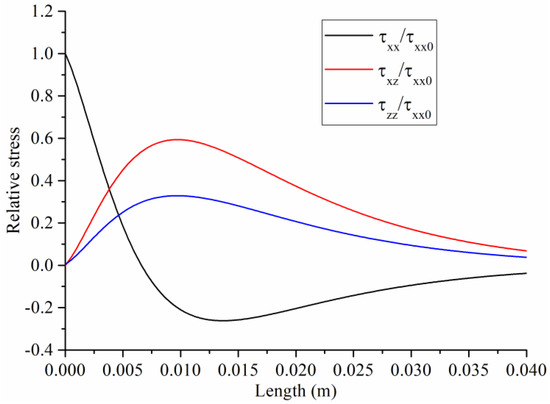
Figure 4.
Stress amplitudes as function of depth.
The tractions at the center of the cracks with different length can be calculated using Equation (35), and the results are shown in Table 1. Then, the uniform tractions shown in Table 1 were applied to the crack surface in the numerical models; the corresponding crack-opening displacement along the surface of different cracks was obtained, and the results are shown in Figure 5. It can be seen that the CODs at the same depth increased with the increase in crack length due to the increase in the normal and shear tractions. However, for a certain crack length, the COD decreased with the increase in the crack depth since the two crack surfaces connected with each other at the bottom of the crack, which made the crack surface hard to open. The farther away from the bottom of the crack, the easier it was to open and the larger the crack-opening displacement was. In addition, the maximum crack-opening displacement was several nanometers, which was sufficiently smaller than the crack width in the model, so the two surfaces of the crack did not interact with each other. It was consistent with the hypothesis of the study in the paper. It should be noted that theoretical solution of the crack-opening displacement should be determined to obtain more accurate results, since the shape of the crack in the numerical model is rectangular, which is slightly different from the real crack.

Table 1.
Magnitudes of normal and shear tractions on crack surface.
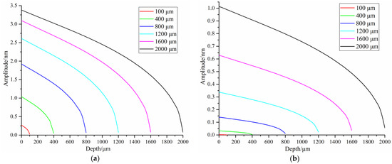
Figure 5.
Crack-opening displacement produced by: (a) normal stress; (b) shear stress.
For the simplicity of computation, the Newton–Coates formula was used to approximate the average COD (represented as and ) of the crack, and then the theoretical amplitudes of the scattering surface waves by cracks can be represented as:
By substituting Equation (38) into Equations (17) and (19), the theoretical expressions of the displacements of back-scattered surface waves in x and z directions can be determined as follows:
It is worth noting that the forward-scattered surface waves can be evaluated by selecting a virtual surface wave that propagates in the x-negative direction.
To verify the theoretical results, numerical amplitudes of the scattered surface wave were calculated by applying the uniform tractions (shown in Table 1) with a frequency of 5 kHz on the crack surface in the finite element models. The amplitudes of the scattered surface waves in x and z direction were detected at the free surface of the model, where mm. The numerical and theoretical results are compared in Figure 6. The theoretical results are in good agreement with the numerical results, as shown in Figure 6. In addition, with the increase in crack length, the amplitude of the scattered surface wave increased and the error between the numerical and analytical results increased. The special case of low frequency and low viscosity proved that the reciprocity theorem, together with the virtual wave technique, is feasible to determine the amplitude of the scattered surface wave of viscoelastic materials.
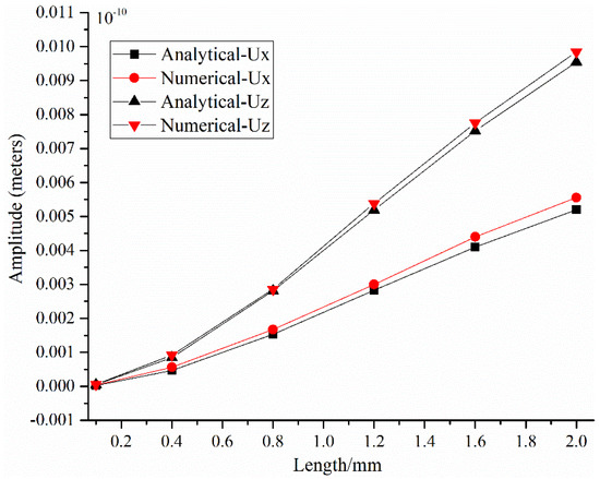
Figure 6.
Comparison diagram of theoretical and simulation amplitudes.
5. Conclusions
In this study, the amplitudes of scattered surface waves by a surface crack in a homogeneous, isotropic, viscoelastic material with a plane strain condition was evaluated based on the elastic reciprocity theorem and virtual wave technique. It was shown that the amplitudes of scattered surface waves were the function of COD and crack length, and the COD was related to the crack depth. For the special case of low frequency and low viscosity, the finite element method (FEM) was used to verify the theoretical analysis, and good agreement was achieved. It can be concluded that the reciprocity theorem and the virtual wave technique can provide a very effective way to theoretically derive scattering surface waves from surface cracks. In addition, the method can avoid complex integral transformations and is promising in the quantitative characterization of surface cracks in viscoelastic material. In future work, scattering surface waves from partially closed surface-breaking cracks will be studied. The wire cutting method will be used to manufacture these cracks in rubbers, and experimental studies will be carried out to study nondestructive testing approaches with acoustic methods of real rubbers.
Author Contributions
Conceptualization, L.Z. and C.W.; Investigation, A.S.; Methodology, L.Z.; Project administration, J.L.; Supervision, J.L.; Validation, C.W.; Visualization, A.S.; Writing—original draft, L.Z.; Writing—review & editing, C.W. All authors have read and agreed to the published version of the manuscript.
Funding
This research was funded by National Natural Science Foundation of China, grant Number 51905479 and 52175521), and Fundamental Research Funds for the Provincial Universities of Zhejiang, grant Number GK219909299001-020. The APC was funded by 51905479.
Institutional Review Board Statement
The study did not require ethical approval.
Informed Consent Statement
Not applicable.
Conflicts of Interest
The authors declare no conflict of interest.
References
- Samaržija-Jovanović, S.; Jovanović, V.; Marković, G.; Konstantinović, S.; Marinović-Cincović, M. Nanocomposites based on silica-reinforced ethylene–propylene–diene–monomer/acrylonitrile–butadiene rubber blends. Compos. B. Eng. 2011, 42, 1244–1250. [Google Scholar] [CrossRef]
- Noethen, M.; Jia, Y.; Meyendorf, N. Simulation of the surface crack detection using inductive heated thermography. Nondestruct. Test. Eval. 2012, 27, 139–149. [Google Scholar] [CrossRef]
- Hu, B.; Liu, Y.; Yu, R. Magnetic anomaly characteristics of surface crack defects in a titanium alloy plate. Nondestruct. Test. Eval. 2020, 36, 209–224. [Google Scholar] [CrossRef]
- Hirao, M.; Fukuoka, H.; Miura, Y. Scattering of Rayleigh surface waves by edge cracks: Numerical simulation and experiment. J. Acoust. Soc. Am. 1982, 72, 602–606. [Google Scholar] [CrossRef]
- Cook, D.A.; Berthelot, Y.H. Detection of small surface-breaking fatigue cracks in steel using scattering of Rayleigh waves. NDT E Int. 2001, 34, 483–492. [Google Scholar] [CrossRef]
- Kim, J.Y.; Rokhlin, S.I. Surface acoustic wave measurements of small fatigue cracks initiated from a surface cavity. Int. J. Solids Struct. 2002, 39, 1487–1504. [Google Scholar] [CrossRef]
- Hassan, W.; Veronesi, W. Finite element analysis of Rayleigh wave interaction with finite-size, surface-breaking cracks. Ultrasonics 2003, 41, 41–52. [Google Scholar] [CrossRef]
- Arias, I.; Achenbach, J.D. Rayleigh wave correction for the BEM analysis of two-dimensional elastodynamic problems in a half-space. Int. J. Numer. Methods Eng. 2004, 60, 2131–2146. [Google Scholar] [CrossRef]
- Liu, W.; Cho, Y.; Phan, H.; Achenbach, J.D. Study on the scattering of 2-D Rayleigh waves by a cavity based on BEM simulation. J. Mech. Sci. Technol. 2011, 25, 797–802. [Google Scholar] [CrossRef]
- Golub, M.V.; Fomenko, S.I.; Bui, T.Q.; Zhang, C.; Wang, Y.S. Transmission and band gaps of elastic SH waves in functionally graded periodic laminates. Int. J. Solids Struct. 2012, 49, 344–354. [Google Scholar] [CrossRef]
- Hedayatrasa, S.; Bui, T.Q.; Zhang, C.; Lim, C.W. Numerical modeling of wave propagation in functionally graded materials using time-domain spectral Chebyshev elements. J. Comput. Phys. 2014, 258, 381–404. [Google Scholar] [CrossRef]
- Bövik, P.; Boström, A. A model of ultrasonic nondestructive testing for internal and subsurface cracks. J. Acoust. Soc. Am. 1997, 102, 2723–2733. [Google Scholar] [CrossRef]
- Kang, S.; Wu, Y.C.; Ham, S. Singular Integral Solutions of Analytical Surface Wave Model with Internal Crack. Appl. Sci. 2020, 10, 3129. [Google Scholar] [CrossRef]
- Pecorari, C.; Poznić, M. Nonlinear acoustic scattering by a partially closed surface-breaking crack. J. Acoust. Soc. Am. 2005, 117, 592–600. [Google Scholar] [CrossRef] [PubMed]
- Betti, E. Teoria della elasticita. Il Nuovo Cim. 1872, 7, 158–180. [Google Scholar] [CrossRef]
- Rayleigh, L. Some General Theorems Relating to Vibrations. Proc. London Math. Soc. 1873, 4, 357–368. [Google Scholar]
- Achenbach, J.D. Reciprocity in Elastodynamics; Cambridge University Press: Cambridge, UK, 2004. [Google Scholar]
- Kino, G.S. The application of reciprocity theory to scattering of acoustic waves by flaws. J. Appl. Phys. 1978, 49, 3190–3199. [Google Scholar] [CrossRef]
- Phan, H.; Cho, Y.; Achenbach, J.D. Verification of surface wave solutions obtained by the reciprocity theorem. Ultrasonics 2014, 54, 1891–1894. [Google Scholar] [CrossRef]
- Phan, H.; Cho, Y.; Achenbach, J.D. Application of the reciprocity theorem to scattering of surface waves by a cavity. Int. J. Solids Struct. 2013, 50, 4080–4088. [Google Scholar] [CrossRef]
- Phan, H.; Cho, Y.; Li, W. A theoretical approach to multiple scattering of surface waves by shallow cavities in a half-space. Ultrasonics 2018, 88, 16–25. [Google Scholar] [CrossRef]
- Achenbach, J.D. Acoustic emission from a surface-breaking crack under cyclic loading. Acta Mech. 2008, 195, 61–68. [Google Scholar] [CrossRef]
- Chao, Y.; Achenbach, J.D. Radiation from Equivalent Body Forces for Scattering of Surface Waves by a Near-Surface Cylindrical Cavity. In Generalized Models and Non-classical Approaches in Complex Materials 2; Springer: Cham, Switzerland, 2018. [Google Scholar]
- Pecorari, C. Scattering of a Rayleigh wave by a surface-breaking crack with faces in partial contact. Wave Motion 2001, 33, 259–270. [Google Scholar] [CrossRef]
- Mardanshahi, A.; Shokrieh, M.M.; Kazemirad, S. Identification of matrix cracking in cross-ply laminated composites using Lamb wave propagation. Compos. Struct. 2020, 235, 111790. [Google Scholar] [CrossRef]
- Zakharov, D.; Castaings, M.; Singh, D. Numerical and asymptotic approach for evaluating complex wavenumbers of guided modes in viscoelastic plates. J. Acoust. Soc. Am. 2011, 130, 764–771. [Google Scholar] [CrossRef] [PubMed]
- Dineva, P.S.; Wuttke, F.; Manolis, G.D. Elastic wave scattering and stress concentration effects in non-homogeneous poroelastic geological media with discontinuities. Soil Dyn. Earthq. Eng. 2012, 41, 102–118. [Google Scholar] [CrossRef]
- Achenbach, J.D. A new use of the elastodynamic reciprocity theorem. Math Mech. Solids 2014, 19, 5–18. [Google Scholar] [CrossRef]


Publisher’s Note: MDPI stays neutral with regard to jurisdictional claims in published maps and institutional affiliations. |
© 2022 by the authors. Licensee MDPI, Basel, Switzerland. This article is an open access article distributed under the terms and conditions of the Creative Commons Attribution (CC BY) license (https://creativecommons.org/licenses/by/4.0/).