
A Novel Method for Testing the Effect of Base Post-Grouting of Super-Long Piles

Abstract
:1. Introduction
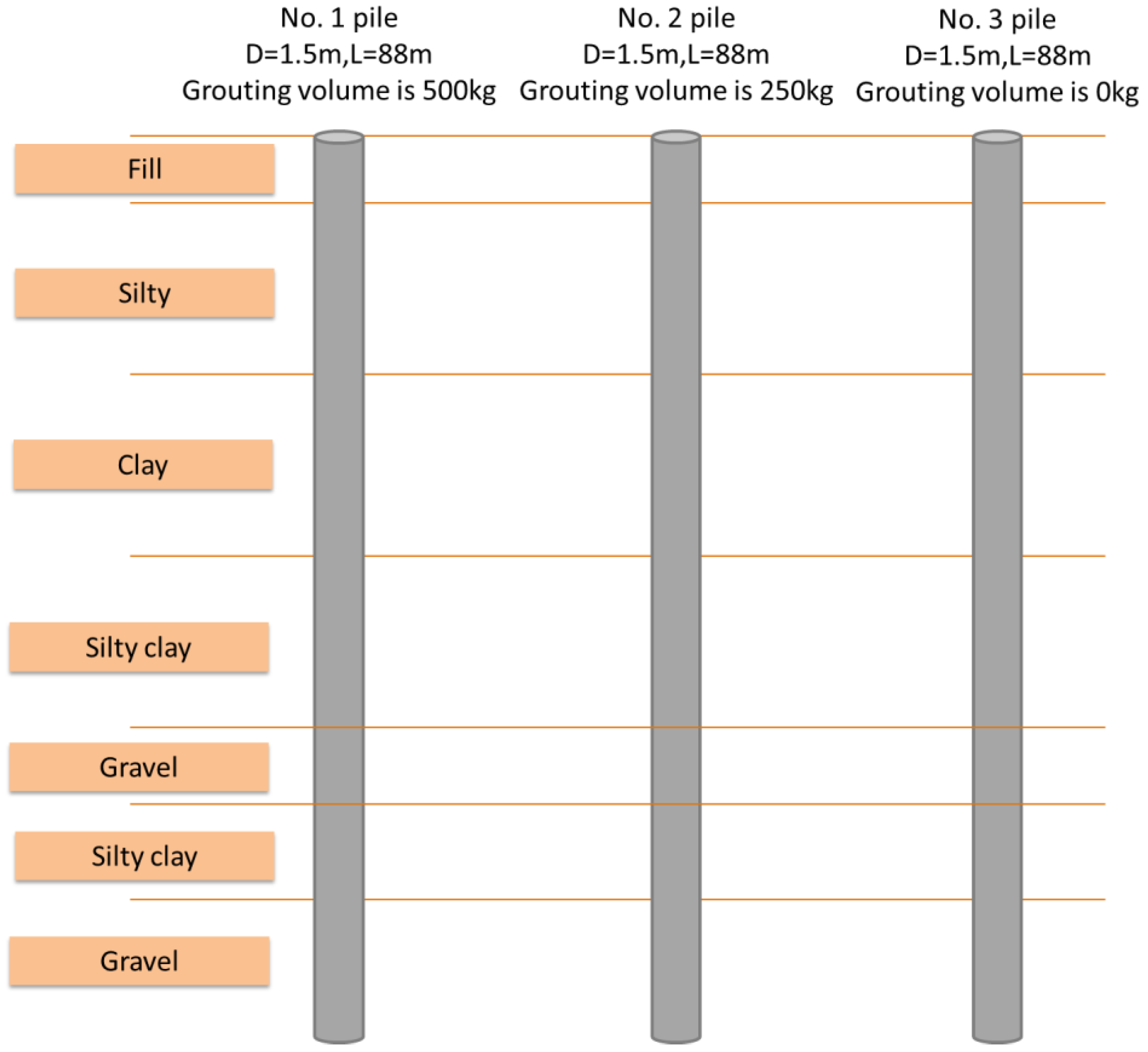
2. Project Overview
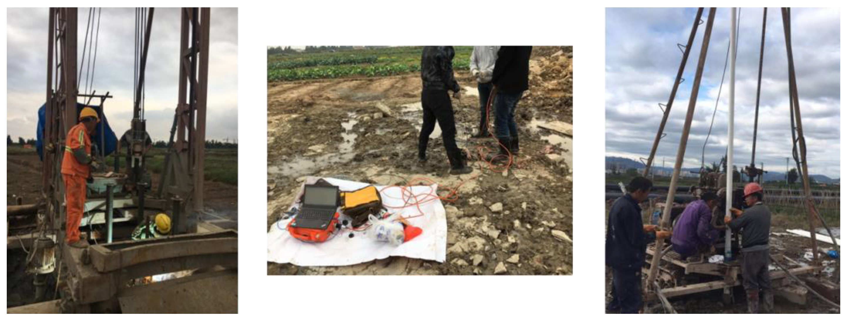
3. Methodology
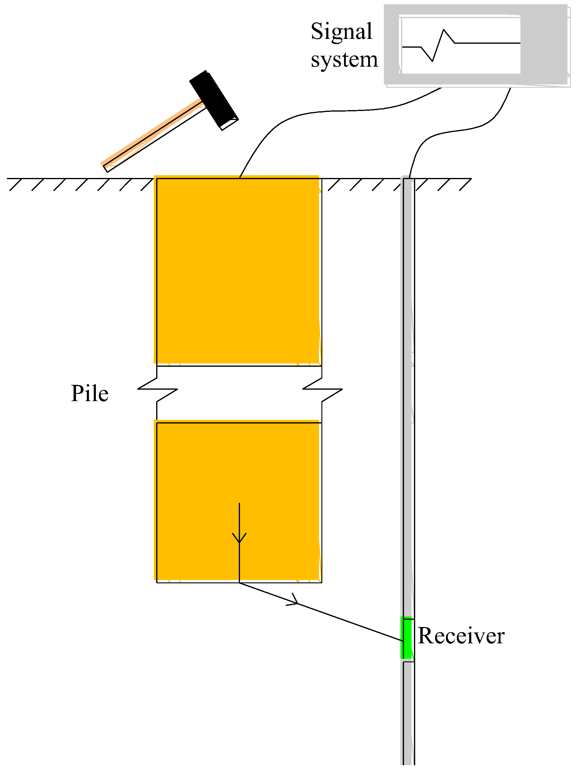
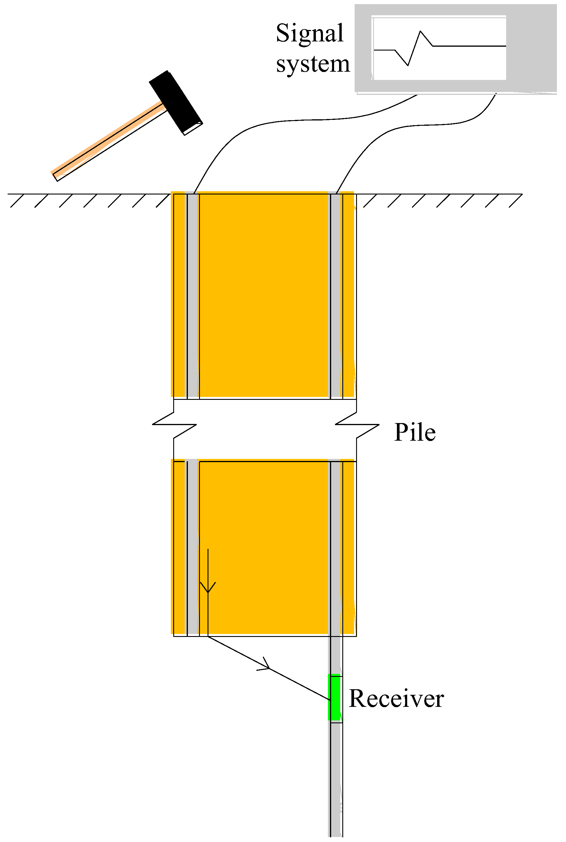
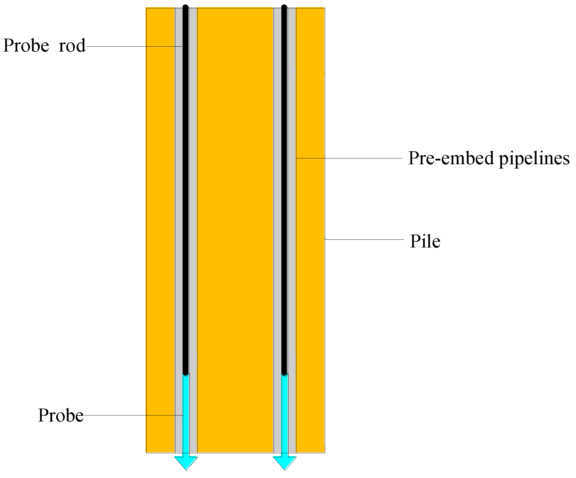
3.1. Test of Transmitted Wave in the Pile
3.2. Test of Dynamic Penetration
4. Results
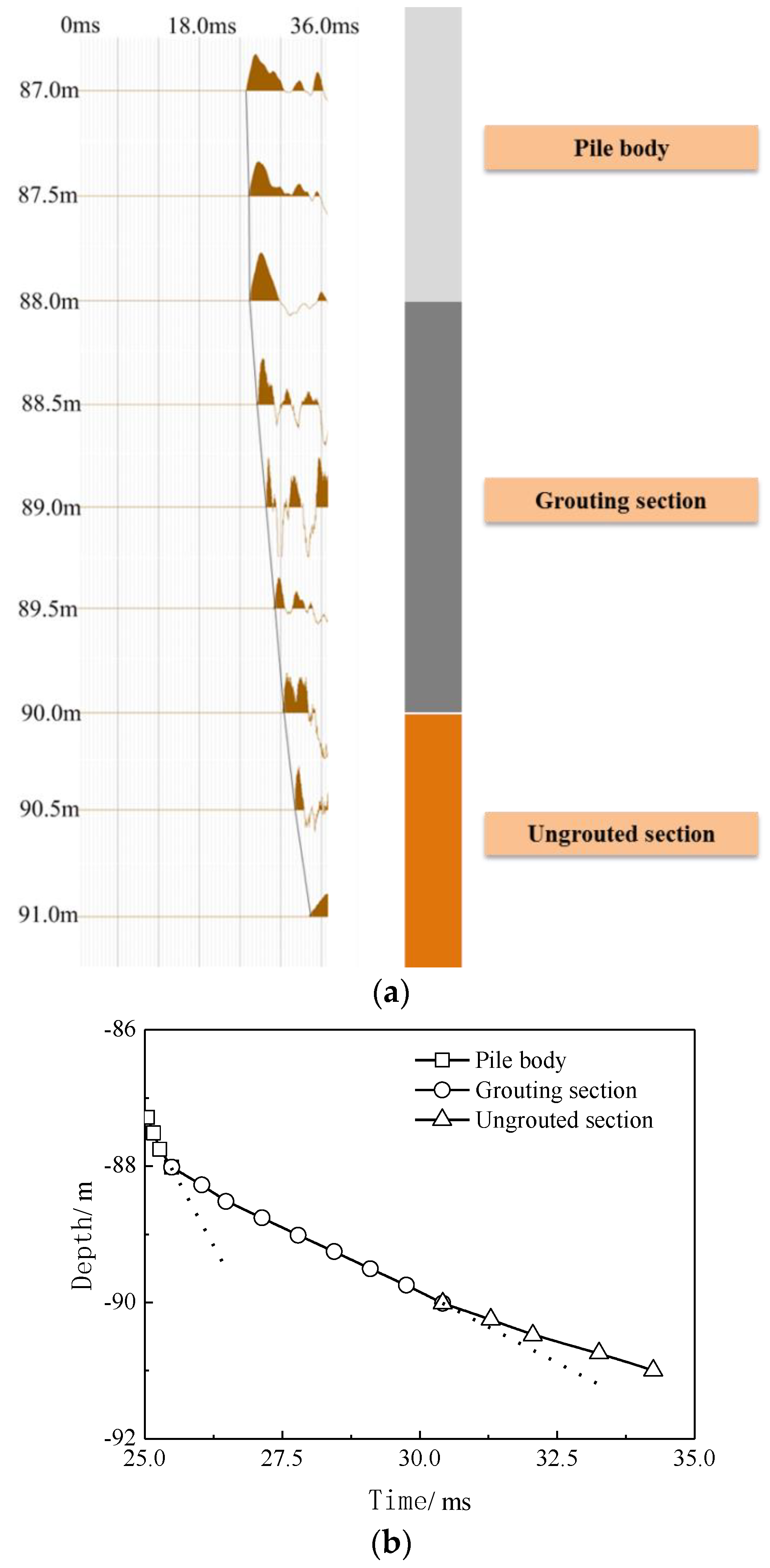
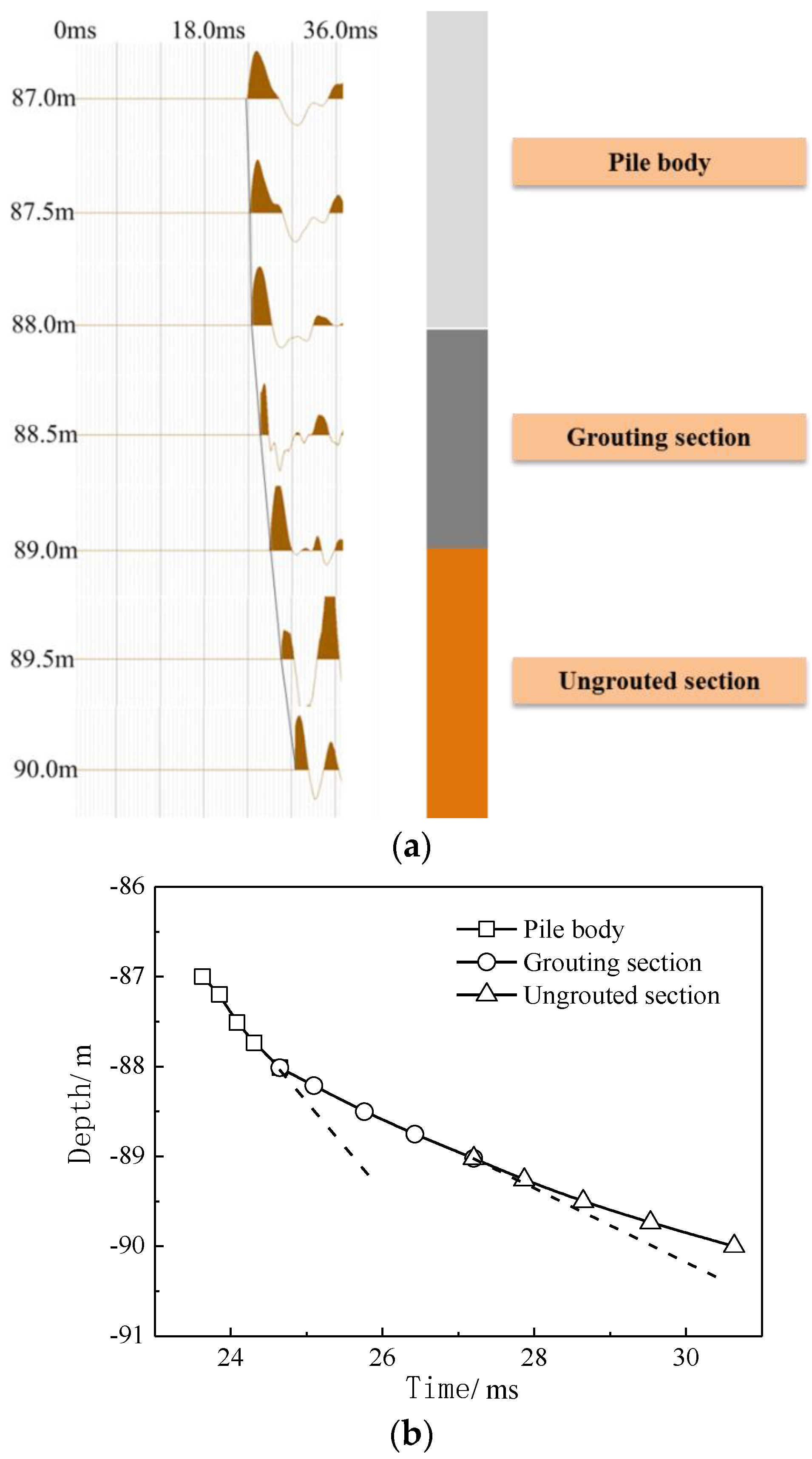
4.1. Test Analysis of Transmitted Wave in the Pile
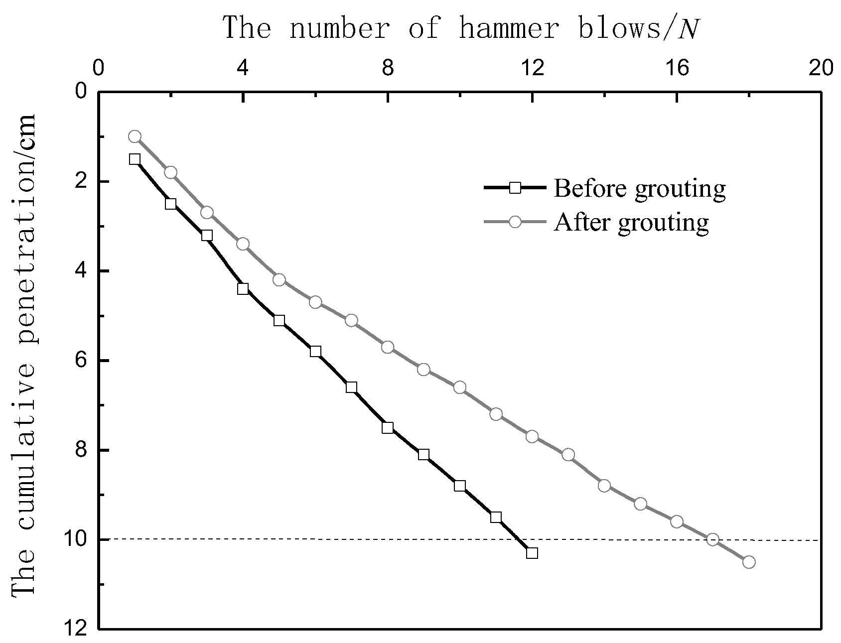
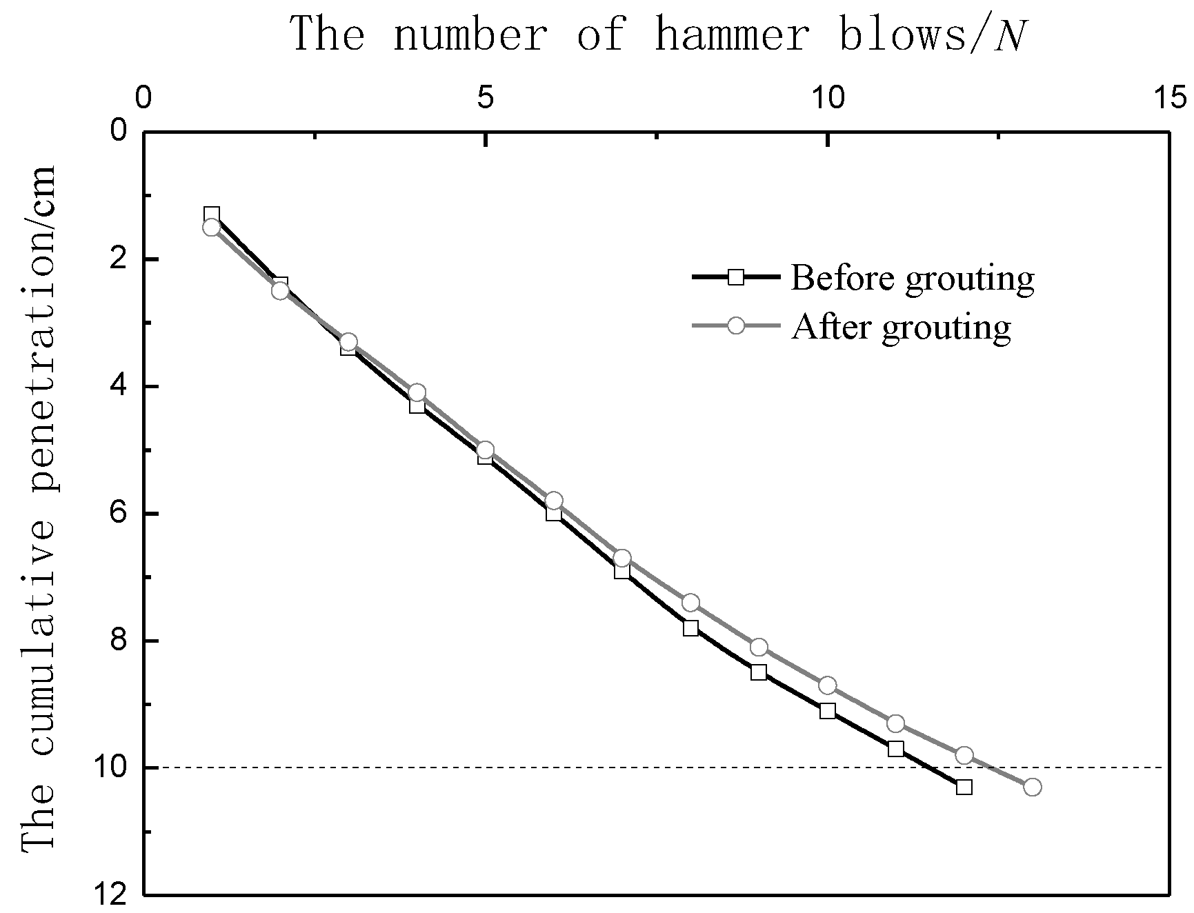
4.2. Test Analysis of Dynamic Penetration
5. Discussion
6. Conclusions
- (1)
- The influencing range of base post-grouting was firstly evaluated by the transmitted wave method in the pile. The depth of the pile base reinforcement was 2 m for No. 1 pile, and 1 m for No. 2 pile, which was consistent with the grouting amount.
- (2)
- The strength of the soil before and after grouting under the same pile base was measured by the dynamic penetration method. The elastic modulus of the base soil after post-grouting was about twice that of the base soil before grouting.
- (3)
- The properties of the base soil increased with the grouting amount. The bearing capacity of the base soil layer increased from 35.5% to 41.7%, as the grouting amount increased from 250 kg to 500 kg.
Author Contributions
Funding
Institutional Review Board Statement
Informed Consent Statement
Conflicts of Interest
References
- Ng, C.W.; Zhang, L.; Nip, D.C. Response of laterally loaded large-diameter bored pile groups. J. Geotech. Geoenvironmental Eng. 2001, 127, 658–669. [Google Scholar] [CrossRef]
- Brown, M.J.; Hyde, A.; Anderson, W. Analysis of a rapid load test on an instrumented bored pile in clay. Geotechnique 2006, 56, 627–638. [Google Scholar] [CrossRef] [Green Version]
- Moayedi, H.; Hayati, S. Applicability of a cpt-based neural network solution in predicting load-settlement responses of bored pile. Int. J. Geomech. 2018, 18, 06018009. [Google Scholar] [CrossRef]
- Zhang, Q.; Feng, R.; Yu, Y.; Liu, S.; Qian, J. Simplified approach for prediction of nonlinear response of bored pile embedded in sand. Soils Found. 2019, 59, 1562–1578. [Google Scholar] [CrossRef]
- Zhou, J.; Yu, J.; Gong, X.; El Naggar, M.H.; Zhang, R. Field study on the behavior of pre-bored grouted planted pile with enlarged grout base. Acta Geotech. 2021, 16, 3327–3338. [Google Scholar] [CrossRef]
- Safaqah, O.; Bittner, R.; Zhang, X. Post-Grouting of Drilled Shaft Tips on the Sutong Bridge: A Case History. Geo-Denver 2007, 1–10. [Google Scholar]
- Bruce, D. Enhancing the performance of large diameter piles by grouting. Ground Eng. 1986, 19, 9–15. [Google Scholar]
- Aurora, R.; Reese, L. Behavior of axially loaded drilled shafts in clay-shales. Design Methods 1976, 172p. Available online: https://trid.trb.org/view.aspx?id=62914 (accessed on 19 September 2022).
- Zhang, Z.; Yu, J.; Zhang, G.; Zhou, X. Test study on the characteristics of mudcakes and in situ soils around bored piles. Can. Geotech. J. 2009, 46, 241–255. [Google Scholar] [CrossRef]
- Hirayama, H. Load-settlement analysis for bored piles using hyperbolic transfer functions. Soils Found. 1990, 30, 55–64. [Google Scholar] [CrossRef] [Green Version]
- Mullins, G.; Winters, D.; Dapp, S. Predicting end bearing capacity of post-grouted drilled shaft in cohesionless soils. J. Geotech. Geoenvironmental Eng. 2006, 132, 478–487. [Google Scholar] [CrossRef] [Green Version]
- Mullins, G.; Dapp, S.; Frederick, E.; Wagner, R. Post Grouting Drilled Shaft Tips. Phase I (no. Final Report); Submitted Florida Department of Transportation: Tallahassee, FL, USA, 2001. [Google Scholar]
- Dai, G.; Gong, W.; Zhao, X.; Zhou, X. Static testing of pile-base post-grouting piles of the suramadu bridge. Geotech. Test. J. 2011, 34, 34–49. [Google Scholar]
- Fang, K.; Zhang, Z.; Zou, J.; Wang, Z. Laboratory studies on pressure filtration in post-grouting of drilled shaft tips in clay. Geotech. Test. J. 2012, 35, 665–671. [Google Scholar] [CrossRef]
- Khazaei, J.; Eslami, A. Postgrouted helical piles behavior through physical modeling by fcv. Mar. Georesources Geotechnol. 2017, 35, 528–537. [Google Scholar] [CrossRef]
- Wan, Z.; Dai, G.; Gong, W. Field study on post-grouting effects of cast-in-place bored piles in extra-thick fine sand layers. Acta Geotech. 2019, 14, 1357–1377. [Google Scholar] [CrossRef]
- Zhou, Z.; Xu, F.; Lei, J.; Bai, Y.; Chen, C.; Xu, T.; Zhang, Z.; Zhu, L.; Liu, T. Experimental study of the influence of different hole-forming methods on the bearing characteristics of post-grouting pile in loess areas. Transp. Geotech. 2021, 27, 100423. [Google Scholar] [CrossRef]
- Yao, W.; Qiu, Y.; Chen, Z. Ultimate bearing capacity analysis of a super-long rock-socketed filling pile based on catastrophe theory. Adv. Struct. Eng. 2010, 13, 331–338. [Google Scholar] [CrossRef]
- Feng, S.; Lu, S.; Shi, Z. Field investigations of two super-long steel pipe piles in offshore areas. Mar. Georesources Geotechnol. 2016, 34, 559–570. [Google Scholar] [CrossRef]
- Davis, A.G. Nondestructive evaluation of existing deep foundations. J. Perform. Constr. Facil. 1995, 9, 57–74. [Google Scholar] [CrossRef]
- Pinjarkar, S.G.; Kritzler, R.W.; Rolsing, R.A.; Mccarthy, P.O. Evaluation and load testing of a 100-year-old elevated steel transit structure. Transp. Res. Record 1991, 1290, 252–256. [Google Scholar]
- Zhu, J.; Yin, K.; Gong, W.; Xie, F. Discussion about several issues of bi-directional load testing in Chinese, American and European standards. Rock Soil Mech. 2020, 10, 3491–3499. (In Chinese) [Google Scholar]
- Coyle, H.M.; Bartoskewitz, R.E. Prediction of shear strength of sand by use of dynamic penetration tests. Transp. Res. Rec. 1980, 749, 46–54. [Google Scholar]
- Lin, L.; Li, S.; Sun, L.; Liu, X.; Chen, W. Study of relative compaction for calcareous sand soil using dynamic cone penetration test. Rock Soil Mech. 2020, 08, 2730–2738. (In Chinese) [Google Scholar]
- Liu, X.; Jie, X.; You, X.; Xie, F. Study on bearing behavior of large diameter driven steel pipe pile in coral reef geology. Ocean. Eng. 2019, 37, 157–163. [Google Scholar]
- Li, H.; Guo, F.; Fu, S.; Hao, W.; Li, Z. Adaptation and correction of dynamic penetration rod length. Earth Sci. 2016, 41, 1249–1258. (In Chinese) [Google Scholar]
- Wen, X. The Research of Heavy dynamic Sounding Rod Length Correction Issue. Shenyang Jianzhu Univ. 2015. (In Chinese) [Google Scholar]


| Layer Number | Formation Name | H/m | γ/(kN·m−3) | ES/(MPa) | c/(kPa) | φ/(°) | fa/(kPa) |
|---|---|---|---|---|---|---|---|
| 1 | Fill | 2.1 | |||||
| 2 | Silt | 19.4 | 16.5 | 2.16 | 8.9 | 2.8 | 55 |
| 3 | Clay | 23.8 | 17.6 | 3.06 | 20.3 | 5.4 | 80 |
| 4 | Silty clay | 26.1 | 18.1 | 4.09 | 31.3 | 7.6 | 120 |
| 5 | Gravel | 2.9 | 200 | ||||
| 6 | Silty clay | 10.9 | 18.9 | 4.45 | 41.1 | 9.4 | 180 |
| 7 | Gravel | 18.1 | 200 |
| Hammer Quality (kg) | Drop Distance (cm) | Probe Diameter (mm) | Probe Cone Angle (°) | Probe Rod Diameter (mm) | Target Penetration Depth (cm) |
|---|---|---|---|---|---|
| 10 | 76 | 74 | 60 | 42 | 10 |
| Hammering Times | 3 | 4 | 5 | 6 | 8 | 10 | 12 |
|---|---|---|---|---|---|---|---|
| Characteristic value of foundation bearing capacity (kPa) | 140 | 170 | 200 | 240 | 320 | 400 | 480 |
| Characteristic Value of Foundation Bearing Capacity (kPa) | Before Grouting | After Grouting |
|---|---|---|
| No. 1 pile | 211.2 | 299.2 |
| No. 2 pile | 168.8 | 228.8 |
| No. 3 pile | 211.2 | 211.2 |
Publisher’s Note: MDPI stays neutral with regard to jurisdictional claims in published maps and institutional affiliations. |
© 2022 by the authors. Licensee MDPI, Basel, Switzerland. This article is an open access article distributed under the terms and conditions of the Creative Commons Attribution (CC BY) license (https://creativecommons.org/licenses/by/4.0/).
Share and Cite
Hu, H.; Jin, Q.; Yang, F.; Zhou, J.; Ma, J.; Gong, X.; Guo, J. A Novel Method for Testing the Effect of Base Post-Grouting of Super-Long Piles. Appl. Sci. 2022, 12, 10996. https://doi.org/10.3390/app122110996
Hu H, Jin Q, Yang F, Zhou J, Ma J, Gong X, Guo J. A Novel Method for Testing the Effect of Base Post-Grouting of Super-Long Piles. Applied Sciences. 2022; 12(21):10996. https://doi.org/10.3390/app122110996
Chicago/Turabian StyleHu, Haibo, Qiqin Jin, Feng Yang, Jiajin Zhou, Junjie Ma, Xiaonan Gong, and Jin Guo. 2022. "A Novel Method for Testing the Effect of Base Post-Grouting of Super-Long Piles" Applied Sciences 12, no. 21: 10996. https://doi.org/10.3390/app122110996