Article

A Novel Method for Testing the Effect of Base Post-Grouting of Super-Long Piles

1
Research Center of Coastal and Urban Geotechnical Engineering, Zhejiang University, Hangzhou 310058, China
2
Engineering Research Center of Urban Underground Development of Zhejiang Province, Hangzhou 310058, China
3
China Railway Tunnel Group Municipal Engineering Company, Hangzhou 310030, China
*
Author to whom correspondence should be addressed.
Appl. Sci. 2022, 12(21), 10996; https://doi.org/10.3390/app122110996
Submission received: 20 September 2022 / Revised: 24 October 2022 / Accepted: 27 October 2022 / Published: 30 October 2022
(This article belongs to the Section Civil Engineering)

Abstract

:
The base post-grouting technology is widely used in pile foundation engineering to improve its behavior. For super-long piles, due to the large compression of pile shaft, conventional static load tests cannot effectively test the effect of post-grouting at the pile base. This study introduced a novel method to test the effect of base post-grouting of three 88 m long piles. A total of three test piles were grouted at the bottom of the piles. The grouting amount of the No. 1 pile was 500 kg, the No. 2 pile was 250 kg, and the No. 3 pile was 0 kg. The transmitted wave method in the pile and dynamic penetration method were used in combination to quantitatively evaluate the effect of base post-grouting on the soil below the pile base. The influencing range of base post-grouting was firstly evaluated by the transmitted wave method in the pile, and the strength of the soil before and after grouting under the same pile base was measured by the dynamic penetration method. The test results showed that: the depth of the pile base reinforcement was 2 m for No. 1 pile, and 1 m for No. 2 pile, which was consistent with the grouting amount; the elastic modulus of the soil below the pile base after base post-grouting was about twice that of the soil before base post-grouting; the strength of the soil below pile base was largely improved after grouting; and the bearing capacity of the base soil layer increased from 35.5% to 41.7% when the grouting amount increased from 250 kg to 500 kg.

1. Introduction

The cast in situ piles (bored pile) are widely used in practical engineering projects such as buildings, roads, and bridges due to their simple construction technology and high bearing capacity [1,2,3,4,5]. In the bored pile installation process, the drilling machinery will agitate, cut, and squeeze the soil under the pile base, which will largely affect the base soil resistance. Moreover, the residues remained at the pile base will also hamper the mobilization of the pile base bearing capacity [6,7]. During the bored pile installation process, the slurry with a certain density is remained in the pile hole to keep the pile hole stable. Hence, a soft mud layer will be formed around the pile shaft, which will reduce the frictional capacity of the pile–soil interface. In addition, the stress release and disturbance generated by the drilling process will also decrease the shaft capacity [8,9]. It should also be noted that the shaft capacity of the pile is mobilized before the base capacity. The displacement required to fully mobilize the pile base resistance is about 10–15% of the pile diameter; whereas, the displacement required to fully mobilize the pile shaft resistance is only 0.5–2% of the pile diameter [10,11]. The pile base capacity is normally not fully mobilized under the working load [12].
The disadvantages of the bored piles mentioned above promote the development and application of post-grouting technology. As a pile foundation reinforcement technology, the post-grouting technology at the pile base was first applied to the construction of Maracaibo Bridge in Venezuela. The bearing capacity of the pile foundation was improved by grouting the bottom of the drilled and buried precast piles. Subsequently, this technology was gradually applied in the pile foundation engineering and has been constantly innovated and developed [13,14,15,16,17]. With the rapid development of urban construction, many super-long piles appeared to support the super high-rise building, high-speed railway, and highway, etc. [18,19]. Since it is very difficult to take vertical super long side holes due to the inability to place drilling equipment on the site, the traditional side-hole transmission wave method will no longer be applicable to the detection of pile quality and grouting depth [20]. At present, the method to evaluate the bearing capacity of super-long piles usually adopts the static load test [21,22], and the method to test the strength of the soil under the pile base usually adopts the dynamic penetration method [23,24]. However, due to the high cost of the static load test and the large compression of the pile shaft, the traditional static load test cannot effectively compare the bearing capacity of super long piles before and after grouting. In addition, the conventional dynamic penetration method cannot test the strength of the soil before and after grouting under the same pile base.
In view of the above problems, this study will adopt the transmission wave method in the pile to solve the problem of difficulty in taking vertical super long side holes and can effectively evaluate the pile quality and grouting depth. The dynamic penetration method in this study will bury two pre-embed pipelines at the same time, and the changes in the bearing capacity before and after grouting can be tested on one pile. The innovative method in this study can not only effectively solve the above problems, but also can be used for the design of base post-grouting of super long piles in similar geological conditions.

2. Project Overview

In this study, relying on a highway engineering project, three piles with a length of 88 m and a diameter of 1.5 m were selected for the field test as shown in Figure 1, in which D is pile diameter, L is length. The soil parameters are shown in Table 1. In order to test the effect of base post-grouting of super long piles under different grouting amount, a total of three test piles were grouted at the bottom of the piles. The grouting amount of the No. 1 pile was 500 kg, the No. 2 pile was 250 kg, and the No. 3 pile was 0 kg. The bearing layer was gravel.

3. Methodology

3.1. Test of Transmitted Wave in the Pile

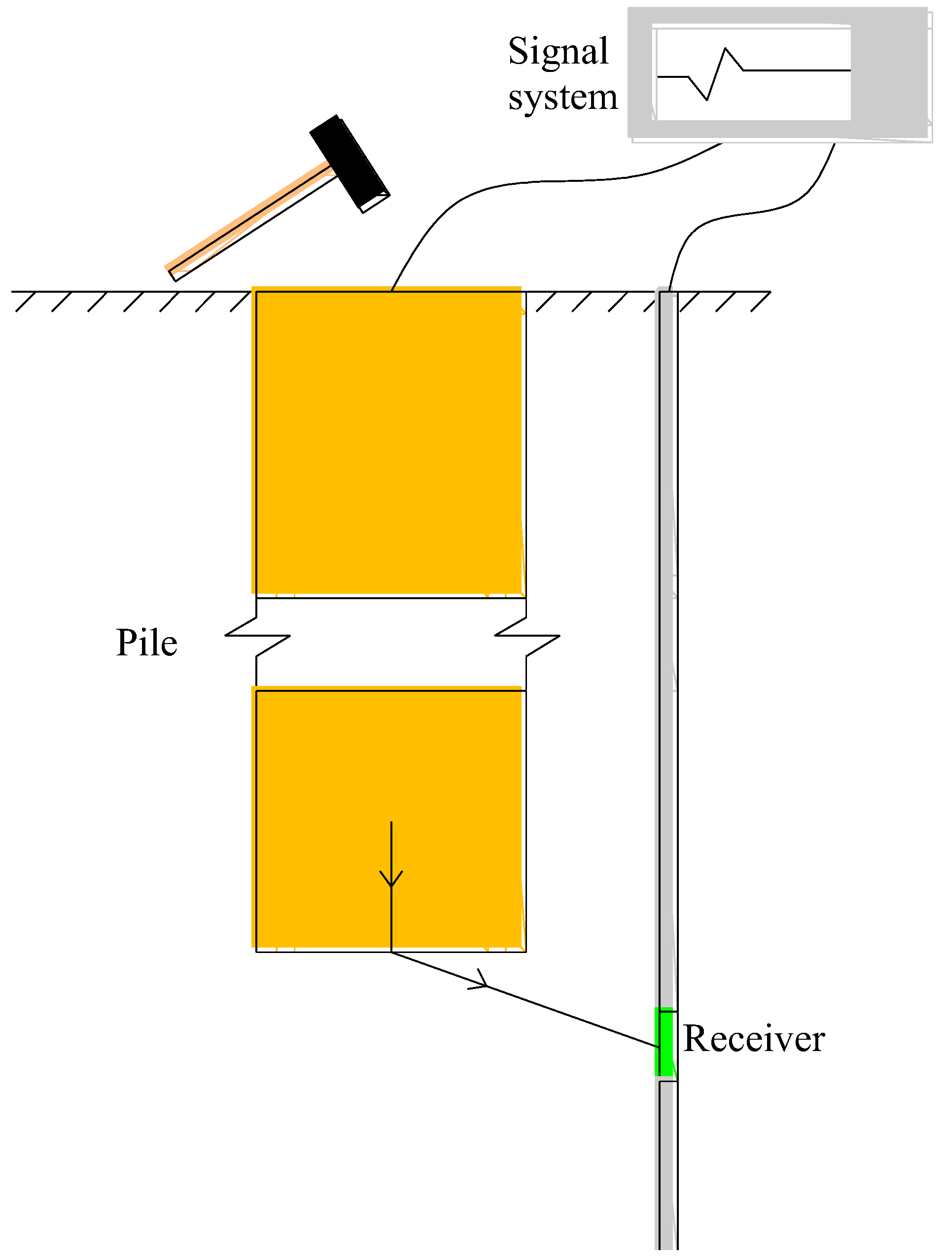
The side-hole transmitted wave method [20] places a detector in the measuring hole near the pile to be tested, then excites vibration at the top or side of the pile foundation, and then uses the detector to collect the transmitted wave of the pile body. Finally, the pile length and pile body quality are analyzed according to the collected wave characteristics, as shown in Figure 2.
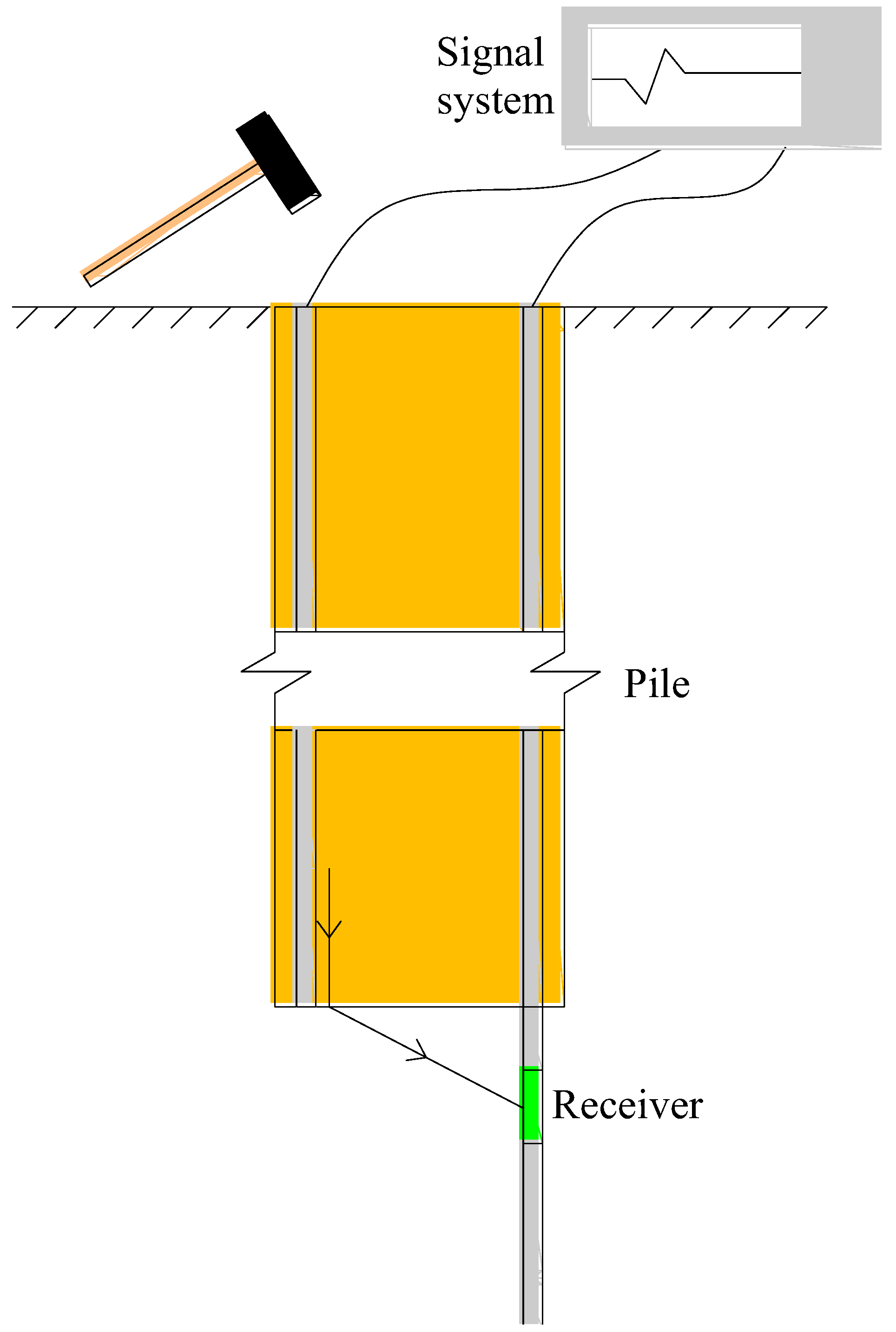
However, due to the limitation of the test site and the large depth of the pile, it is difficult to drill the inclination hole on the side of the pile, so the test method is improved, and a more economical and convenient method of transmitting waves in the pile is proposed. One side is used to provide transmitted waves and the other side is used to receive transmitted waves, as shown in Figure 3. The transmission wave method in the pile can effectively solve the problem of difficulty in taking vertical super long side holes.
During the test, the transmitted wave is generated by hammering with a heavy hammer, and the three-component detector is placed at different depths to receive the transmitted wave. According to the arrival time of the first wave, it can be used to determine the length of the pile and the depth of reinforcement, as shown in Figure 4.
The test of the transmitted wave method in the pile was carried out on the No. 1 pile and No. 2 pile. The main test steps are as follows:
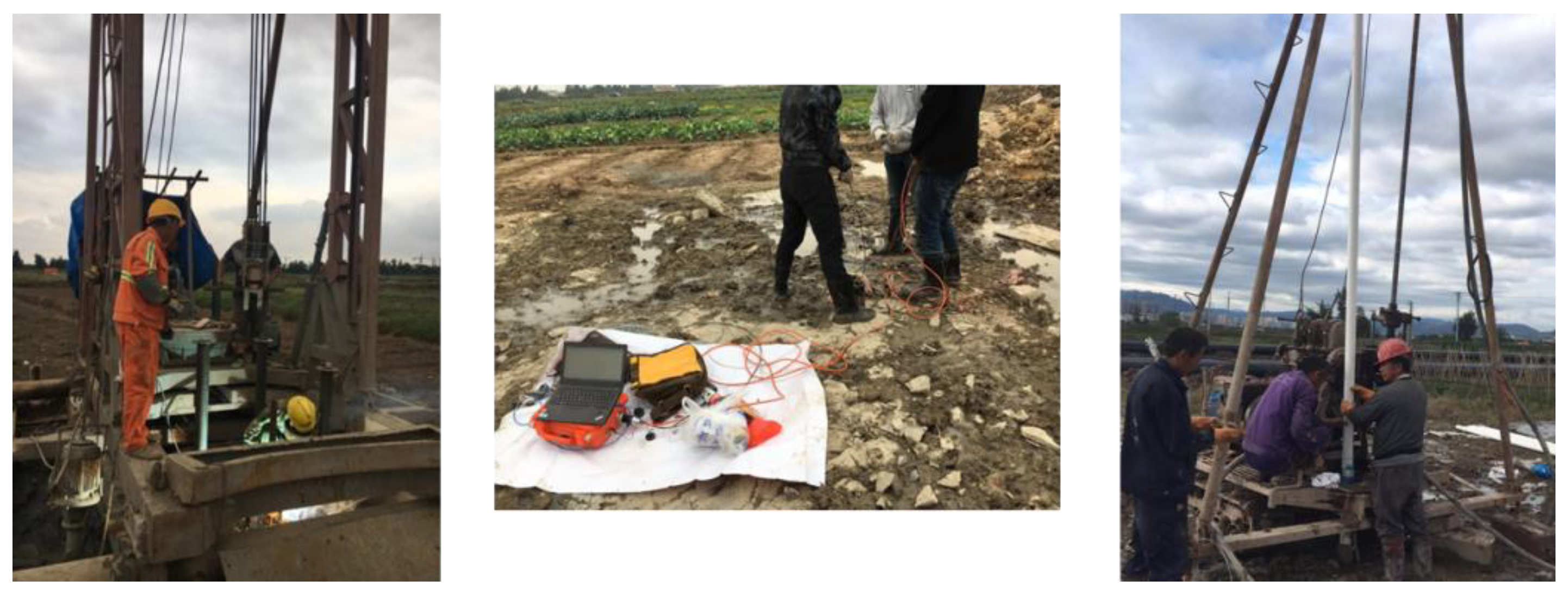
Before the test, the acoustic tubes were processed in the steel bar processing shed on the construction site. Each acoustic tube was 6 m long and 12 cm in diameter. The acoustic tubes were connected by flanges. The acoustic tube is bound onto the steel cage and it goes down into the pile hole together with the steel cage. Finally, the redundant part of the acoustic tube above the ground is cut off. After 28 days of grouting at the bottom of the pile, we drilled holes at the bottom of the acoustic tube and buried the PVC pipe, which is used to place the three-component detector and conduct on-site testing. This part of the test photos is shown in Figure 5.

3.2. Test of Dynamic Penetration

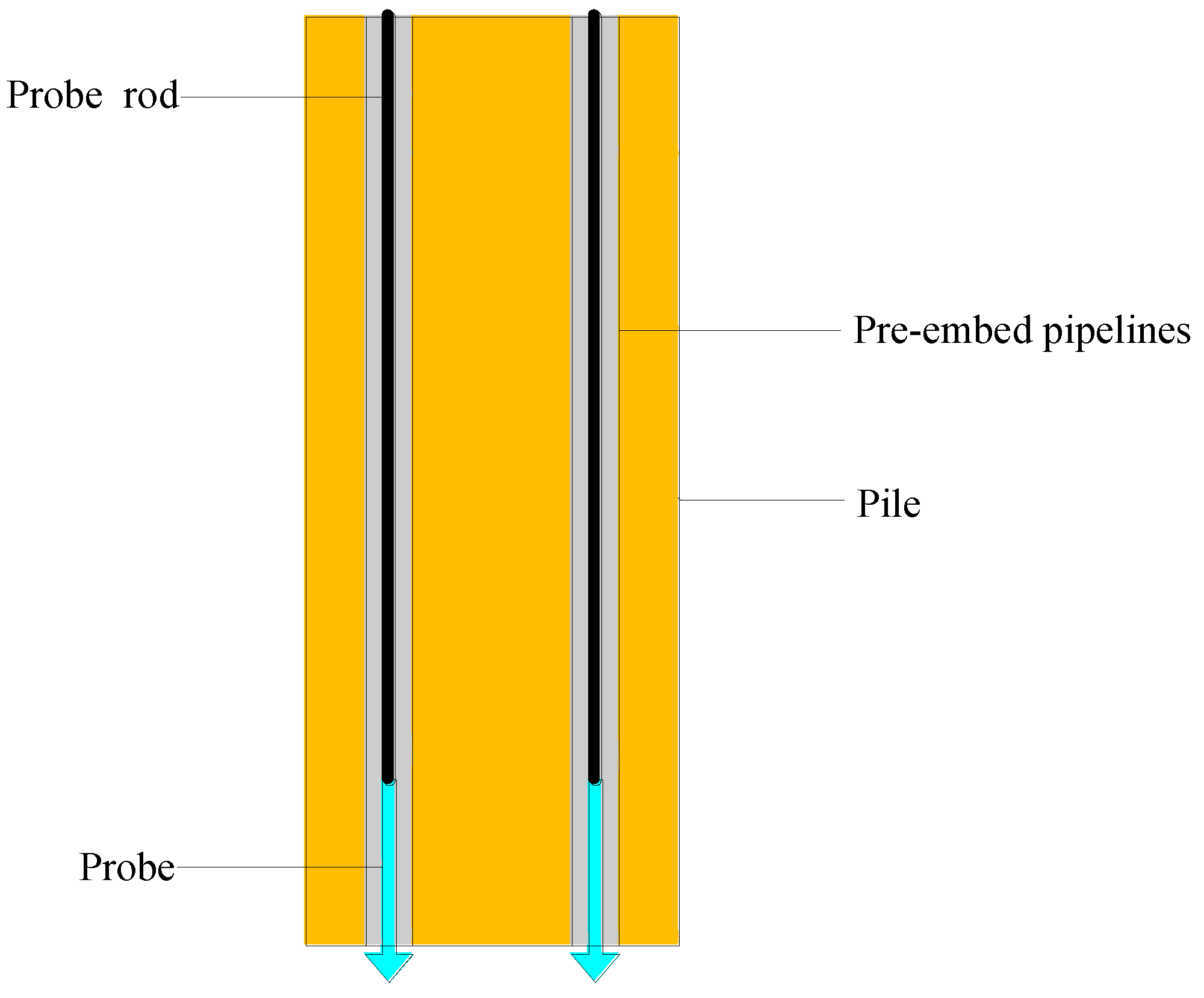
Considering that bored piles are widely used at present, and pile base post-grouting technology is often used in practical projects, it is particularly necessary to detect the effect of pile base grouting. However, the conventional dynamic penetration method cannot test the strength of the soil before and after grouting under the same pile base. In order to solve this problem, this study will bury two pre-embed pipelines at the same time, and the changes in the bearing capacity before and after grouting can be tested on one pile.
Dynamic penetration determines the mechanical properties of the soil according to the number of hammer blows required to penetrate the probe into the soil for a certain distance. Before and after grouting at the pile base, the strength of the soil at the base of the pile is very different. In this study, larger diameter pipelines will be buried in the bored pile in advance, as shown in Figure 6. The pre-embed pipelines can be used for a heavy hammer to penetrate the channel. The grouting reinforcement effect can be determined by the number of hammer blows in the dynamic penetration test before and after grouting.
The strength of the undisturbed soil before grouting and after grouting of the No. 1 pile, No. 2 pile, and No. 3 pile were tested by a heavy-duty dynamic penetration method. The specific parameters of heavy-duty dynamic penetration are shown in Table 2, and the characteristic value of the bearing capacity of the gravel foundation determined by the heavy-duty dynamic penetration number N63.5 is shown in Table 3.
The main test steps are as follows:
Pre-embed two pipelines in the pile when forming a pile; hammer the probe with a heavy hammer from a certain height in a pre-embedded pipeline, record the number of hammer blows and the cumulative penetration (the distance of the wire rope falling); grouting and maintenance at the pile base for 28 d; hammer the probe with the same heavy hammer from the same height in another embedded pipeline, and record the cumulative penetration required for the same number of hammers as in the previous step; and finally, compare the number of hammers and the cumulative penetration curve of the two embedded pipelines to evaluate the grouting effect. This part of the test photos is shown in Figure 7.

4. Results

4.1. Test Analysis of Transmitted Wave in the Pile

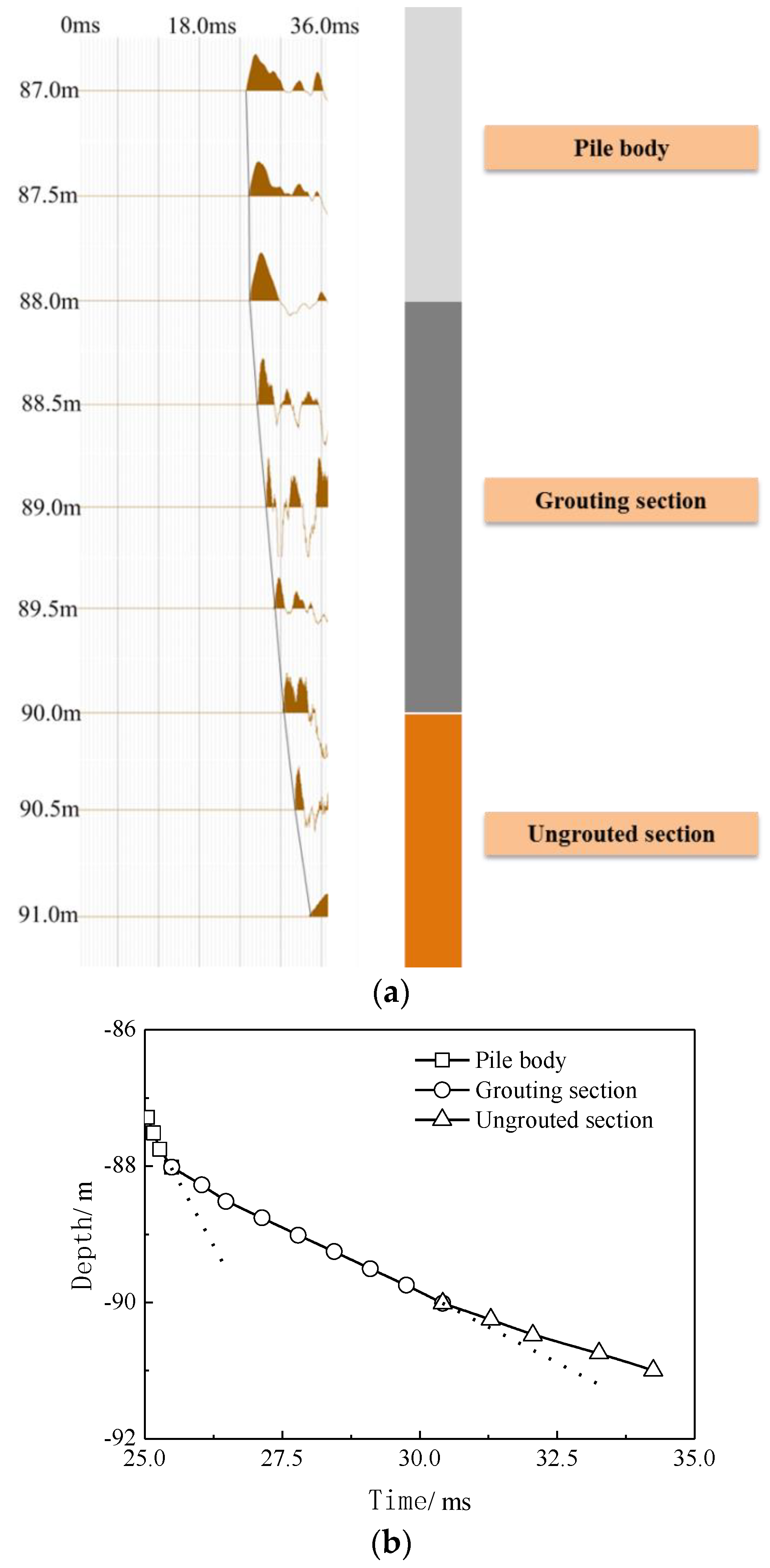
Figure 8a is the original data diagram of the results of the transmission wave test in the No. 1 pile. After data extraction and redrawing, the processing diagram can be obtained, as shown in Figure 8b, which is consistent with Figure 4. Figure 8 shows that the pile bottom elevation of No. 1 pile is −88 m, which is basically consistent with the design elevation, thus verifying the correctness of the method. The second turning point of the curve is −90 m, so the depth of the pile base reinforcement is 2 m. In addition, the wave speed of the pile body is about 3570 m/s, the wave speed of the reinforcement body is about 394 m/s, and the wave speed of the bearing layer is about 285 m/s. From Equations (1) and (2), it can be known that the elastic modulus of the reinforcement is about 1.9 times more than that of the bearing layer.
V p p = E ρ
V s p = ( 1 v ) E ( 1 + v ) ( 1 2 v ) ρ
where E and v are the elastic modulus and Poisson’s ratio, respectively, ρ is the mass density, V p p and V s p are the p-wave velocity of the pile and soil, respectively.
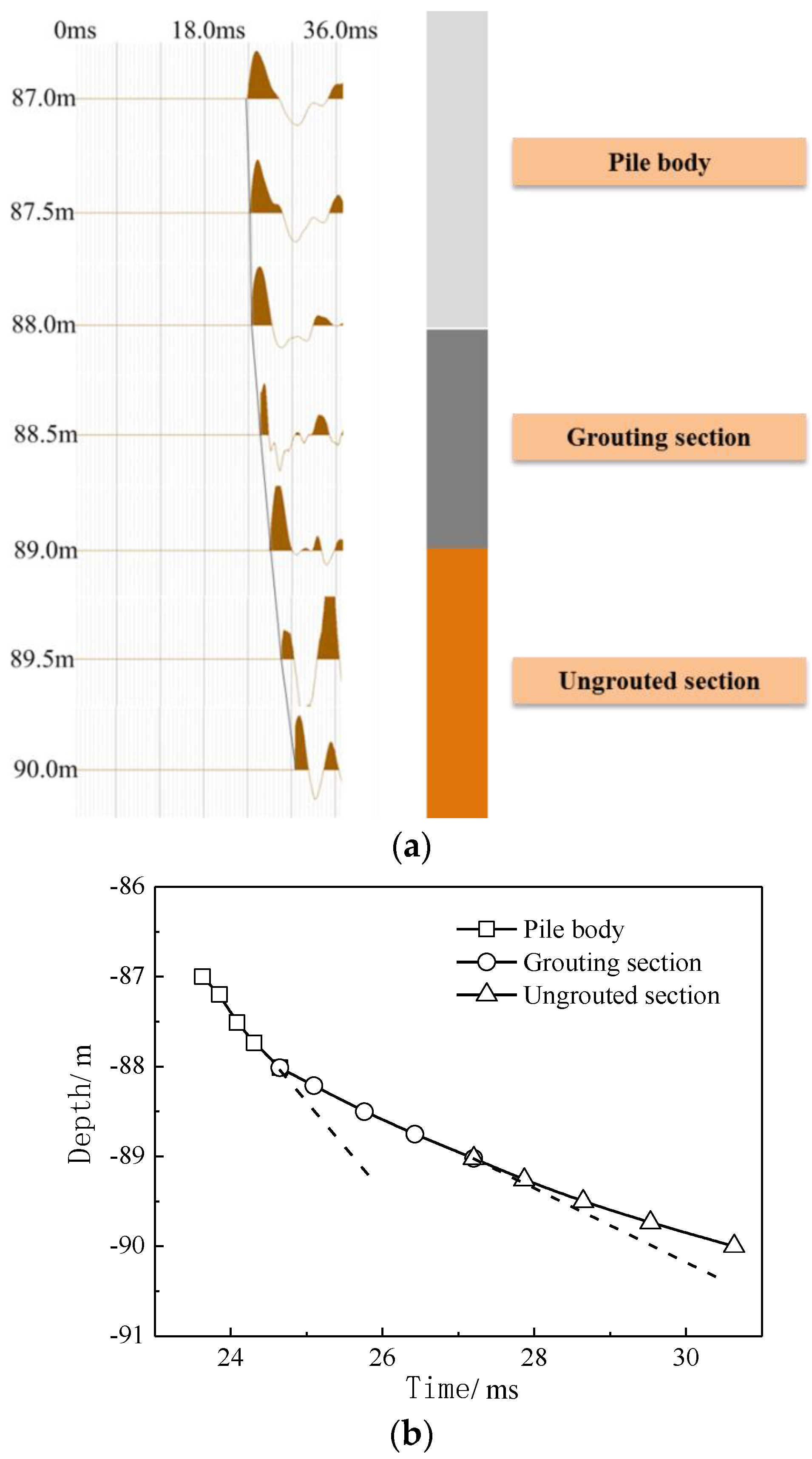
Figure 9a is the original data diagram of the results of the transmission wave test in the No. 2 pile. After data extraction and redrawing, the processing diagram can be obtained, as shown in Figure 9b, which is consistent with Figure 4. Figure 9 shows that the pile bottom elevation of No. 2 pile is −88 m, which is basically consistent with the design elevation, thus verifying the correctness of the method. The second turning point of the curve is −89 m, so the depth of the pile bottom reinforcement is 1 m. In addition, the wave speed of the pile body is about 3453 m/s, the wave speed of the reinforcement body is about 405 m/s, and the wave speed of the bearing layer is about 257 m/s. From Equations (1) and (2), it can be known that the elastic modulus of the reinforcement is about 2.48 times more than that of the bearing layer.
If the shape of the reinforcement body is assumed to be a cylinder passing through the bottom of the pile, the volume formula of the three-dimensional reinforcement body is shown in Equation (3):
V = π R 2 H
If the diameter of the pile bottom is 1.5 m as the diameter of the reinforcement cylinder, it can be seen from the above test that the reinforcement depths of the No. 1 pile and No. 2 pile are 2 m and 1 m, respectively. From Equation (3), V1 = 3.534 m3, V2 = 1.767 m3, the ratio of the two volumes is 2, which is consistent with the ratio of the grouting amount of 500/250, so it can be shown that the assumption about the shape of the cylinder is reasonable.

4.2. Test Analysis of Dynamic Penetration

The test results for the solid dynamic penetration before and after grouting of No. 1~3 piles are shown in Figure 10, Figure 11 and Figure 12.
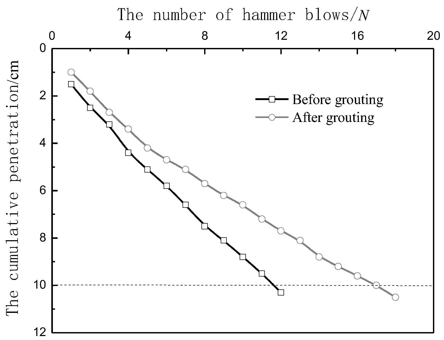
It can be seen from Figure 10 to Figure 12 that the strength of the undisturbed soil at the bottom of the No. 1 pile and the No. 3 pile is relatively large, and relatively speaking, the strength of the undisturbed soil at the bottom of the No. 2 pile is the worst. For example, when the number of hammer blows is 10, the cumulative penetration of the undisturbed soil dynamic penetration of the pile bottom before grouting is 8.8 cm and 9.1 cm for the No. 1 pile and No. 3 pile, respectively, and the cumulative penetration degree for No. 2 pile is 10.5 cm. It is 19.3% and 15.4% larger than the No. 1 pile and No. 3 pile, respectively. This shows that the bearing capacity of the adjacent piles on the same site is still different due to the slight differences in geological and construction conditions [25]; the slope of the curve in the figure is gradually gentle, that is, the single penetration depth of the three piles gradually decreases with the increase in the number of hammer blows. The first hammering depths of the three piles were 1.5 cm, 1.2 cm, and 1.3 cm, and the last hammering depths were 0.8 cm, 0.9 cm, and 0.6 cm, which shows that as the soil at the pile base is continuously hammered and compacted, the strength becomes larger, which conforms to the general law of dynamic penetration [23,24].
The grouting amount of the No. 1 pile is 500 kg. The dynamic penetration results before and after grouting are shown in Figure 10. After the No. 1 pile base is grouted, the number of hammer blows required to reach 10 cm is 17 times. The cumulative depth of dynamic penetration before grouting has reached 10.3 cm, while the cumulative depth after grouting is only 7.7 cm.
The grouting amount of the No. 2 pile is 250 kg. The dynamic penetration results before and after grouting are shown in Figure 11. After the No. 2 pile base is grouted, the number of hammer blows required for dynamic penetration to reach 10 cm is 13 times. The cumulative depth of dynamic penetration before grouting has reached 10.5 cm, while the cumulative depth after grouting is only 8.2 cm.
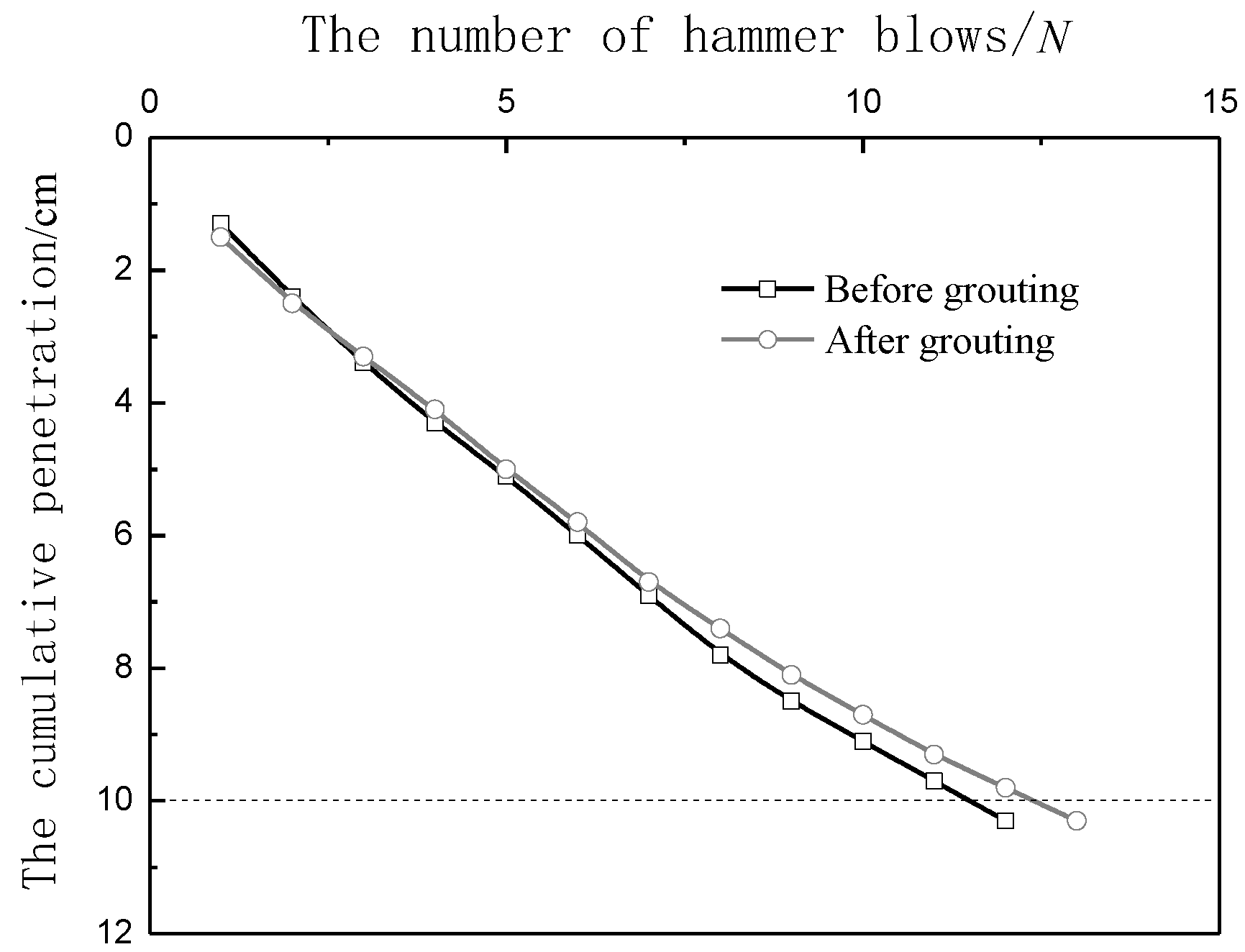
Although the No. 3 pile was not grouted, a dynamic penetration comparison test was also completed at the same time. As can be seen from Figure 12, the number of hammer blows in both tests was about 12, and the curves are roughly coincident, which is consistent with reality.

5. Discussion

Comprehensive analysis, when the cumulative penetration is 10 cm, the number of hammer blows required for the No. 1 pile before grouting is about 12, the No. 2 pile is about 9, and the No. 3 pile is about 12; the number of hammer blows required for the No. 1 pile after grouting is about 17, the No. 2 pile is about 13, and the No. 3 pile is about 12. According to the recommended correction factor for the length of the heavy-duty dynamic penetration rod, the test pile can take a factor of 0.44 [26]. It can be obtained that when the cumulative penetration is 10 cm, the number of hammer blows required for the No. 1 pile before grouting is 5.28, the No. 2 pile is 3.96, and the No. 3 pile is about 5.28; after grouting, the number of hammer blows required for the No. 1 pile is 7.48, the No. 2 pile is 5.72, and the No. 3 pile is about 5.28. According to the data of this test, the characteristic value of the bearing capacity of the foundation soil of the bearing layer is 200 kPa, which corresponds to the characteristic value of the bearing capacity of the gravel foundation when the number of hammer blows is 5 in Table 3, which is the same as the grouting of the three piles in this test [27]. The number of hammer blows before is relatively close, so this table is used to analyze the bearing capacity of the foundation. According to the conversion from the table, the characteristic value of the foundation bearing capacity of the bearing layer of the No. 1 pile before grouting can be obtained as 211.2 kPa, the No. 2 pile is 168.8 kPa, and the No. 3 pile is 211.2 kPa; after grouting, the bearing capacity characteristics of the bearing layer of the No. 1 pile is 299.2 kPa, 228.8 kPa for pile No. 2, and 211.2 kPa for No. 3 pile, which can be seen in Table 4. It can be shown that the foundation bearing capacity of the No. 1 pile before and after grouting increased by 41.7%, and the No. 2 pile increased by 35.5%. The characteristic value of the bearing capacity of the foundation after grouting calculated by this method can also provide reference for similar projects.
From the data of No. 1 and No. 2 piles, the grouting amount increased from 250 kg to 500 kg, and the bearing capacity increased from 35.5% to 41.7%, it shows that when other grouting parameters remain unchanged, increasing the grouting amount can effectively improve the bearing capacity.

6. Conclusions

In this study, a combined testing method of the transmission wave method in the pile and the dynamic penetration test was used to test the effect of base post-grouting on the base soil layer. The proposed combined testing method can effectively estimate the effect of base post-grouting on the base.
(1)
The influencing range of base post-grouting was firstly evaluated by the transmitted wave method in the pile. The depth of the pile base reinforcement was 2 m for No. 1 pile, and 1 m for No. 2 pile, which was consistent with the grouting amount.
(2)
The strength of the soil before and after grouting under the same pile base was measured by the dynamic penetration method. The elastic modulus of the base soil after post-grouting was about twice that of the base soil before grouting.
(3)
The properties of the base soil increased with the grouting amount. The bearing capacity of the base soil layer increased from 35.5% to 41.7%, as the grouting amount increased from 250 kg to 500 kg.

Author Contributions

Conceptualization, H.H. and J.Z.; data curation, H.H.; formal analysis, H.H., Q.J. and F.Y.; funding acquisition, J.Z.; investigation, H.H. and J.M.; methodology, H.H., J.Z. and X.G.; project administration, J.Z. and X.G.; resources, J.Z. and X.G.; software, H.H.; supervision, H.H.; validation, H.H.; visualization, H.H.; writing—original draft, H.H.; writing—review and editing, Q.J., F.Y., J.G. and J.Z. All authors have read and agreed to the published version of the manuscript.

Funding

This research was funded by National Natural Science Foundation of China (52108350 and 52078457).

Institutional Review Board Statement

Not applicable.

Informed Consent Statement

Not applicable.

Conflicts of Interest

The authors declare no conflict of interest.

References

  1. Ng, C.W.; Zhang, L.; Nip, D.C. Response of laterally loaded large-diameter bored pile groups. J. Geotech. Geoenvironmental Eng. 2001, 127, 658–669. [Google Scholar] [CrossRef]
  2. Brown, M.J.; Hyde, A.; Anderson, W. Analysis of a rapid load test on an instrumented bored pile in clay. Geotechnique 2006, 56, 627–638. [Google Scholar] [CrossRef] [Green Version]
  3. Moayedi, H.; Hayati, S. Applicability of a cpt-based neural network solution in predicting load-settlement responses of bored pile. Int. J. Geomech. 2018, 18, 06018009. [Google Scholar] [CrossRef]
  4. Zhang, Q.; Feng, R.; Yu, Y.; Liu, S.; Qian, J. Simplified approach for prediction of nonlinear response of bored pile embedded in sand. Soils Found. 2019, 59, 1562–1578. [Google Scholar] [CrossRef]
  5. Zhou, J.; Yu, J.; Gong, X.; El Naggar, M.H.; Zhang, R. Field study on the behavior of pre-bored grouted planted pile with enlarged grout base. Acta Geotech. 2021, 16, 3327–3338. [Google Scholar] [CrossRef]
  6. Safaqah, O.; Bittner, R.; Zhang, X. Post-Grouting of Drilled Shaft Tips on the Sutong Bridge: A Case History. Geo-Denver 2007, 1–10. [Google Scholar]
  7. Bruce, D. Enhancing the performance of large diameter piles by grouting. Ground Eng. 1986, 19, 9–15. [Google Scholar]
  8. Aurora, R.; Reese, L. Behavior of axially loaded drilled shafts in clay-shales. Design Methods 1976, 172p. Available online: https://trid.trb.org/view.aspx?id=62914 (accessed on 19 September 2022).
  9. Zhang, Z.; Yu, J.; Zhang, G.; Zhou, X. Test study on the characteristics of mudcakes and in situ soils around bored piles. Can. Geotech. J. 2009, 46, 241–255. [Google Scholar] [CrossRef]
  10. Hirayama, H. Load-settlement analysis for bored piles using hyperbolic transfer functions. Soils Found. 1990, 30, 55–64. [Google Scholar] [CrossRef] [Green Version]
  11. Mullins, G.; Winters, D.; Dapp, S. Predicting end bearing capacity of post-grouted drilled shaft in cohesionless soils. J. Geotech. Geoenvironmental Eng. 2006, 132, 478–487. [Google Scholar] [CrossRef] [Green Version]
  12. Mullins, G.; Dapp, S.; Frederick, E.; Wagner, R. Post Grouting Drilled Shaft Tips. Phase I (no. Final Report); Submitted Florida Department of Transportation: Tallahassee, FL, USA, 2001. [Google Scholar]
  13. Dai, G.; Gong, W.; Zhao, X.; Zhou, X. Static testing of pile-base post-grouting piles of the suramadu bridge. Geotech. Test. J. 2011, 34, 34–49. [Google Scholar]
  14. Fang, K.; Zhang, Z.; Zou, J.; Wang, Z. Laboratory studies on pressure filtration in post-grouting of drilled shaft tips in clay. Geotech. Test. J. 2012, 35, 665–671. [Google Scholar] [CrossRef]
  15. Khazaei, J.; Eslami, A. Postgrouted helical piles behavior through physical modeling by fcv. Mar. Georesources Geotechnol. 2017, 35, 528–537. [Google Scholar] [CrossRef]
  16. Wan, Z.; Dai, G.; Gong, W. Field study on post-grouting effects of cast-in-place bored piles in extra-thick fine sand layers. Acta Geotech. 2019, 14, 1357–1377. [Google Scholar] [CrossRef]
  17. Zhou, Z.; Xu, F.; Lei, J.; Bai, Y.; Chen, C.; Xu, T.; Zhang, Z.; Zhu, L.; Liu, T. Experimental study of the influence of different hole-forming methods on the bearing characteristics of post-grouting pile in loess areas. Transp. Geotech. 2021, 27, 100423. [Google Scholar] [CrossRef]
  18. Yao, W.; Qiu, Y.; Chen, Z. Ultimate bearing capacity analysis of a super-long rock-socketed filling pile based on catastrophe theory. Adv. Struct. Eng. 2010, 13, 331–338. [Google Scholar] [CrossRef]
  19. Feng, S.; Lu, S.; Shi, Z. Field investigations of two super-long steel pipe piles in offshore areas. Mar. Georesources Geotechnol. 2016, 34, 559–570. [Google Scholar] [CrossRef]
  20. Davis, A.G. Nondestructive evaluation of existing deep foundations. J. Perform. Constr. Facil. 1995, 9, 57–74. [Google Scholar] [CrossRef]
  21. Pinjarkar, S.G.; Kritzler, R.W.; Rolsing, R.A.; Mccarthy, P.O. Evaluation and load testing of a 100-year-old elevated steel transit structure. Transp. Res. Record 1991, 1290, 252–256. [Google Scholar]
  22. Zhu, J.; Yin, K.; Gong, W.; Xie, F. Discussion about several issues of bi-directional load testing in Chinese, American and European standards. Rock Soil Mech. 2020, 10, 3491–3499. (In Chinese) [Google Scholar]
  23. Coyle, H.M.; Bartoskewitz, R.E. Prediction of shear strength of sand by use of dynamic penetration tests. Transp. Res. Rec. 1980, 749, 46–54. [Google Scholar]
  24. Lin, L.; Li, S.; Sun, L.; Liu, X.; Chen, W. Study of relative compaction for calcareous sand soil using dynamic cone penetration test. Rock Soil Mech. 2020, 08, 2730–2738. (In Chinese) [Google Scholar]
  25. Liu, X.; Jie, X.; You, X.; Xie, F. Study on bearing behavior of large diameter driven steel pipe pile in coral reef geology. Ocean. Eng. 2019, 37, 157–163. [Google Scholar]
  26. Li, H.; Guo, F.; Fu, S.; Hao, W.; Li, Z. Adaptation and correction of dynamic penetration rod length. Earth Sci. 2016, 41, 1249–1258. (In Chinese) [Google Scholar]
  27. Wen, X. The Research of Heavy dynamic Sounding Rod Length Correction Issue. Shenyang Jianzhu Univ. 2015. (In Chinese) [Google Scholar]
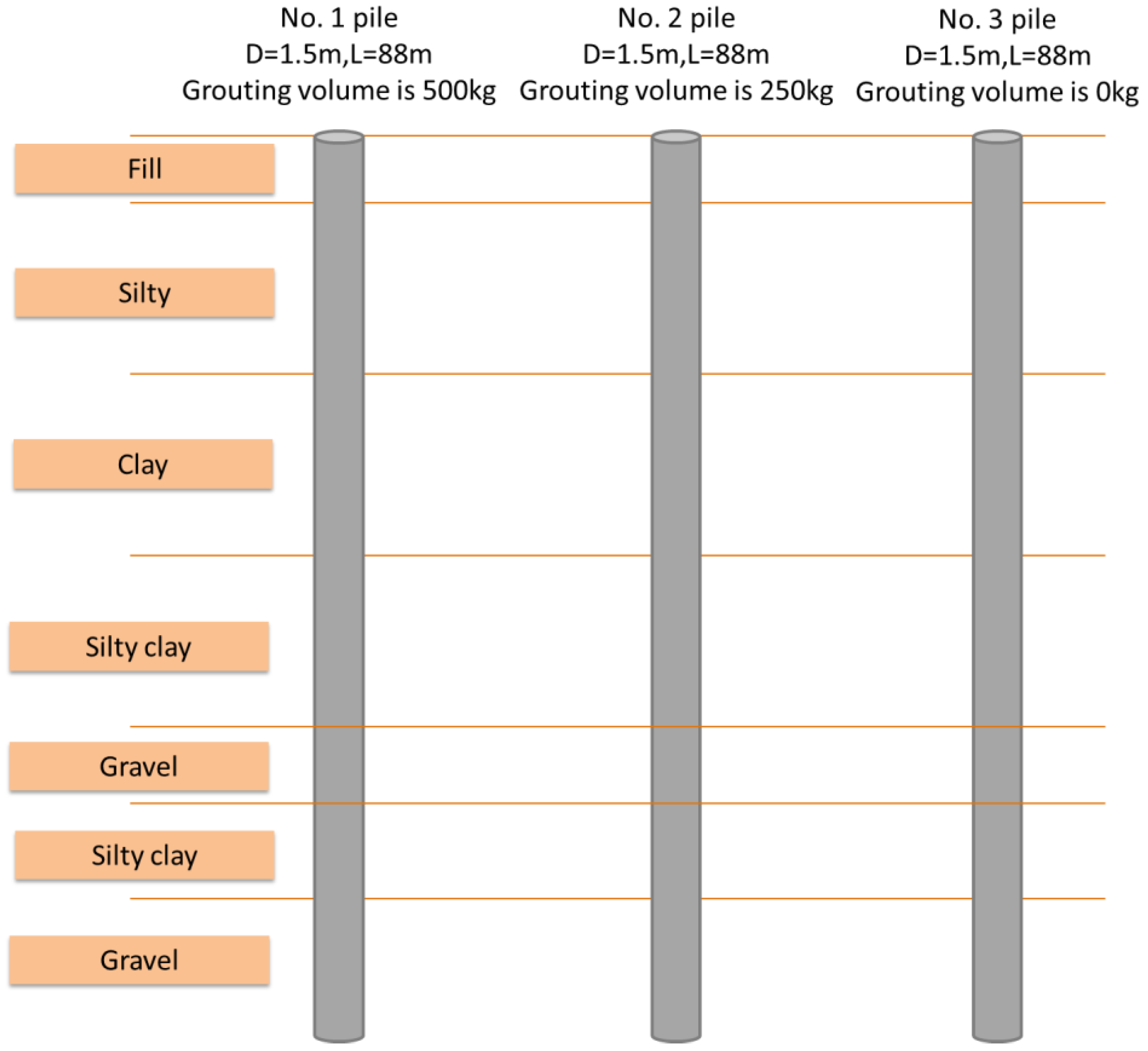
Figure 1. Site schematic diagram.
Applsci 12 10996 g001
Figure 2. Schematic diagram of the side-hole transmitted wave method.
Applsci 12 10996 g002
Figure 3. Schematic diagram of the transmitted wave method in the pile.
Applsci 12 10996 g003
Figure 4. Detection principle of the transmitted wave method in the pile.
Applsci 12 10996 g004
Figure 5. Transmitted wave test in the pile.
Applsci 12 10996 g005
Figure 6. Dynamic penetration device of pile base grouting effect test.
Applsci 12 10996 g006
Figure 7. Dynamic penetration test.
Applsci 12 10996 g007
Figure 8. Test result of transmission wave in the No. 1 pile: (a) original data; (b) processed Data.
Applsci 12 10996 g008
Figure 9. Test result of transmission wave in the No. 2 pile: (a) original data; (b) processed Data.
Applsci 12 10996 g009
Figure 10. Comparison of dynamic penetration test of No. 1 pile before and after grouting.
Applsci 12 10996 g010
Figure 11. Comparison of dynamic penetration test of No. 2 pile before and after grouting.
Applsci 12 10996 g011
Figure 12. Comparison of dynamic penetration test of No. 3 pile before and after grouting.
Applsci 12 10996 g012
Table 1. Physical and mechanical indexes of soil in the test site.
Layer NumberFormation NameH/mγ/(kN·m−3)ES/(MPa)c/(kPa)φ/(°)fa/(kPa)
1Fill2.1
2Silt19.416.52.168.92.855
3Clay23.817.63.0620.35.480
4Silty clay26.118.14.0931.37.6120
5Gravel2.9 200
6Silty clay10.918.94.4541.19.4180
7Gravel18.1 200
Table 2. Heavy-duty dynamic penetration parameters.
Hammer Quality (kg)Drop Distance (cm)Probe Diameter (mm)Probe Cone Angle (°)Probe Rod Diameter (mm)Target Penetration Depth (cm)
107674604210
Table 3. The characteristic value of the bearing capacity of the gravel soil foundation determined by the heavy-duty dynamic penetration number N63.5.
Hammering Times345681012
Characteristic value of foundation bearing capacity (kPa)140170200240320400480
Table 4. Characteristic values of foundation bearing capacity before and after grouting.
Characteristic Value of Foundation Bearing Capacity (kPa)Before GroutingAfter Grouting
No. 1 pile211.2299.2
No. 2 pile168.8228.8
No. 3 pile211.2211.2
Publisher’s Note: MDPI stays neutral with regard to jurisdictional claims in published maps and institutional affiliations.