Abstract
This study investigates the design and sizing of the second life battery energy storage system applied to a residential building with an EV charging station. Lithium-ion batteries have an approximate remaining capacity of 75–80% when disposed from Electric Vehicles (EV). Given the increasing demand of EVs, aligned with global net zero targets, and their associated environmental impacts, the service life of these batteries, could be prolonged with their adoption in less demanding second life applications. In this study, a technical assessment of an electric storage system based on second life batteries from electric vehicles (EVs) is conducted for a residential building in the UK, including an EV charging station. The technical and energy performance of the system is evaluated, considering different scenarios and assuming that the EV charging load demand is added to the off-grid photovoltaic (PV) system equipped with energy storage. Furthermore, the Nissan Leaf second life batteries are used as the energy storage system in this study. The proposed off-grid solar driven energy system is modelled and simulated using MATLAB Simulink. The system is simulated on a mid-winter day with minimum solar irradiance and maximum energy demand, as the worst case scenario. A switch for the PV system has been introduced to control the overcharging of the second life battery pack. The results demonstrate that adding the EV charging load to the off-grid system increased the instability of the system. This, however, could be rectified by connecting additional battery packs (with a capacity of 5.850 kWh for each pack) to the system, assuming that increasing the PV installation area is not possible due to physical limitations on site.
1. Introduction
Global concerns surrounding the decarbonization of energy systems have notably increased over the past years [1]. Distributed energy generation systems such as PV panels are one of the most promising technologies primarily contributing to the building service industry [2]. However, the main improvement to the technology has been in connection with the electrochemical efficiency of the PV cells [3]. Despite notable technological advancements, there are various technical challenges associated with their adoption in the building sector including the mismatch in the supply and demand timing. One of the possible solutions to address this challenge is to install electric storage systems (ESS) [4]. The ESS, integrated with the renewable energy systems equipped with PV panels, especially in the stand-alone (off-grid) systems, is used for peak shaving and power shifting from day time to peak load hours (mostly evenings) [5]. In stand-alone renewable energy systems in buildings, the total energy demand is supplied by solar or other renewable energy sources [6], making the energy supply and demand management an integral part of the system [7,8].
The energy storage systems although contributing positively to the energy management solutions, have considerable environmental impacts [9]. This is mainly associated with the extraction of raw materials such as Cobalt, Nickel, and Lithium, and energy intensive processes when manufacturing Lithium-ion batteries [10]. This impact, however, could be reduced by prolonging the service life of the batteries retired from their first application in EVs, to less demanding applications such as residential buildings [11]. The initial state of health (SoH) of the second life batteries in such applications is generally around 75–80% of their nominal capacity [12]. Such second life applications are also expected to provide financial benefits making renewable energy more affordable and desirable for the end-users [13].
Lithium-ion batteries used in electric vehicles are considered second life when their capacity reaches 80% of their initial value. The lithium-ion batteries can be used in less-stressed applications such as buildings until their end of life. In order to achieve highest life span of the SLBSs, the load stress applied to them should be minimized. For grid-connected systems, it will be managed by the battery management system (BMS) which controls the energy flow through the SLBs, and mostly the extra demand will be applied to the grid. However, in stand-alone systems, the stress level and variations of the load applied to the SLBs are higher than grid-connected systems. In addition, the size of the PVs and SLBs plays a key role in the stand-alone system to find the optimum energy performance of the system as well as achieving the highest life span for the SLBs. On the other hand, as the number of electric vehicles increases, more buildings are equipped with EV charging stations applying a significant extra load to the building energy storage system which may directly affect the SLBs service life. This is the case especially when these systems are designed to cover the building demands excluding EVCS.
Numerous studies have investigated the application of second life batteries for ESS in residential buildings. Hart et al. [14] studied second life batteries in a micro-grid using an equivalent circuit model (ECM) and validated the model against the experimental data. Furthermore, the performance of the microgrid with different architectures was assessed. The results demonstrated that the second life batteries could be successfully installed in grid-connected or islanded microgrid applications uninterrupting the normal operation of the system. Sun et al. [13] have introduced the integration of a 3 MW second life battery ESS with the grid for peak shaving in China. The mathematical modelling of the system as well as a cost-effective model for the BSS is developed. It has been demonstrated that employment of second life batteries in the grid for peak shaving in China is cost beneficial, especially for the grid companies. The impacts of the second life battery packs with a different state of health (SoH) on the performance of the system was investigated by Mathews et al. [15]. The semi-empirical degradation model was used for modelling demonstrating that second life batteries are comparatively more profitable than first life batteries in PV systems. Cusenza et al. [9] developed a mathematical model for the second life battery sizing and optimization of a stand-alone PV system for a net zero energy residential building. The second life battery sizing was performed to achieve the best load match of the building and the results confirmed the optimum ratio of battery size to PVs total power to achieve the best load match in the residential buildings.
Further, Uddin et al. [16], modelled a grid-connected residential building equipped with PV and second life ESS considering building demand in various times during the year. The ECM was used to predict the battery parameters at different times and estimated the battery degradation parameters. The results of their work demonstrated that by considering degradation effects on financial parameters, the second life batteries are no longer cost effective for the customers. The technical assessment of integration of second life batteries with grid-connected PV systems for a residential building is demonstrated in Assuncao et al. [17], by considering a typical European residential building load demand. MATLAB Simulink was used to model the proposed system for three scenarios: without storage, large (Nissan Leaf), and small (Citroen C0) second life battery energy storage system. In the first year, the employment of second life BSS resulted in a reduction of 82.1% and 78.8% in energy exchange between the building and the grid for large and small BSS, respectively. Tong et al. [18] has investigated the integration of second life batteries with an off-grid EV charging station in the United States, where MATLAB SIMULINK has been applied for mathematical modelling of the proposed system. The charging station cost was significantly reduced in some locations, along with the similar performance compared to new batteries in other places. It was evident from the reviewed literature that the integration of the second life battery ESS for a residential building with EV charging station has not been investigated. The main contribution of this study is to reveal the impacts of load increase on the sizing of the second life battery energy storage system. The load applied to the second life battery storage system in this study is the residential building electricity load plus EV charging station.The EV charging stations apply an extra load to the residential building load demand [19].
Accordingly, in this study, the design and sizing of the second life battery ESS applied to a residential building with an EV charging station is investigated. The proposed system is modelled using MATLAB SIMULINK. The performance and stability of the system is assessed in a day in the middle of the winter, with the lowest solar irradiance and highest demand. The assessment considers the second life battery ESS with a different number of packs. It is assumed that the roof area is fully covered with PVs, therefore, the energy supply demand mismatch and the system stability maintenance is accomplished by adjusting the ESS size. The energy assessment and SoH analysis are performed to compare the system energy exchange, degradation, and energy supply demand mismatch in various scenarios.
2. System Description
The study is based on an off-grid PV system designed for the energy consumption of a typical house located in Oxford, UK. The study assesses the impacts of adding EVCS demand on the ESS technical parameters, energy exchange, and degradation. The proposed off-grid renewable energy system with an EVCS component could be listed as PV panels, DC-DC converter, second life battery packs, DC-AC inverter, residential building’ load, and EVCS. The block diagram and components of the proposed energy system is shown in Figure 1. According to the figure, the solar energy is converted to electrical energy by PV panels and some of the generated electrical energy will be stored in the second life battery packs, while the rest of the energy would be consumed directly by the AC consumers such as the residential building electric consumers and EVCS. The load demand profiles are presented in Figure 2 [20,21]. The demand profile represents the average UK household load according to the CREST demand model for 15,000 households in the UK [21]. The red line in Figure 2 indicates the building’s daily electricity load. The EV charging station daily load applied to the system is also shown by the black line in Figure 2. The aggregate hourly load is also calculated based on the building and EV charging station loads as presented in Figure 2.
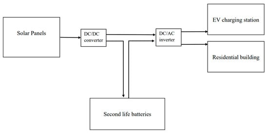
Figure 1.
Schematic block diagram of the proposed off-grid energy system.
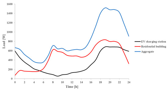
Figure 2.
Different load demands applied to system [20,21].
Figure 3 and Figure 4 demonstrate the block diagrams of the solar system and the second life battery pack. The SoC is monitored frequently during the solution of the model and is used for controlling the switches in the PV system to prevent battery packs from over charging. A MATLAB function is used to calculate the solar irradiance in different times during the day, the details of which will be presented in the next section (see Figure 4).
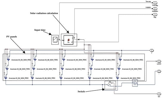
Figure 3.
Block diagram of the solar PV system in MATLAB SIMULINK.
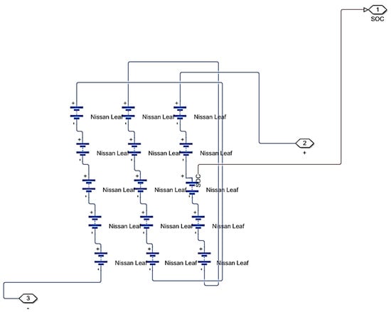
Figure 4.
Block diagram of the 2nd life Nissan Leaf battery pack in MATLAB SIMULINK.
In this study, three scenarios for the off-grid PV system are defined and assessed as presented in Table 1. For the base scenario, two 2nd life battery packs connected in parallel are used, and only residential building demand is applied to the system. The second life batteries and the solar PVs specifications are provided in Table 2 and Table 3. There are 15 s life modules in each battery pack (Figure 4) and the PV panels are connected with a 5 parallel and 3 series configuration (Figure 3).

Table 1.
The defined scenarios in this study.
Table 2.
Second life battery pack specifications [22].
Table 3.
Solar PV panel specifications [23].
3. Mathematical Modelling
As mentioned in the previous section, the mathematical modelling of the proposed system is performed in MATLAB SIMULINK software using the Simscape toolbox. The PV panel and batteries with other components are added to the SIMULINK environment and connected to each other with the desired architecture.
3.1. Solar PV Panels
For calculation of the solar irradiance based on the geographic location (Oxford, UK) and other technical parameters such as the tilt angle of the panel, a model has been designed in MATLAB function in SIMULINK, which calculates the solar irradiance in various simulation steps. For the calculation of beam radiation incidence angle on a surface (), Equation (1) is employed [24]:
where , , , and are declination, latitude, slope, hour angle and surface azimuth angle, respectively [24]. and are assumed to be 0° and 30°, respectively, since most of the houses in the UK has 30° slope on their ceilings, where PV panels arebe installed. The equation of Cooper is used for calculation of declination [24]:
where n is the number of days during the year. Further, the radiation on the tilted plane () could be calculated by Equation (3) [24,25]:
where is extraterrestrial radiation and assumed as 1367 W/m2 in this study [1]. To calculate the beam and diffuse radiations transmitted through a clear atmosphere, the following equations are applied based on Hottel’s method [1,24]:
and are the atmospheric transmittance for beam and diffuse radiations, consecutively. Further information about the parameters used in Equations (4) and (5) (such as , and ) can be found in this reference [24]. Finally, the clear-sky radiation () is obtained using Equation (6) [24]:
The output current of the PV panel is given by [26]:
where, and are diode saturation currents for diodes 1 and 2 shown in Figure 5, respectively. is the thermal voltage, and are diode emission coefficients and is solar-generated current, respectively. The mentioned PV parameters are obtained from MATLAB SIMULINK Simscape library for Amerisolar PV panel the specifications of which are provided in Table 3 [26].
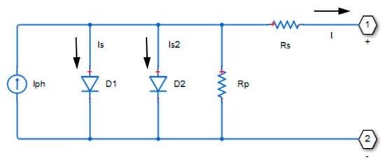
Figure 5.
Block diagram of the equivalent circuit used for modeling PV cell in MATLAB.
3.2. Second Life Battery Pack
Rint ECM [27] was used for modelling the second life batteries in this study. Besides, the ECM model contains an ideal voltage source representative of OCV as the function of SoC with resistors to calculate the internal ohmic losses [28]. The output of this systems is calculated by the following Equation (8):
The experimental data for the parameters in this model is obtained from the literature [22,29,30,31]. In Nissan Leaf prismatic module, there are two cells integrated in a series configuration. In the reference [22], the Nissan Leaf battery is aged using an accelerated ageing profile (Figure 6) [22] in which the second life modules are put under constant current-voltage charging (=1C) and constant current discharging (=1C) at 25 °C environmental temperature. The reference performance test (RTP) is done every 25 cycles to measure the module capacity fade and HPPC test [22]. The HPPC test results are used to fit ECM Rint model parameters the results of which are shown in Figure 7, Figure 8 and Figure 9.
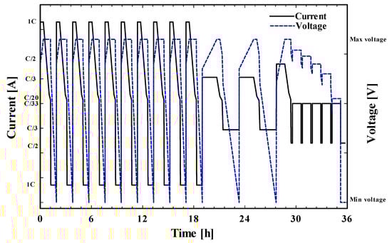
Figure 6.
The accelerated ageing profile and RTP test for degradation analysis of the Nissan Leaf second life battery.
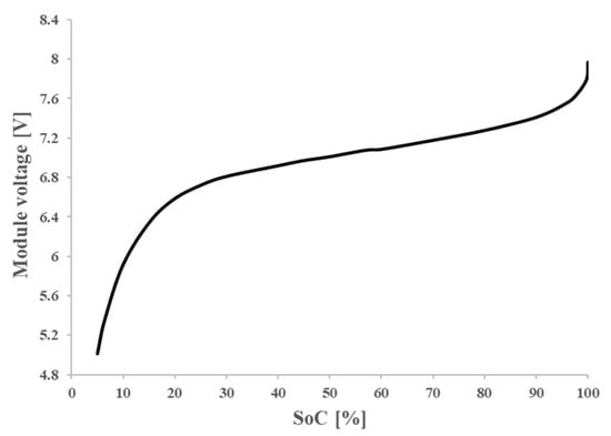
Figure 7.
Nissan leaf second life battery voltage variations in various SoCs [22,29,30,31].
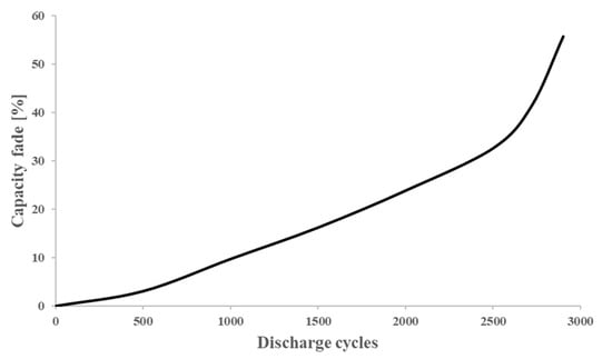
Figure 8.
Nissan leaf second life battery capacity fade in various discharge cycles [22,29,30,31].
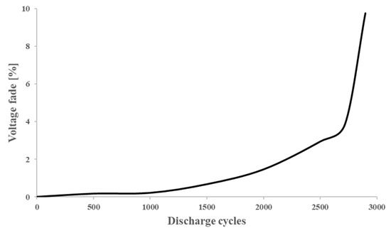
Figure 9.
Nissan leaf second life battery voltage fade in various discharge cycles [22,29,30,31].
4. Results and Discussions
As the main aim of this study is to assess the impacts of second life battery sizing and demand variations on the energy performance of the system, a two-way coupling between the developed second life batteries and solar cells is performed. The operating voltage of the solar cells will be affected by the variation of second life batteries voltage leading to their efficiency variations which are considered in this paper. Accordingly, the solar system modelling is also performed and the impacts of extra load addition and SLB size increase on solar power generation are presented in Section 4.1. The energy exchange between the components and battery operational parameters is demonstrated during the day in Section 4.2 and Section 4.3.
4.1. Impacts on Solar Power Generation
The developed mathematical model has been solved for 24 h in a day (17 January) in the middle of winter in Oxford, UK. In particular, the main reason for choosing a day at the middle of winter is to assess the performance of the system and ESS when the energy input (solar irradiance) is at its minimum values [4]. The solar irradiance is calculated using the model presented in Section 3.1. In addition, the simulation has considered 3600s as the time step. Figure 10 shows the aggregation of solar beam and diffuse radiations transmitted through the atmosphere installed on the tilted plane (PV panels).
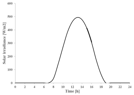
Figure 10.
Solar irradiance (clear-sky radiation) at various times during the day on 17 January.
Figure 11 demonstrates the current output of the PVs to the system during the day for different scenarios. As mentioned before, a switch, controlled by the batteries’ SoC parameter is adopted to prevent the batteries from overcharging. Therefore, the switch will break the connection between the PVs and the battery storage system when the batteries are overcharged. The activation time of the switch can be figured out in Figure 11. For the base scenario (black line), in which only residential building demand is applied to the system, the switch is turned to active mode right after reaching the peak current value at 1 PM. The extra power generated by PVs would not be directed to the system afterward resulting in a sharp increase in PV current flow through the system after 1 PM. An increase of second life battery pack size by an increment of the number of modules from 2 to 4, when extra EVCS load is applied, leads to an increased PV system current flow to the system after reaching peak hours. This is due to an increase in the overcharging limit of the energy storage system and higher amounts of stored energy. Accordingly, the switch activation time is delayed by an increase in the number of packs.
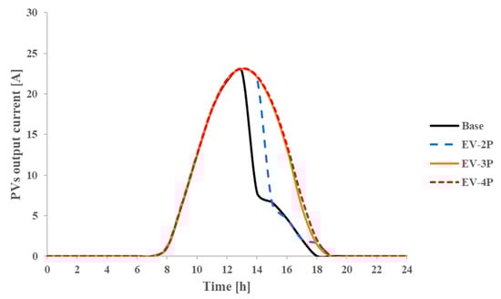
Figure 11.
Second life battery SoC for different scenarios at various times during the day.
4.2. Impacts on Second Life Battery
Figure 12 and Figure 13 show the current and the voltage of the second life battery packs during a day under different scenarios. The addition of the EVCS load demand leads to a decrease of the SLBs charging current peak up to approximately 10% as shown in Figure 12 due to the increment of the system demand. Furthermore, the peak discharge current is also increased and when the EVCS load is applied to the system. Figure 12 also reveals that the pack size increment will extend the charging capacity of the ESS as the integral of the charging current curve for the orange and red lines (3 and 4 packs) are higher than the curve representing the EV-2P scenario. This is due to the activation of the switch reaching the maximum charge capacity of the batteries. The peak voltage of the second life battery packs decreased with the increase in the number of packs as shown in Figure 13, primarily due to the increase in the total capacity of the system and gaining a more stable operational voltage. In Figure 13, reaching the maximum voltage of the ESS is delayed by an increase in the number of SLB packs. The maximum voltage of the ESS on a full charge. By increment of SLB size to 17.55 kWh and 23.4 kWh, in EV-3P and EV-4P scenarios, the peak voltages dropped to 116 V and 111 V, respectively. This is due to an increase in capacity resulting in a decrement in voltage variations of ESS and an extension of the SLB life span.

Figure 12.
Second life battery current for different scenarios during the day.
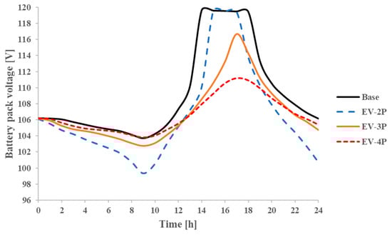
Figure 13.
Second life battery voltage for different scenarios in various times during the day.
Figure 14 presents the SoC variations of the second life battery packs in transient conditions during the day for different scenarios. In particular, the comparison of the base and EV-2P scenarios (both with two battery packs) indicates that adding extra load demand to the system (EV charging station load) results in a rapid discharge of the battery packs from 00.00 to 01.00. Furthermore, the second life battery packs in the EV-2P scenario would be fully charged by approximately 1 h delay compared to the base scenario (which is fully charged at around 14.00). The final SoC of the battery packs also decreased dramatically from 60% (base scenario) to 26% (EV-2P scenario) by adding EVCS load to the system which could result in a significant mismatch between load and energy generation for the next day. To solve this issue the number of battery packs are increased in scenarios EV-3P and EV-4P to 3 and 4 packs, by assuming that the number of PVs are constant. According to Figure 10, by increasing the number of battery packs, the discharging curve between 10.00 to 12.00 is shifted upward by nearly 10%, and the SoC peak has decreased steeply due to the increased capacity of the ESS. Furthermore, the final SoC has increased by escalating the number of battery packs to nearly 53% for the EV-4P scenario. This suggests that increasing the SLB EES size up to 23.4 kWh would be beneficial in gaining a stable energy exchange between the components and reducing the energy generation-consumption mismatch in the proposed system. The main drawback of the size increment of energy storage system would be the increase in its cost, which might be solved by the employment of SLBs given their relatively lower price when compared with brand new batteries.
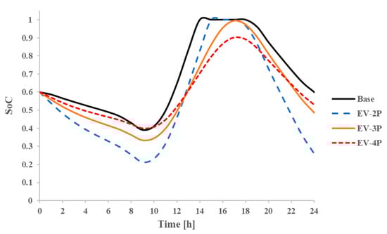
Figure 14.
Second life battery SoC for different scenarios in various times during the day.
4.3. Energy Exchange Analysis
In this section, the energy exchange between the main components of the system; ESS, PVs, and the demand side is demonstrated. Table 4 presents the energy generated by the solar system against the demand side’s consumption. For the base scenario, in which the solar system is designed to cover only the residential building demand, a significant difference is not observed between energy supply and demand. However, the aggregated demand has overcome the supply energy value by adding an extra load to the solar system. The difference between the energy supply and demand needs to be compensated by the amount of energy available in the batteries (the initial SoC of the batteries equals 60% in the simulations) in this scenario (EV-2P). This must be noted that the simulations are performed by considering the worst-case scenario; the solar irradiance and residential building energy demand are at their minimum and maximum rates during the year, respectively. The mismatch between energy supply and demand is expected to be minimum in the warmer months of the year. Table 4 indicates that increasing the number of second life batteries results in minimizing the difference between the energy supply and demand, which could increase the stability of the proposed energy system. The hourly energy exchange rate between the system components is shown in Figure 15a–d for different scenarios.
Table 4.
Energy generation and demand for different scenarios for the proposed day.
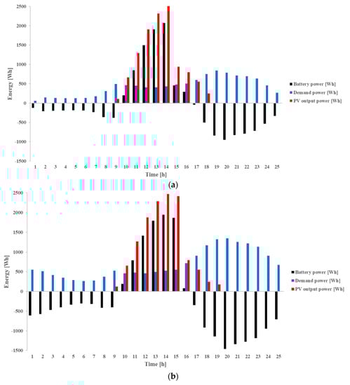
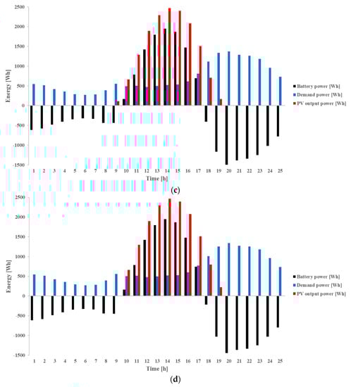
Figure 15.
Proposed system hourly energy exchange for different components in (a) Base, (b) EV-2P, (c) EV-3P and (d) EV-4P scenarios.
Table 4 presents the energy generation and demand for different scenarios in this study. By adding extra EVCS load to the system in the EV-2P scenario, while the number of SLB packs is kept constant (compared to the base scenario), the minimal increase in PV panel power generation is seen due to variations of their operating voltage affected by battery packs voltage variations shown in Figure 13. An increase in SLB packs’ size to 17.55 kWh (EV-3P) and 23.4 kWh (EV-4P) leads to an increase in PV panel energy generation by 21% and 21.27%, respectively, resulting from an increase in electricity storage capacity which allows higher rates of energy storage and lowering variations of PV panels operating voltage.
4.4. Impacts of ESS’ SoH on Stability of the System
The SoH of the second life batteries would be decreased over time and reduce the total capacity of the ESS system. This could directly affect the off-grid system stability in terms of energy exchange between ESS and the other components. Additionally, the difference between the initial charge of the SLBs and their state of charge at the end of the day can be used as the indicator of energy storage system stability. If the SoC at the end of the day would be much lower than SoC at the beginning of the day, it suggests that the discharging rate of the SLBs is higher than their charging rate. Therefore, the ESS charging and discharging stability depends on two parameters: storage size and generation rate. The storage size is increased by the increment of the number of SLB packs; however, it will be also affected by cycle ageing of the batteries leading to decrement in size withbthe passing of time (also charging and discharging cycles). In this section, the impacts of SLBs sizing and cycle ageing on ESS stability are investigated. The difference between the initial and the final SoC is defined as the primary indicator of system stability in this study, which could be expressed as:
where , , and are second life battery SoC difference, initial SoC and final SoC, respectively.
The effects of second life batteries’ ageing on the system stability is illustrated in Figure 16 and Figure 17 for the scenarios with extra EVCS loads. When EVCS load is applied, the stability of the system could be maintained by increasing the number of battery packs, due to the reduction of SoC difference. This translates to 4 battery packs in this study to hold the system stability at an acceptable level before reaching 2000 discharge cycles and approximately 60% SoH, since the SoC difference remains almost constant until reaching these points, as shown in Figure 16 and Figure 17.
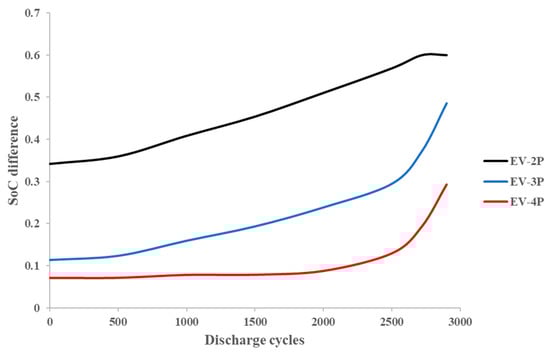
Figure 16.
The SoC difference in different second life batteries discharge cycles for various scenarios.
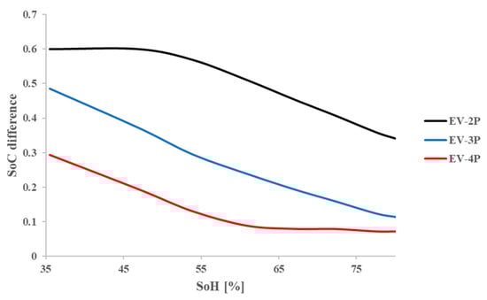
Figure 17.
The SoC difference in different second life batteries SoHs for various scenarios.
The impacts of battery sizing on the energy flow in a stand-alone PV system equipped with second life ESS is investigated while the system is designed based on the worst-case scenario. The results of this study revealed the relation between SLB SoC and SoH which can be used for programming battery management systems. Since most of the PVs in residential buildings are connected to the grid, the effects of employment of different SLB ESS sizes on the energy performance of such a system is not considered which can be counted as the disadvantage of this study.
The experimental data for Nissan Leaf, collected from the literature, are obtained by degradation analysis of the SLBs using accelerated ageing profile (charging and discharging c-rates of 1C) and consequently the ESS model is not validated against the battery empirical tests at various C-rates. Its impacts, therefore, on the degradation of the batteries is neglected in this study.
5. Conclusions
In this paper, the battery sizing and technical assessment of an energy system with a second life energy storage system and an off-grid PV energy system is performed. The main aim of this paper is to investigate the effects of adding extra EV charging station load on the ESS performance applied to a residential building. In addition, a parametric study is performed to assess the SLBs’ size variations in the ESS when an extra load is applied. The proposed case study residential building is located in Oxford. This paper has developed a novel methodology for assessing the off-grid PV system stability and minimizing the energy supply–demand mismatch. The proposed off-grid system with second life ESS has been mathematically modelled in MATLAB SIMULINK. The system is simulated considering the worst-case scenario on a day in the middle of winter, when the solar irradiation and demand are at their minimum and maximum levels, respectively. The configuration of the second life ESS is accomplished by utilizing Nissan Leaf retired battery modules with an 80% SoH. The main conclusions drawn from the analysis can be listed as:
- An increase in SLBs size, when an extra EV charging load is applied, leads to a voltage peak drop in the second life battery. The increase in the number of SLB packs to 4 resulted in a 7.5% voltage peak drop of ESS.
- Adding EV charging station demand to the off-grid PV driven system, which has been designed to cover residential building demand (with two second life battery packs), expectedly resulted in instabilities in energy exchange between different components of the system during the year. Assuming that there is no extra space left on the building roof to add PV panels, increasing the number of second life battery packs was explored with the findings suggesting that an installed capacity equivalent to 4 battery packs for the studied residential building would minimize the energy mismatch between the energy supply and demand. This occurs before reaching 2000 discharge cycles and approximately 60% SoH (the final SoC of the ESS increased to nearly 53% for the case with 4 battery packs).
- When EVCS load has been applied to the residential load demand, the stability of the system could be improved by increasing the number of second life batteries due to the minimal differences in the initial and final SoC of the second life ESS. This is also beneficial in terms of cost, given that second life batteries have a lower price than brand new batteries.
Author Contributions
Conceptualization, S.R., D.M., P.H. and A.A.; Formal analysis, F.S.; Funding acquisition, A.A.; Methodology, S.R., D.M., P.H. and A.A.; Software, F.S.; Supervision, S.R., D.M., P.H. and A.A.; Validation, F.S.; Writing—original draft, F.S., S.R., D.M. and P.H.; Writing—review and editing, F.S. All authors have read and agreed to the published version of the manuscript.
Funding
This research received no external funding.
Institutional Review Board Statement
Not applicable.
Informed Consent Statement
Not applicable.
Data Availability Statement
The related data are presented within the manuscript.
Conflicts of Interest
The authors declare no conflict of interest.
Nomenclature
| EV | Electric vehicle |
| PV | Photovoltaic panel |
| ESS | Energy storage system |
| SoC | State of charge |
| SLB | Second life battery |
| SoH | State of health |
| EVCS | Electric vehicle charging station |
| CS | Charging station |
| ECM | equivalent circuit model |
References
- Salek, F.; Eshghi, H.; Zamen, M.; Ahmadi, M.H. Energy and exergy analysis of an atmospheric water generator integrated with the compound parabolic collector with storage tank in various climates. Energy Rep. 2022, 8, 2401–2412. [Google Scholar] [CrossRef]
- Cui, C.; Zou, Y.; Wei, L.; Wang, Y. Evaluating combination models of solar irradiance on inclined surfaces and forecasting photovoltaic power generation. IET Smart Grid 2019, 2, 123–130. [Google Scholar] [CrossRef]
- Obeidat, F. A comprehensive review of future photovoltaic systems. Sol. Energy 2018, 163, 545–551. [Google Scholar] [CrossRef]
- Mohamed, A.A.R.; Morrow, D.J.; Best, R.J.; Cupples, A.; Bailie, I.; Pollock, J. Distributed battery energy storage systems operation framework for grid power levelling in the distribution networks. IET Smart Grid 2021, 4, 582–598. [Google Scholar] [CrossRef]
- Campana, P.E.; Cioccolanti, L.; François, B.; Jurasz, J.; Zhang, Y.; Varini, M.; Stridh, B.; Yan, J. Li-ion batteries for peak shaving, price arbitrage, and photovoltaic self-consumption in commercial buildings: A Monte Carlo Analysis. Energy Convers. Manag. 2021, 234, 113889. [Google Scholar] [CrossRef]
- Uzair, M.; Rehman, N.U.; Yousuf, M.U. Sensitivity analysis of capital and energy production cost for off-grid building integrated photovoltaic systems. Renew. Energy 2022, 186, 195–206. [Google Scholar] [CrossRef]
- Zand, M.; Nasab, M.A.; Sanjeevikumar, P.; Maroti, P.K.; Holm-Nielsen, J.B. Energy management strategy for solid-state transformer-based solar charging station for electric vehicles in smart grids. IET Renew. Power Gener. 2020, 14, 3843–3852. [Google Scholar] [CrossRef]
- Li, C.; Zheng, Y.; Li, Z.; Zhang, L.; Zhang, L.; Shan, Y.; Tang, Q. Techno-economic and environmental evaluation of grid-connected and off-grid hybrid intermittent power generation systems: A case study of a mild humid subtropical climate zone in China. Energy 2021, 230, 120728. [Google Scholar] [CrossRef]
- Cusenza, M.A.; Guarino, F.; Longo, S.; Mistretta, M.; Cellura, M. Reuse of electric vehicle batteries in buildings: An integrated load match analysis and life cycle assessment approach. Energy Build. 2019, 186, 339–354. [Google Scholar] [CrossRef]
- Costa, C.; Barbosa, J.; Gonçalves, R.; Castro, H.; Del Campo, F.; Lanceros-Méndez, S. Recycling and environmental issues of lithium-ion batteries: Advances, challenges and opportunities. Energy Storage Mater. 2021, 37, 433–465. [Google Scholar] [CrossRef]
- Cusenza, M.A.; Guarino, F.; Longo, S.; Ferraro, M.; Cellura, M. Energy and environmental benefits of circular economy strategies: The case study of reusing used batteries from electric vehicles. J. Energy Storage 2019, 25, 100845. [Google Scholar] [CrossRef]
- Wang, T.; Jiang, Y.; Kang, L.; Liu, Y. Determination of retirement points by using a multi-objective optimization to compromise the first and second life of electric vehicle batteries. J. Clean. Prod. 2020, 275, 123128. [Google Scholar] [CrossRef]
- Sun, B.; Su, X.; Wang, D.; Zhang, L.; Liu, Y.; Yang, Y.; Liang, H.; Gong, M.; Zhang, W.; Jiang, J. Economic analysis of lithium-ion batteries recycled from electric vehicles for secondary use in power load peak shaving in China. J. Clean. Prod. 2020, 276, 123327. [Google Scholar] [CrossRef]
- Hart, P.; Kollmeyer, P.; Juang, L.; Lasseter, R.; Jahns, T. (Eds.) Modeling of second-life batteries for use in a CERTS microgrid. In Proceedings of the 2014 Power and Energy Conference at Illinois (PECI), Champaign, IL, USA, 28 February–1 March 2014. [Google Scholar]
- Mathews, I.; Xu, B.; He, W.; Barreto, V.; Buonassisi, T.; Peters, I.M. Technoeconomic model of second-life batteries for utility-scale solar considering calendar and cycle aging. Appl. Energy 2020, 269, 115127. [Google Scholar] [CrossRef]
- Uddin, K.; Gough, R.; Radcliffe, J.; Marco, J.; Jennings, P. Techno-economic analysis of the viability of residential photovoltaic systems using lithium-ion batteries for energy storage in the United Kingdom. Appl. Energy 2017, 206, 12–21. [Google Scholar] [CrossRef]
- Assunção, A.; Moura, P.S.; de Almeida, A.T. Technical and economic assessment of the secondary use of repurposed electric vehicle batteries in the residential sector to support solar energy. Appl. Energy 2016, 181, 120–131. [Google Scholar] [CrossRef]
- Tong, S.J.; Same, A.; Kootstra, M.A.; Park, J.W. Off-grid photovoltaic vehicle charge using second life lithium batteries: An experimental and numerical investigation. Appl. Energy 2013, 104, 740–750. [Google Scholar] [CrossRef]
- Torres-Sanz, V.; Sanguesa, J.A.; Martinez, F.J.; Garrido, P.; Marquez-Barja, J.M. Enhancing the Charging Process of Electric Vehicles at Residential Homes. IEEE Access 2018, 6, 22875–22888. [Google Scholar] [CrossRef]
- Sprake, D.; Vagapov, Y.; Lupin, S.; Anuchin, A. (Eds.) Housing estate energy storage feasibility for a 2050 scenario. In Proceedings of the 2017 Internet Technologies and Applications (ITA), Guangzhou, China, 26–28 May 2017. [Google Scholar]
- Pimm, A.J.; Cockerill, T.T.; Taylor, P.G. The potential for peak shaving on low voltage distribution networks using electricity storage. J. Energy Storage 2018, 16, 231–242. [Google Scholar] [CrossRef]
- Braco, E.; Martín, I.S.; Berrueta, A.; Sanchis, P.; Ursúa, A. Experimental assessment of cycling ageing of lithium-ion second-life batteries from electric vehicles. J. Energy Storage 2020, 32, 101695. [Google Scholar] [CrossRef]
- Available online: https://www.enfsolar.com/pv/panel-datasheet/crystalline/44143 (accessed on 1 September 2022).
- Duffie, J.A.; Beckman, W.A. Solar Engineering of Thermal Processes; Wiley: Hoboken, NJ, USA, 2013. [Google Scholar]
- Salek, F.; Rahnama, M.; Eshghi, H.; Babaie, M.; Naserian, M.M. Investigation of Solar-Driven Hydroxy gas production system performance integrated with photovoltaic panels with single-axis tracking system. Renew. Energy Res. Appl. 2022, 3, 31–40. [Google Scholar]
- Solar Cell. Available online: https://uk.mathworks.com/help/physmod/sps/ref/solarcell.html;jsessionid=bdf3b2865e01ab9c5896c9e033dc (accessed on 1 August 2022).
- He, H.; Xiong, R.; Fan, J. Evaluation of Lithium-Ion Battery Equivalent Circuit Models for State of Charge Estimation by an Experimental Approach. Energies 2011, 4, 582–598. [Google Scholar] [CrossRef]
- Nejad, S.; Gladwin, D.; Stone, D. A systematic review of lumped-parameter equivalent circuit models for real-time estimation of lithium-ion battery states. J. Power Sources 2016, 316, 183–196. [Google Scholar] [CrossRef]
- Braco, E.; San Martín, I.; Sanchis, P.; Ursúa, A. (Eds.) Characterization and capacity dispersion of lithium-ion second-life batteries from electric vehicles. In Proceedings of the 2019 IEEE International Conference on Environment and Electrical Engineering and 2019 IEEE Industrial and Commercial Power Systems Europe (EEEIC/I&CPS Europe), Genova, Italy, 11–14 July 2019. [Google Scholar]
- Braco, E.; San Martin, I.; Ursúa, A.; Sanchis, P. (Eds.) Incremental capacity analysis of lithium-ion second-life batteries from electric vehicles under cycling ageing. In Proceedings of the 2021 IEEE International Conference on Environment and Electrical Engineering and 2021 IEEE Industrial and Commercial Power Systems Europe (EEEIC/I&CPS Europe), Bari, Italy, 7–10 September 2021. [Google Scholar]
- Braco, E.; San Martin, I.; Berrueta, A.; Sanchis, P.; Ursua, A. Experimental Assessment of First-and Second-Life Electric Vehicle Batteries: Performance, Capacity Dispersion and Aging. IEEE Trans. Ind. Appl. 2021, 57, 4107–4117. [Google Scholar] [CrossRef]


Publisher’s Note: MDPI stays neutral with regard to jurisdictional claims in published maps and institutional affiliations. |
© 2022 by the authors. Licensee MDPI, Basel, Switzerland. This article is an open access article distributed under the terms and conditions of the Creative Commons Attribution (CC BY) license (https://creativecommons.org/licenses/by/4.0/).