Article

Design and Experimental Study of Intermittent Automatic Grouping Dropping Plug Seedling Mechanism of Fixed Seedling Cups

College of Mechanical and Electrical Engineering, Hunan Agricultural University, Changsha 410128, China
*
Authors to whom correspondence should be addressed.
Appl. Sci. 2022, 12(21), 11125; https://doi.org/10.3390/app122111125
Submission received: 12 October 2022 / Revised: 28 October 2022 / Accepted: 29 October 2022 / Published: 2 November 2022
(This article belongs to the Section Agricultural Science and Technology)

Abstract

:
In a vegetable transplanting operation, if the seedling picking mechanism extracts the whole row of seedlings, the seedling separating mechanism needs to place the seedlings in groups. In this study, a seedling separating mechanism based on a fixed seedling cup was proposed to realize faster seedling grouping in a smaller volume. A collision model between the pot and the wall of the seedling dropping cylinder during the seedling dropping process was established. The duration of seedling dropping at different positions was analyzed. Subsequently, the calculation equations between the installation angle and the cam rotation speed and the dropping duration were derived. The net dropping duration of seedlings at different positions was measured. According to the measurement results, the installation angles of the driving cam at each position were calculated as 0°, 72°, 150°, 216°, and 288°, respectively. The seedling uniformity test was conducted according to the optimized installation angles. The test results revealed that the success rate of dropping seedlings was 100%, the coefficient of variation in dropping seedling interval at different positions was 6.25%, and the matrix damage rate was less than 10%, which verified the reliability of the dropping seedling principle. Finally, the stability tests results showed that the mechanism was able to complete the uniform seedling drop operation at a seeding frequency of 75~108 plants/(min · row) under the existing installation conditions. Therefore, the research results can provide a reference for the design and research of a subsequent traction-based automatic pot seedling transplanting machine.

1. Introduction

Plug seedling transplanting technology can enable economic crops to overcome unfavorable factors during the growth stage, improve the seedling survival rate, and save planting costs [1,2,3]. With the increasing maturity of this technology, it has been gradually applied to the large-scale planting of economic crops such as vegetables (peppers, tomatoes, eggplants) and fruits (strawberries, watermelons), and can effectively shorten the growing period of crops, alleviate the contradiction of planting seasons, and improve the land replanting index and crop yield [4,5]. At present, the transplanting technology of vegetables in China is still immature and is a mainly semi-automatic transplanting technology. Due to the manual single seedling picking and seedling launching process, its labor intensity is high, and the operation efficiency is low, generally not exceeding 40 plants/(min · row) [6,7,8]. An automatic transplanting machine eliminates the manual seedling-picking process and adds an automatic seedling-feeding plate, seedling picking, and seedling dropping mechanism to the original device, and the single-row transplanting planting efficiency can reach 70–140 plants/(min · row). Therefore, to improve the planting efficiency, it is of great significance to develop a fully automatic transplanting machine [9,10,11].
Developed countries such as Europe, the United States, and Japan, where research on seedling transplanting technology started earlier, have gradually applied PLC, single chip microcomputer, and Fuzzy-PID compound control technology with automatic transplanting technology and replaced the manual seedling method with automatic seedling feeding systems, reducing the labor intensity and improving economic efficiency [12,13,14,15]. For the requirements of agricultural cultivation in China, to implement efficient mechanized vegetable cultivation, Chinese scholars have carried out relevant research on automatic seedling supply, seedling collection, and seedling dropping in the whole process of transplanting cavity tray seedlings. Based on a semi-automatic transplanter, fully automatic planting was achieved by combining electric, pneumatic, and hydraulic intelligent control technologies [16,17,18]. According to the number of seedlings harvested at one time, the seedling harvesting process can be divided into single-seedling harvesting and whole-row seedling harvesting. Whole-row seedling picking is relatively efficient, but it needs to enter the lower planting device through a seedling splitting device to solve the problem of single-plant delivery of whole-row potted seedlings. A rotating seedling cup is a common solution for seedling separation [19]. The seedling cup rotates circularly along the horizontal track to catch the pot seedlings. The seedling cup opens the bottom opening at a specific position, and the pot seedlings fall into the lower planting device for seedling separation. It is generally suitable for pot seedlings taken out in a vertical posture, such as clamping stems, and is widely used because of its simple structure and reliable operation. However, limited by its volume and seedling cup open position, a single set of rotating seedling cups has the following limitations: it is suitable for single-row or double-row transplanting and cannot be used for multiple-row planting; it has a large moment of inertia during operation and is not suitable for high-speed planting operations [20,21,22]; and it requires a high seedling docking time and it is difficult to cooperate it with the lower planting device during the seedling dropping period [23].
To further improve the working efficiency of seedling pickup and seedling dropping and to reduce the size of the machine, a seedling cup fixing device was designed based on the idea of rotating seedling cups with spaced openings to achieve a whole row of potted seedlings by using a seedling support plate at the bottom of the cam-spaced openings of the seedling cups. Compared with the rotating seedling cup scheme, the mechanism had a compact structure and simple transmission and could be used for the automatic high-speed transplanting of potted seedlings in more than four rows. The key components were designed according to the planting objects applicable to the seedling dropping mechanism, and a mechanical analysis and length calculation of the seedling dropping process was carried out. A seedling drop duration measurement test was conducted, and the installation angle of the drive cam was optimized based on the test results. Then, according to the optimization results, continuous seedling drops interval uniformity tests and seedling drop duration stability tests were conducted at different seeding frequencies to verify the reliability and rationality of the seedling drop method and mechanism. This research expected to develop a small and efficient seedling falling device in batches using the above methods.

2. Mechanism Introduction and Modeling Analysis

2.1. Structure and Operating Principle

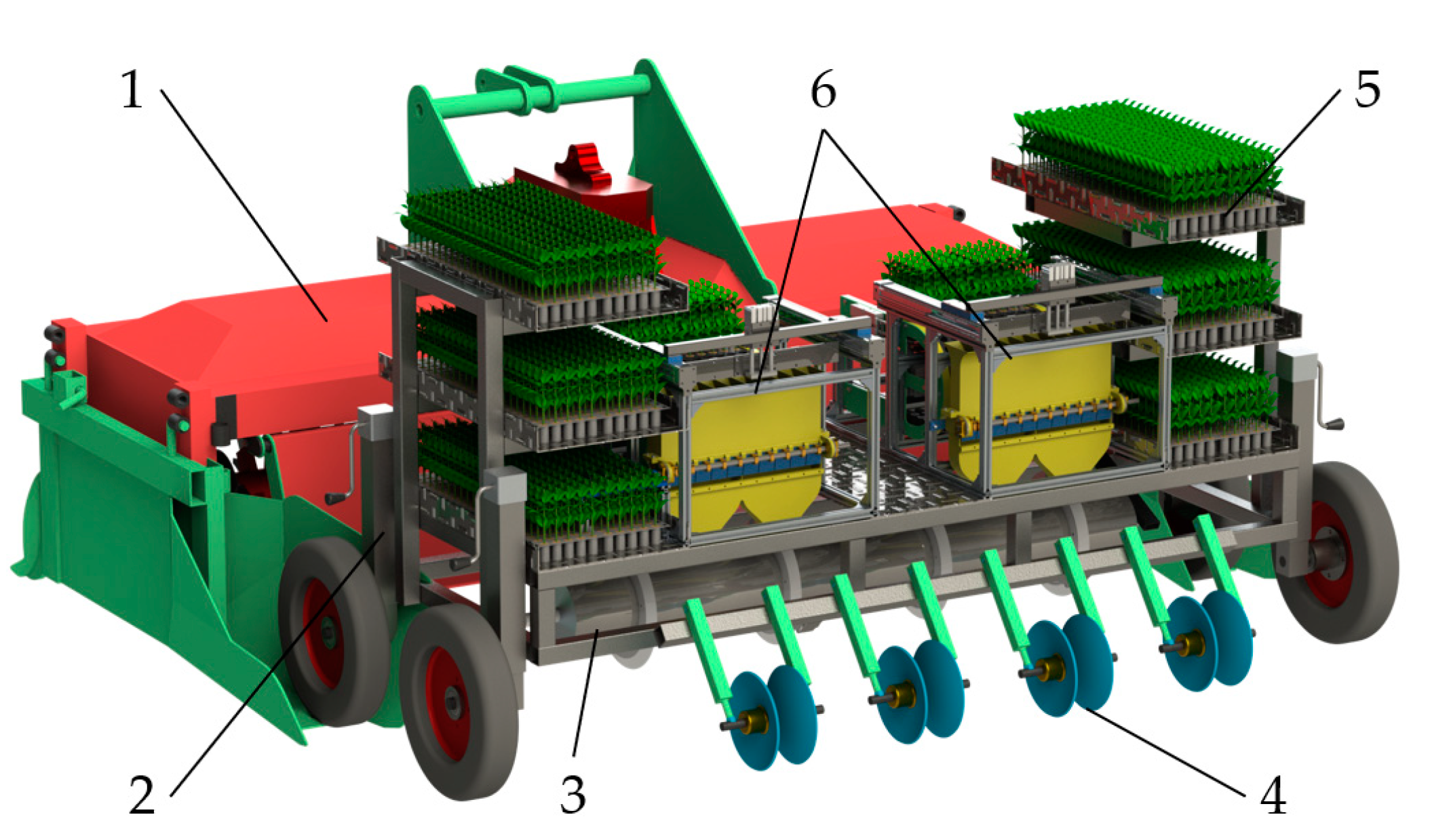
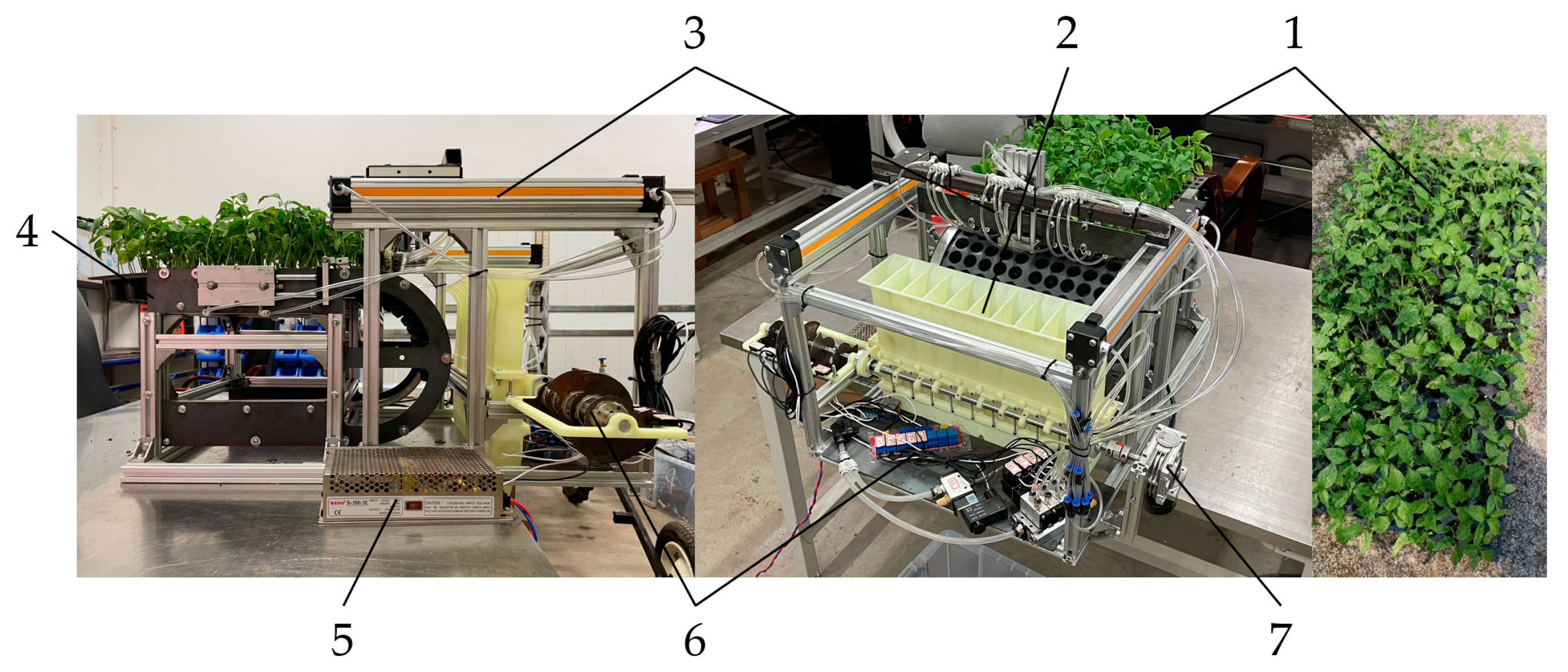
2.1.1. Supporting Transplanting Machinery

The ideal supporting transplanting machine for a fixed seedling cup intermittent automatic grouping feeding mechanism is a traction-type multi-row automatic rice transplanting machine. Taking the 2ZY-4 pepper pot seedling transplanting machine designed by Hunan Agricultural University as an example (Figure 1), the whole machine is mainly composed of a rotary tillage ridging device, height-adjustable frame, automatic seedling feeding device, rotary ditching device, soil covering device, seedling tray frame, and so on. The machine is connected to a tractor, which can realize the integrated operation of rotary tillage ridging transplanting and earthing. The automatic seedling feeding mechanism uses actuators such as compressed air to drive the cylinder and realize the automatic transportation of the pot tray, the whole row of pot seedlings, and the transportation of the whole row of pot seedlings. Finally, the pot seedlings are transported to the fixed seedling cup intermittent automatic grouping seedling feeding mechanism, and the mechanism is divided into two groups equally spaced between the transplanting mechanism, thereby realizing the high-speed automatic transportation of pot seedlings, and solving the problem of the low automatic transportation speed of pot seedlings.

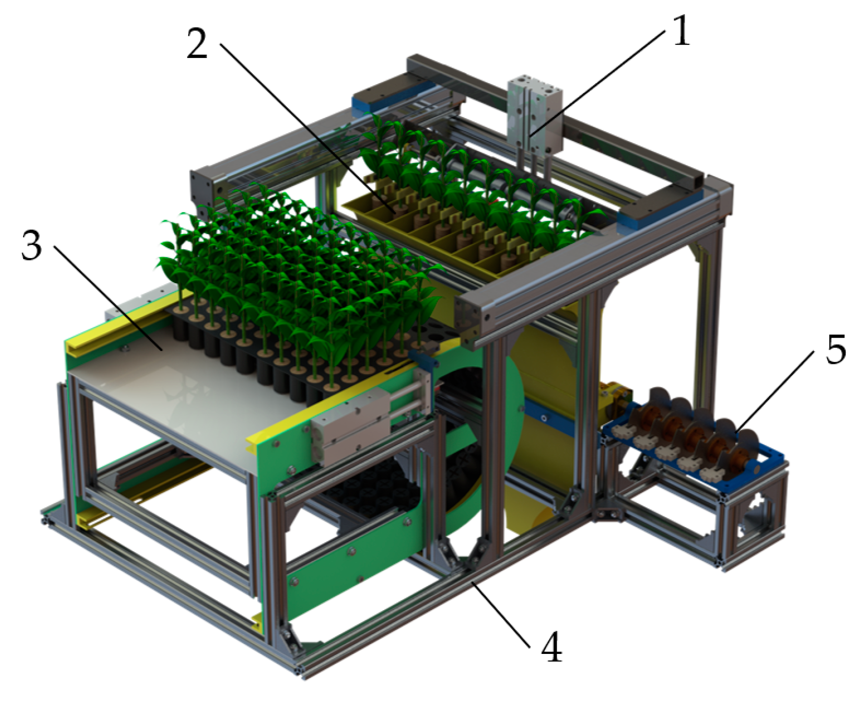
2.1.2. Automatic Seedling Feeding Device and Its Supporting Technology

The fixed seedling cup intermittent automatic grouping feeding mechanism is mainly applicable to the automatic seedling picking system of full-row automatic seedling pulling, such as the automatic seedling picking system of the 2ZY-4 pepper pot seedling transplanter shown in Figure 1 (Figure 2). It is mainly composed of a tray feeding mechanism, a pot seedling whole-row extraction and conveying mechanism, a fixed seedling cup intermittent automatic grouping seedling feeding mechanism, an electrical control system, and a rack. The tray feeding mechanism, which is responsible for the step-by-step supply of the tray, is mainly composed of a tray chute, pusher cylinder assembly, top seedling cylinder assembly, and so on. The seedling tray chute limits the movement of the seedling tray along the established trajectory, and the pushing plate cylinder assembly drives the seedling tray to move along the chute intermittently. The fixed seedling cup intermittent automatic grouping feeding mechanism is mainly applicable to the automatic seedling picking system of full-row automatic seedling pulling. The whole-row extraction and transportation of pot seedlings is composed of a transverse pneumatic slide rail, pneumatic seedling components, and other connecting parts. After the whole row of pot seedlings is extracted, they are transported to the fixed seedling cup intermittent automatic grouping seedling feeding mechanism.
Taking the Amerco Rishen series D220P vegetable tray as an example, the tray size (length × width × height) is 632 mm × 215 mm × 35 mm, 10 plants per row, 22 rows in total, and 220 plants per tray. The tray can bend at a large angle, and the limit of the bending radius Rmin is about 150 mm. As shown in Figure 3, the pneumatic seedling picking component is used in the whole row of the seedling picking and conveying mechanism. Before the bowl plate enters the bending point, the whole row of seedlings is grabbed, and the seedlings are pulled up. When the whole row of seedlings is pulled up, the interval length is W1, corresponding to the width of the seedling tray. After the seedlings are pulled out, they move to the seedling dropping mechanism and gradually extend the interval length to W2, corresponding to the width of the seedling dropping mechanism, thus disrupting the interlacing of the seedling leaves and preventing the seedlings from hanging on the spacer between each seedling tube within the seedling tray when the whole row of seedlings is dropped.

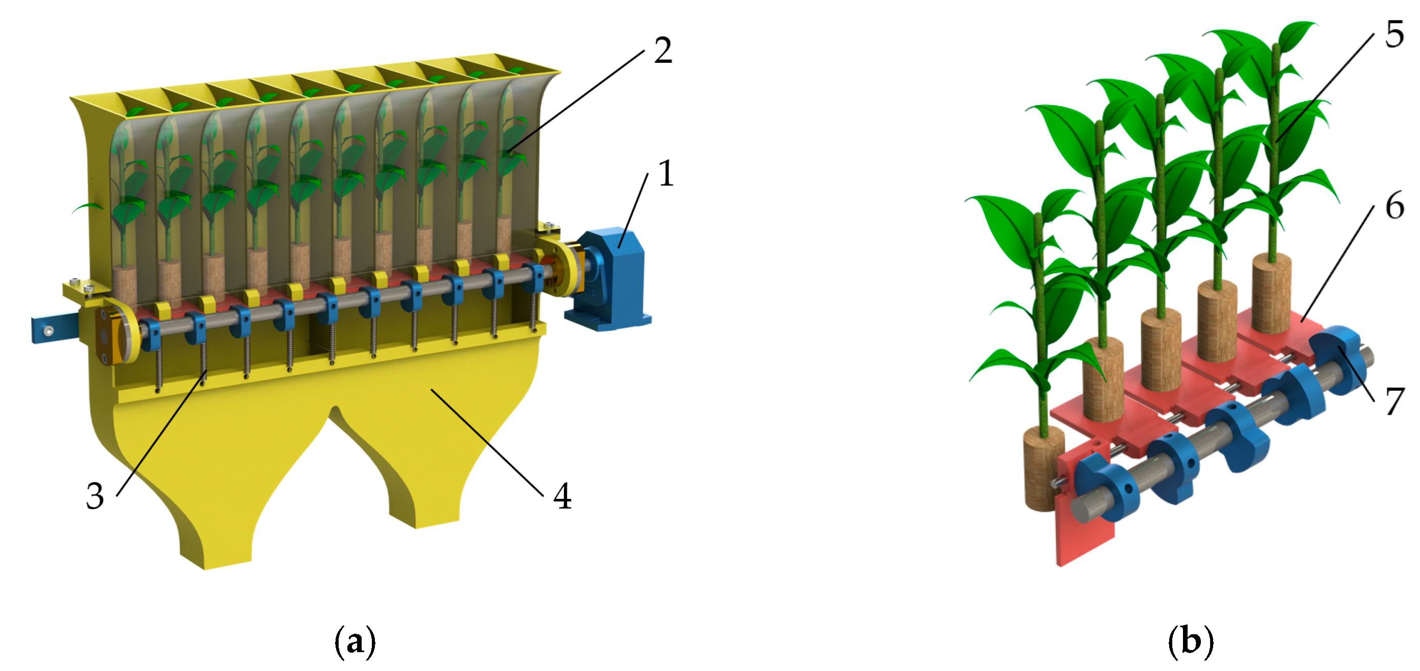
2.1.3. Interval Seedling Dropping Mechanism and Principle

Figure 4a shows the schematic diagram of the interval seedling dropping mechanism. To facilitate the introduction of the seedlings, the seedling separating cup is handled in a semi-transparent way. The intermittent opening component is composed of a driving cam, a cam driving shaft, a spring, and a seedling carrying plate. The whole row of pot seedlings falls into the separated seedling cups and is carried by the seedling carrying plate that can be rotated along the installation shaft and is horizontally and normally closed under the action of a spring. Figure 4b shows the principle of the interval seedling dropping mechanism. When the convex part of the driving cam contacts the seedling plate, the seedling plate gradually rotates to the vertical open state and remains that way for a period of time. During this time, the pot seedlings lose their support, fall by gravity, and enter the lower planting mechanism or planting groove along the seedling dropping cylinder. After the convex part is turned open, the seedling plate is restored to the horizontal closed state under the action of the spring, thus waiting for the next seedling. By staggering the drive cams, the seedling plate spacing in different positions can be opened, and then the potted seedling spacing in other seedling cups can be lowered.

2.1.4. Operation Process Analysis

The seedling dropping process of the seedling dropping mechanism is shown in Figure 5. Figure 5a is a schematic diagram of the sequence of seedling dropping at each position during the machine advancement, symmetrical from outside to inside and left to right.
The positions in the seedling separating cylinder are numbered from left to right as No. 1 to 10 positions, V is the forward speed of the machine, Si is the dropping process of the seedlings at different positions during the forward process, and the dotted line is the dropping trajectory of the seedlings at the corresponding positions. For example, S1 is a schematic diagram of the dropping process of pot seedlings in two positions, namely No. 1 and No. 10. The dropping trajectory is a combination of the dropping movement of pot seedlings along the inner wall of the seedling dropping cylinder and the uniform forward movement of the machine. The dropping movement of pot seedlings along the inner wall of the seedling dropping cylinder at each position is shown in Figure 5b. Obviously, the trajectory of the potted seedlings at each position is not the same due to the principle of dropping seedlings from the drop tube, resulting in an unequal time from the potted seedlings’ drop position to the planting position at each position, and the longer the drop trajectory, the longer the time required to drop seedlings.

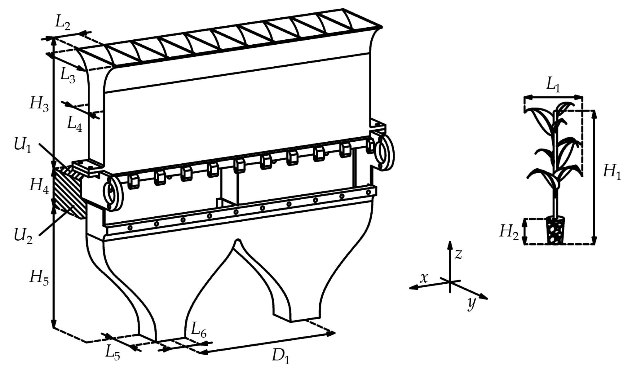
2.2. Design of Key Components

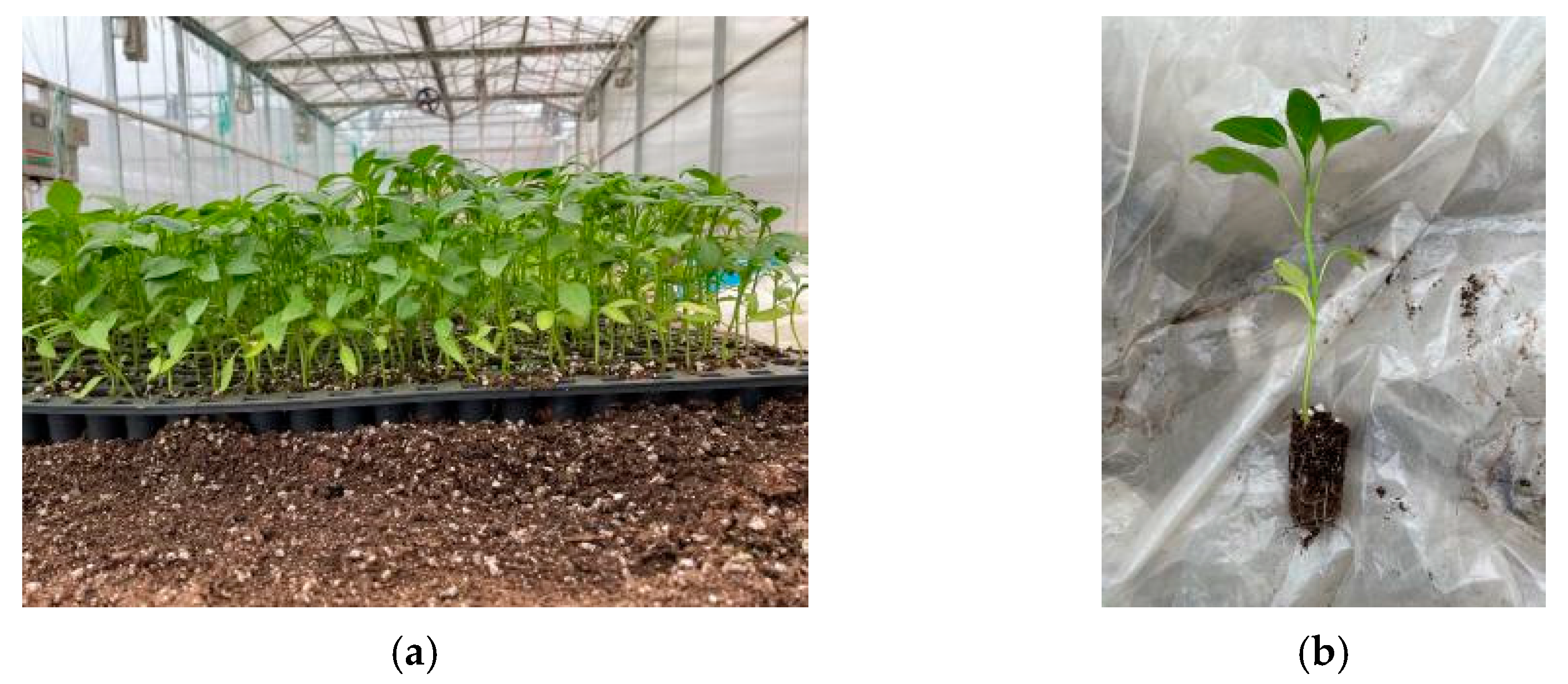
2.2.1. Determination of Material Characteristics of Pot Seedlings

Potted seedlings were the operation object of the research device in this paper, and its material characteristics were the basis for the design and the parameter analysis of the key components. “Xingshu 215” pepper pot seedlings cultivated by a vegetable seedling tray were selected (Figure 6). The seedlings were grown from 1 July to 10 August 2022 at an age of 40 days. The substrate of the seedlings was nutrient soil with coconut coir, peat, and perlite as the main components.
Twenty randomly selected potted seedlings were tested for material characteristics. The measuring tools were a Shanghai Lichen electronic analytical balance (model: JT1003D, measurement accuracy: 1 mg), a deli digital vernier caliper (model: DL91200, measurement accuracy: 0.1 mm), and a Xinghua Youke soil moisture meter (model: JK-100F, resolution: 0.1%). The average height H1 of the pot seedlings (including the pot body) was 138.4 mm, the average maximum leaf expansion was L1 = 86.4 mm, the average weight was 10.8 g, and the average water content of the pot body was 34.1%.

2.2.2. Seedling Cylinder

A seedling picking cylinder and seedling dropping cylinder are the main components of seedling caching and seedling launching, and their sizes are the key to the seedling dropping process and the volume of the whole machine. To avoid sticking seedlings, blocking the cylinder and intermittent seedling dropping during seedling drop, and to reduce the machine volume and the distance of the horizontal dispersing pneumatic seedling picking and launching device, the size of the seedling cylinder should be as small as possible to meet the requirements of free seedling dropping. Therefore, to make the device symmetrical, the overall width of the device should be related to the planting spacing. The main dimensions of the seedling separating cylinder and seedling dropping cylinder (Figure 7) should satisfy the following relation:
{ 10 L 2 = 2 D 1 L 2 = L 4 = L 5 = 0.8 L 1 L 3 = 2 L 2 L 5 > 1.2 H 2 L 6 = 0.8 D 2 H 3 = H 5 = H 1 H 4 = L 4
where D1 is the required row spacing for planting operations (200 mm); D2 is the planting ditch width (40 mm); L1 is the average maximum leaf expansion amplitude of pot seedlings (rounded to 100 mm); L2 is the transverse length of the single-chamber opening of the seedling cylinder (40 mm); L3 is the longitudinal length of the seedling cylinder compartment opening (80 mm); L4 is the minimum longitudinal length of the seedling separator (40 mm); L5 is the longitudinal length of the bottom opening of the seedling cylinder (40 mm); L6 is the transverse length of the bottom opening of the seedling cylinder (40 mm); H1 is the average height of the pot seedlings (including the pot body), rounded to 150 mm; H2 is the average height of the pot seedlings with a hole height of 33 mm; H3 is the distance between the top of the seedling cylinder and the plane U1 where the horizontal state of the seedling plate is located, 150 mm; and H4 is the plane U2 in the rotating area of the seedling carrying plate, which is an unsafe area. If the potted seedling falls through the area, the seedling carrying plate rotates and there is a risk of seedling jamming, this being 40 mm. H5 is the height of the safe area for the dropping of the pot seedlings in the seedling cylinder, 150 mm, and H6 is the height of the vertical area of the dropping mouth, 50 mm.

2.2.3. Drive Cam

A drive cam was the key component in driving the rotation of the seedling plate, and its profile curve was divided into a horizontal section and a vertical section, corresponding to the two states of the seedling plate, and the corresponding center angles are α1 and α2, respectively, as shown in Figure 8. An installation auxiliary plane was also designed in the horizontal section to facilitate the cam installation to be adjusted the installation angle with an inclinometer.
Assuming that the height of the pot seedling (including the pot body) is h0 and the length of the seedling plate is d0, the minimum time for a pot seedling to complete a safe fall is
t min = 2 ( h 0 + d 0 ) g
The rotation angular velocity of the drive cam is ω0, then
α 1 min = ω 0 t min
Considering the influence of friction resistance between the blade and the inner wall of the seedling cylinder in the process of dropping seedlings in pots, the actual dropping acceleration is less than gravity acceleration g. Therefore, the corresponding circular angle α1 of the horizontal section arc should be greater than α1min. The actual value was 60° after calculation with a rotational angular speed of 180°/s and the corresponding planting speed of 150 plants/(min · row).

2.3. Seedling Dropping Process Segmentation

Taking the pot seedling at the No. 1 position as the research object, its dropping process could be divided into the following four stages: (1) after dropping off from the seedling tray, it falls freely from position A to position B, and a collision occurs at position B (Figure 9a); (2) after the collision, the pot seedling is toppled and slid to position C along position B on the inner wall of the seedling cylinder (Figure 9b); (3) after the pot seedling reaches position C, it loses the support of the inner wall of the seedling separating cylinder and carries out an oblique launching motion and collides with point D of the inner wall of the seedling separating cylinder on the opposite side (Figure 9c); (4) the pot seedling continues to fall after the collision at position D. During the dropping process, the leaves of the pot seedling are constrained by the position of the dropping mouth and the seedlings are adjusted to fall vertically until reaching the lower planting tank.
During the dropping process, the seedling dropping cylinder should have the following effective constraints on the pot seedlings: (1) During the dumping process, after the collision between the potted seedlings and the inner wall of the dropping seedling tube, it should be ensured that the dumping direction of the seedlings is the direction of the inner wall on the same side, not the opposite side, otherwise, the seedlings will be planted backward or will cross the dropping mouth, causing a blockage; (2) The oblique pushing motion of potted seedlings starting from point C should collide with the opposite wall of the seedling tube and change the direction of the seedling movement speed by collision. If there is no collision, the seedling will fall out of the seedling cylinder at a large oblique speed, deviating from the direction of the planting ditch below, thereby resulting in a decrease in the planting accuracy; (3) The dropping seedling mouth should form an effective constraint on the seedling leaves during the dropping process after the second collision of the pot seedlings. By this constraint, the seedlings are adjusted to the vertical dropping state. Without such a constraint, the seedlings would maintain an inclined rate of descent after the collision, which would also deviate from the direction of the planting trench and reduce the planting accuracy.

2.3.1. Kinematics Analysis of Seedling Separation Process

The dropping motion process of pot seedlings at each position is not consistent. For example, the pot seedlings at the No. 1, 2, 4, and 5 positions have segmented trajectories, while the pot seedlings at position No. 3 have straight trajectories. Neglecting the air resistance and the friction between the blade and the inner wall of the seedling cylinder during the dropping of the pot seedling at position No. 3, it can be regarded as a free-dropping motion with an initial velocity of 0 m/s. The starting point of the dropping seedling is the plane where the seedling carrying plate is located, and the end point is the seedling planting groove. Since the No. 1 and 2 positions are symmetrical with the No. 4 and 5 positions, the dropping trajectories of the No. 1 and 2 positions are similar. Therefore, to simplify the analysis process, the kinematic analysis was performed under a segmented trajectory with position No. 1 as an example, and for the linear trajectory, the No. 3 position was analyzed separately.
As shown in Figure 9a, the pot seedling at the No. 1 position falls freely from point A to point B, with a dropping height of LAB and a unilateral deformation of ε1. The relative velocity of the pot seedling before the collision is v1, and the relative velocity of the pot seedling after the collision is v2. The vertical upward direction is the positive direction, and in the vertical direction, according to the momentum theorem, the following equation can be obtained
( F 1 m g ) Δ t 1 = ( m v 2 cos α ) ( m v 1 )
where F1 is the impact force on the body of the pot seedling, N; m is the mass of the pot seedling, g; Δt1 is the collision time, s; v1 is the relative velocity of pot seedlings before collision with point B, m/s; v2 is the relative velocity of pot seedlings after the collision with point B, m/s; and α is the sliding angle of the pot seedling, °.
The collision force can be obtained as follows:
F 1 = m ( v 1 v 2 cos α Δ t 1 + g )
For the convenience of calculation, the air resistance of the pot seedling when sliding from point A to point B and the friction between the pot seedling blade and the inner wall of the seedling cylinder were neglected. The pot seedling and the slideway were approximately subjected to a free-dropping motion before the collision. That is, the velocity of the pot seedling before the collision is
v 1 = 2 g L A B
As shown in Figure 9b, after the collision, the pot seedlings slide along the inner wall of the seedling cylinder, with the center of the weight of the canister as the study point. During the sliding process, the pot seedlings are subjected to a friction force f1(x,y), support force N1(x,y), and their gravity G. The planting requires the potted seedling to fall to the ground to maintain a stable state and to rely only on the gravity of the potted seedling to pull it from the sliding starting point to the planted seedling. In the process from position B to position C, the friction f1(x,y) of the pot seedling performs negative work, and the pot seedling performs a variable motion in the system. According to the kinetic energy theorem, the following equation can be obtained
m g L B C cos α L B C f ( x , y ) d s = 1 2 m v 3 2 1 2 m v 2 2
where LBC is the path length from point B to point C, mm; f(x,y) is the functional relation of the friction between the potted seedling and the inner wall of the seedling dropping cylinder, N; and v3 is the relative velocity of the pot seedling sliding to point C, m/s.
According to Equation (7), the following equation can be obtained
v 2 = v 3 2 2 g L B C cos α + 2 L B C f ( x , y ) d s m
As shown in Figure 9c, after the pot seedling reaches point C, there is an oblique launching angle with an initial velocity of v3 and an oblique launching angle of α. In this process, it is only affected by its own gravity until it collides with point D on the opposite side of the seedling cylinder wall, and the unilateral deformation caused by the collision is ε2. According to the oblique launching motion formula, the following equation can be obtained
{ v 3 cos α Δ t 2 + 1 2 g ( Δ t 2 ) 2 = H 6 v 3 sin α Δ t 2 = L 6
where Δt2 is the projectile motion time, s.
According to the kinetic energy theorem, the following equation can be obtained
1 2 m v 3 2 + m g L C D cos α = 1 2 m v 4 2
where v4 is the relative velocity of pot seedlings before the collision of D point, m/s, and LCD is the path length from point C to point D, mm.
According to Equation (9), the relative velocity of the pot seedling sliding to point C can be obtained as follows:
v 3 = g L 6 2 2 ( H 6 L 6 tan α ) sin 2 α
Substituting Equation (11) into Equation (10), the velocity before the collision between the pot seedling and point D can be obtained
v 4 = ( g L 6 2 2 ( H 6 L 6 tan α ) sin 2 α ) 2 g L C D cos α
The relative velocity of the pot seedling after collision can be obtained by substituting Equation (11) into Equation (8)
v 2 = ( g L 6 2 2 ( H 6 L 6 tan α ) sin 2 α ) 2 g L B C cos α + 2 L B C f ( x , y ) d s m
As shown in Figure 9d, the pot seedling continues to fall after colliding with point D, during which the pot seedling blade is subjected to the supporting force of friction at the dropping mouth: f2(x, y) and N2(x, y). Under the action of this supporting force, the dropping posture of the pot seedling gradually changes downward and vertically until it falls to the position of the planting groove E. As the cans collide at point D, the angle between the velocity direction and the collision surface is small, the energy loss in the collision process is neglected, and the velocity direction of the potted seedlings remains constant. The process was thus simplified to a free dropping motion with initial velocity v4.

2.3.2. Analysis of Dropping Seedling Duration

The dropping process of pot seedlings starts from the rotation of the seedling plate to the end of the pot seedling dropping into the seedling planting groove. The length of time from the start of the seedling plate to the start of the potted plant is called the start time, which is independent of the position of the potted plant. According to the previous analysis, the dropping trajectories of pot seedlings at the No. 1, No. 2, No. 4, and No. 5 positions are similar. Simplifying the dropping process of the potted seedlings at the No. 3 position as a free dropping motion, the dropping duration ti of the pot seedlings at each position can be divided into
{ t i = t Q + t i A B + t i B C + t i C D + t i D E   ( i = 1 , 2 , 4 , 5 ) t i = t Q + t i A E ( i = 3 )
where tQ is the time from the onset of the rotation of the seedling plate to the start of the dropping of the pot seedling, s; tiAB is the dropping duration from Bi to Ci, s; tiBC is the dropping duration of the pot seedlings from Bi to Ci, s; tiCD is the dropping duration of the pot seedlings from Ci to Di, s; tiDE is the dropping duration of the pot seedlings from Di to Ei, s; and tiAE is the dropping duration of the pot seedlings from Ai to Ei, s;
The drop duration was analyzed using the potted seedlings at the No. 1 position as an example. After the seedling carrying plate is activated, the pot seedlings begin to fall after a time tQ. The time from point A to point B is
t 1 A B = 2 L A B cos α g
When analyzing the force of the pot seedlings in the BC section in Figure 9b, the motion in the BC section can be simplified to a uniform variable motion with an initial velocity of v2 and a final velocity of v3, and the time from point B to point C is
t 1 B C = 2 L B C v 2 + v 3
The duration of the oblique projectile motion from point C to point D is
t 1 C D = v 3 cos α + ( v 3 cos α ) 2 2 g L C D cos α g
The approximate free-dropping motion duration from point D to point E is
t 1 D E = 2 L D E g
The dropping duration of pot seedlings in each time period can be added to obtain the total dropping time of pot seedlings at the No. 1 position as follows:
t 1 = t Q + 2 L A B cos α g + 2 L B C v 2 + v 3 + v 3 cos α + ( v 3 cos α ) 2 2 g L C D cos α g + 2 L D E g
Since the No. 2 position is only different from the No. 1 position in the collision position, the total dropping duration of the pot seedlings at the No. 2 position can be similarly obtained as follows:
t 1 = t Q + 2 L A B cos α g + 2 L B C v 2 + v 3 + v 3 cos α + ( v 3 cos α ) 2 2 g L C D cos α g + 2 L D E g
The pot seedlings at the No. 3 position directly fall vertically from the cavity of the seedling separating cylinder, and the total dropping seedling duration is
t 3 = t Q + 2 L A E g
As the left and right seedling separating cylinders are symmetrically arranged, the total time for the pot seedlings to fall at each position is t1 = t5, t2 = t4, and t1 = t5 > t2 = t4 > t3.

2.4. Relationship between the Installation Angle of the Drive Cam and the Dropping Seedling Duration

To compensate for the time difference in completing the fall of the potted seedlings at the different positions, it was necessary to set the compensation angle γi based on the angular difference arrangement of the drive cam, and then make the pot seedlings at different positions fall into the planting seedling groove at the same time interval by opening the seedling plate in advance or backward. Based on the installation position of the drive cam at the No. 1 position, the installation angle of other drive cams on the driving shaft is βi, the rotational angular velocity of the cam driving shaft is ω, and the starting rotation time of the seedling carrying plate at the No. 1 position is time 0, so the dropping seedling duration at the No. 1 position in the seedling receiving cylinder can be obtained
T i = β i ω + t i
With a constant forward speed of machine V, the time difference between the two adjacent pot seedlings determines the plant spacing. Let the position of the machine at time 0 be 0, then the landing position of the pot seedling at the No. 1 position in the seedling cylinder is
D i = T i V = ( β i ω + t i ) V
If the drive cams are arranged at equal angular intervals, then
[ β 1 β 2 β 3 β 4 β 5 ] = [ 0 ° 72 ° 144 ° 216 ° 288 ° ]
Taking the dropping duration t1 of the pot seedlings at the No. 1 position as the standard, the difference in the dropping duration of pot seedlings between the No. 1 position and the No. 2 position is
Δ t 12 = t 1 t 2 > 0
The installation compensation angle of the drive cam at the No. 2 position is
γ 2 = ω Δ t 12 = ω ( t 1 t 2 )
The installation angle of the drive cam at the No. 2 position is
β 2 = 72 ° + γ 2 = 72 ° + ω ( t 1 t 2 )
Similarly, the installation angles of the drive cams at the No. 3, 4, and 5 positions can be obtained
[ β 3 β 4 β 5 ] = [ 144 ° + ω ( t 1 t 3 ) 216 ° + ω ( t 1 t 4 ) 288 ° + ω ( t 1 t 5 ) ]
After measuring the dropping duration of the pot seedlings at each position, the installation angles of the drive cam at the No. 2–5 positions can be obtained by solving Equations (27) and (28) based on the dropping duration of pot seedlings at the No. 1 position.

3. Parameter Optimization and Performance Test

3.1. Net Dropping Seedling Duration Measurement Test

The dropping seedling duration ti includes the time tQ from the start of the rotation of the seedling plate to the start of the dropping process of the pot seedling and the dropping process durations of the pot seedlings are tiAB, tiBC, tiCD, and tIde. Since tQ is influenced by the opening speed of the seedling plate and the maximum static friction angle between the pot seedling and the seedling plate, the opening speed of the seedling plate is determined by the planting rate. The higher the planting rate, the faster the opening speed of the corresponding seedling plate. Therefore, when measuring the duration of seedling dropping, the opening process of the seedling plates should be ignored, and the duration of seedling dropping on the horizontal plane of the seedling plates should be measured directly to increase the applicability of test results under different seeding rate conditions. Therefore, the net dropping seedling duration is
t i j = t i A B + t i B C + t i C D + t i D E
Because the duration tQ from the start of the rotation of the seedling plate to the start of the dropping was equal at each position under the same planting rate, the calculation equation established above for the installation angle of the drive cam did not fail.

3.1.1. Test Conditions

The automatic seedling feeding device shown in Figure 10 was developed to measure the net seedling dropping duration, which was powered by a 24 V DC power supply to drive the motor, air compressor, and pneumatic control system. The motor drove the operation of the batch seedling launching mechanism; the air compressor provided compressed air for the pneumatic seedling clamp and each expansion cylinder; and the pneumatic control system included photoelectric switches, solenoid valves, and other components, which were used to control the pneumatic components to complete the specified action according to the timing. The pot seedlings used in the test were “Xingshu 215” pepper pot seedlings with a seedling age of 35 days. The seedling growth was from 20 July to 25 August 2022, and 20 pot seedlings were randomly selected for the material characteristics test. The average height of the pot seedlings (including the pot body) was 141.5 mm, the average maximum leaf expansion was 93.1 mm, the average weight was 12.2 g, and the average water content of the pot body was 42.5%.

3.1.2. Measurement Method

The nursery board was opened, and the potted seedlings were held with both hands so that the lower end of the pot was flush with the initial drop height, and the potted seedlings were then released to let them fall freely. During this period, the potted seedlings were filmed using high-speed camera equipment at 240 frames/second. After the shooting was completed, the generated video was 30 frames/s, which was eight times slower. After exporting the video, video clip software was used to process the video. The video start point was moved to the frame where the pot seedlings started to fall (Figure 11a), and the video end was moved to the frame where the pot seedlings completely fell out of the seedling cylinder (Figure 11b), and the video duration Ui was obtained. Equation (30) was used to calculate the net dropping duration tj of the pot seedlings at each position. The theoretical calculation accuracy of this method was 0.0047 s, which was the corresponding time length of one frame at the shooting rate of 240 frames/s, that is, 0.0047 s. In the actual calculation process, the counting accuracy was 0.01 s.
t j = U i 8
Ten seedling tests were carried out at each position, and a total of fifty tests were performed at five positions. After the trials were completed, the average value, standard deviation, and variation coefficient of the seedling dropping duration were calculated according to Equation (30).

3.1.3. Experimental Results and Analysis

The test results are shown in Table 1, and according to Table 1, the following conclusion were drawn:
  • Due to the differences between the individual bot seedlings, the net seedling dropping duration of different seedlings at the same position was inconsistent and fluctuated within a certain range and was mainly affected by the state of the pot. Some potted seedlings were broken during the pick-up process, and the energy loss during collision and friction was different, which affected the drop rate. The pot seedlings of the No. 1, 2, 4, and 5 positions were in contact with the inner wall of the seedling dropping cylinder, and there were more uncertainties in the seedling dropping process, so the coefficient of variation was larger. The potted seedlings at the No. 3 position had less uncertainty in the drop process, and the coefficient of variation was smaller.
  • The dropping duration of the pot seedlings at the No. 1, 2, 4, and 5 positions was similar, with the average drop duration being about 0.37 s, and the average net dropping duration at the No. 3 position was 0.32 s. The reason for the large difference at the No. 3 position was that there was almost no contact with the inner wall of the seedling dropping cylinder during the seedling dropping process, while collision and friction occurred at the inner wall of the drop tube during the dropping process at the other positions resulting in energy loss and a longer drop trajectory than at the No. 3 position.
  • The dropping trajectories of the pot seedlings at the No. 1, 2, 4, and 5 positions were different, but the net dropping duration was similar, indicating that the collision height, collision angle and friction distance in the two dropping trajectories had little effect on the energy loss during the dropping process under the experimental conditions.

3.2. Optimization Results and Verification Test of Drive Cam Installation Angle

3.2.1. Optimum Results

Referring to JB/T 10291-2013 Dry Land Planting Machinery, the planting frequency of the high-speed transplanter was greater than or equal to 90 plants/(min · row), the rotation angular velocity of the drive cam ω was set to 120°/s, and the corresponding planting frequency was 100 plants/(min · row). Since the net seedling dropping duration of the pot seedlings at the No. 1, 2, 4, and 5 positions was similar, no optimization was required. The net seedling dropping duration of the No. 3 position was 0.32 s, and the average net seedling dropping time at the other positions was 0.37 s. Substituting this into Equation (28), the installation compensation angle was calculated to be 6° after offsetting tQ. To sum up, to make the potted seedlings at each position fall at the same time interval, the installation angles of the driver at the No. 1~5 positions should be 0°, 72°, 150°, 216°, and 288°, respectively.

3.2.2. Test Conditions

The drive cam was installed according to the drive cam installation angle obtained above. To guarantee the accuracy of the installation angle and avoid cumulative errors in the installation process, all the drive cams were installed with the No. 1 position as the standard. The specific installation methods were as follows:
  • Calibrate the electronic slope meter, set five drive cams into the drive shaft, and lock the drive cam at the No. 1 position to prevent it from rotating relative to the drive shaft, and install the drive shaft to the bearing seat;
  • Adjust the angle of the drive shaft by pressing a 3 mm thick steel plate against the mounting aid plane on the cams, and then observe the electronic gradiometer attached to the plate. When the gradiometer reading is 0°, it indicates that the drive cam at the No. 1 position is in a horizontal state, and at this time, a locking ring should be installed at both ends of the drive shaft to fix it in order to adjust the driving shaft to the horizontal reference position;
  • Install the auxiliary plane by making the steel plate close to the drive cam at the No. 2 position, adjust the position of the drive cam, and observe the gradiometer reading. When the reading reaches 72°, it means that the drive cam at the No. 2 position has been rotated to the predefined installation position, and at this time, it is fixed to the drive shaft through the top wire locking cam;
  • Repeat step (3) for the drive cams at the No. 3–5 positions to complete the installation of all the drive cams. It is particularly important to note that the above installation method is in an ideal state. In the actual installation operation, since it is performed manually and the installation auxiliary plane of the drive cam is small, the installation results will inevitably have errors, and after repeated debugging, the installation errors can be controlled to within ±1°.
The seedlings used in the test were the same as the batch of seedlings used in the net seedling drip measurement test.

3.2.3. Test Method

Before the test, the motor speed was adjusted to 120°/s using a photoelectric speed sensor (model: TA8146A, minimum measurement speed: 2.5 r/min, resolution: 0.1 r/min) and the built-in controller of the motor. The initial state of the drive cam was the rigid contact position between the cam at the No. 1 position and the seedling plate, and all the seedling plates were horizontal. The pot seedlings were weighed to obtain the mass mbi before dropping the seedlings. To accurately measure the matrix loss caused by the collision between the pot seedlings and the inner wall of the seedling cylinder during the seedling dropping process, the height of the seedling outlet from the ground should be as small as possible to reduce the matrix loss caused by the secondary collision with the ground. The average height of the bot seedlings was set to 200 mm.
When the test began, the motor was started, the motor was activated to drive the cams to rotate at a uniform speed, and then the potted seedlings started to fall. High-speed photography equipment was used to shoot the seedling dropping process at a frame rate of 240 frames/s.
After the test was completed, the generated 30 frames/s of slow-motion video were processed to obtain the duration t1. When the pot seedlings at the No. 1 position reached the designated seedling dropping position, and the time interval between the pot seedlings at the No. 2~5 positions and the previous plant when they reached the designated position was Ti,i+1 (i = 1, 2, 3, 4), the pot seedlings after dropping were weighed to obtain the mass mai.

3.2.4. Testing Indexes

The seedling dropping success rate Y1, the variation coefficient of the seedling dropping interval Y2, and matrix damage rate Y3 were selected as the test indexes. The seedling dropping success rate Y1 was used to measure the passing ability of the pot seedlings in the seedling cylinder and whether the pot seedlings were stuck during the dropping process. The variation coefficient of seedling dropping interval Y2 was used to measure the uniformity of the seedling dropping interval at the different positions, so it was an important index to judge the uniformity of the actual planting spacing in the later stages. The matrix damage rate Y3 calculates the average mass of the same batch of pot seedlings before and after dropping and determines the collision between the pot seedlings and the inner wall of the pot during the dropping process.
The calculation method of each test index was as follows
Y 1 = n 2 n 1 × 100 %
Y 3 = 1 m a i ¯ m b i ¯ ( i = 1 , 2 , 3 , 4 , 5 )

3.2.5. Test Results and Analysis

The test data and test index calculation results are shown in Table 2.
  • Analysis of the success rate of seedling dropping: According to the data in the table, the success rate of falling seedlings in five groups of experiments was 100%, i.e., all the potted seedlings could fall smoothly without the phenomenon of stuck seedlings. The results showed that the size design of the seedling separating cylinder and the seedling dropping cylinder was designed to meet the requirements of smooth dropping of the pot seedlings under the premise of a compact structure.
  • Analysis of the seedling dropping interval and variation coefficient: According to the data in the table, due to the influence of the difference between the individual seedlings, the seedling dropping duration at the same position still fluctuated, which in turn caused the dropping time interval between the seedlings to change randomly. In the five groups of experiments, the time interval of dropping the seedlings was relatively stable, with a maximum coefficient of variation of 7.29%, a minimum coefficient of variation of 5.38%, and an average coefficient of variation of 6.25%, with a small fluctuation range.
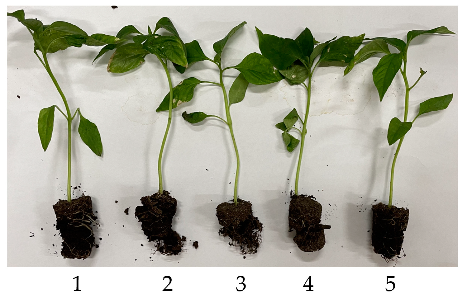
  • Analysis of the matrix damage rate: The matrix damage rate is an important index affecting planting quality and subsequent growth of pot seedlings. In the experiment, the minimum loss rate of the pot seedlings was 7.34% in group 4, and the maximum was 10.75% in group 3. The average loss rate of the pot seedlings was 9.01%, which was less than 10%. The observation of the test process revealed that the loss rate of the potted seedlings was related to the state of the potted plants themselves. Some pot seedlings were relatively intact before seedling dropping, and only small particles were lost after seedling dropping (pot seedlings at positions No. 1, 4, and 5 in Figure 12), while some potted seedlings had a greater loss of the matrix and loose cans during the emergence and harvesting stages, which led to a greater loss of mass during collision (pot seedlings at the No. 2 and 3 positions in Figure 12).

3.3. Experiment on Stability of Seedling Dropping Duration under Multi-Planting Frequency

During the initial debugging process, it was found that when the seedling plate was opened slowly, the potted seedlings were affected by static friction between the pot and the seedling plate and were stationary until they rotated to the maximum static friction angle and were also affected by dynamic friction after sliding. The friction coefficient between the pot seedling body and the seedling plate was related to the integrity of the pot body, and the duration of the dropping process was also correlated with the sliding distance of the pot seedling. It was difficult to quantitatively analyze the integrity of the potted seedlings and potted bodies as well as the randomness of their placement on the seedling plate after seedling removal. Therefore, in this paper, starting from the opening speed of the seedling plate, the sliding process between the pot seedling and the seedling plate was analyzed to determine what speed had an obvious impact on the total seedling dropping duration. Therefore, subsequent planting operations should be avoided below this value.

3.3.1. Test Method

The rotational speed of the drive cam was changed by adjusting the rotational speed of the drive motor, and then the opening speed of the seedling carrying plate was changed, and the variations in the dropping duration of the pot seedlings under different rotational speeds were tested. Since the sliding process occurred before the pot seedlings fell, the test was only carried out at the No. 3 position, that is, only t3 was measured to avoid collision between the pot seedling body and the seedling cylinder wall.
The motor speed adjustment method was referred to the previous section, and after the speed adjustment was completed, the pot seedlings were loaded for the dropping seedling test. The speed adjustment range was 60°~150°/s, corresponding to the planting speed of 50–125 plants/(min · row). The adjustment range was grouped at an interval of 10°/s for a total of 10 groups, with 10 tests per group. The frame in which the seedling transport plate started to rotate was the starting frame, while the frame in which the pot seedlings were completely dislodged from the outlet was the ending frame. At the end of the experiment, the duration of seedling dropping at each speed was obtained using high-speed photographic video, and then the mean and coefficient of variation of the seedling dropping duration were calculated and compared.

3.3.2. Test Results and Analysis

The test results and the calculation of the variation coefficient are shown in Table 3.
The test results showed that:
  • When the drive motor speed was low (60°~80°/s, corresponding to a planting frequency of 50~67 plants/(min · row)), the coefficient of variation of the seedling dropping duration was larger. The main reason was that the frictional sliding process of the potted seedlings differed at the same seedling plate opening speed due to friction and the frictional sliding distance, and the difference had a large uncertainty, while the slower the opening speed, the larger the difference, which led to a large variation in the potted seedling dropping duration.
  • With the increase in the drive motor speed (90°~150°/s, corresponding to a planting frequency of 75~128 plants/(min · row)), the opening speed of the seedling carrying plate was accelerated, and the pot seedlings lost the support of the seedling carrying plate and fell in a short period of time. The difference in the sliding duration caused by individual differences in the pot seedlings was compressed, which reduced the uncertainty in the process of falling seedlings, and the duration of falling seedlings was stabilized.
  • By observing the test process, it was found that when the speed of the drive motor was large (140°~150°/s, corresponding to a planting frequency of 117~125 plants/(min · row)), although the coefficient of variation of the dropping seedling duration did not change significantly, the installation angle of the drive cam at each position was found to change to varying degrees after the test. Preliminary analysis indicated that the reason for this was that the effect of contact with the seedling carrier plate increased as the drive cam speed increased. Since the cam and drive shaft were fixed by a top wire, they could not withstand large impact loads. Therefore, the drive cam had a small angle offset during contact, and because of the difference in the installation tightness, the cam offset angles at each position were different. Moreover, as the test was only carried out at the No. 3 position, and no continuous drop test was performed at each position, thus the drop time caused by the change in the installation position of the drive cam could not be reflected.

3.4. Test Summary

Based on the above results of the seedling dropping performance bench test, although the mechanism did not carry out the field planting performance test with the ditching device, the tray feeding mechanism, the seedling taking and launching mechanisms, etc., with reference to the definition of the planting frequency of the high-speed transplanter in JB/T 10291-2013 Dry Land Planting Machinery, the seedling dropping mechanism studied in this paper carried out the bench seedling dropping test at the planting rate of 100 plants/(min · row), and the seedling dropping success rate was 100%. The average variation coefficient of the seedling dropping interval at the different positions was 6.25%, and the seedlings fell evenly. The average matrix damage rate was less than 10%, and the pot seedlings had no obvious damage. The seedling dropping mechanism had a good effect and could meet the requirements of uniform and low-loss seedling dropping in the operation. Under a planting frequency of 75–108 plants/(min · row), the uniform dropping seedling operation could be better completed. If higher planting requirements are needed, the installation method of the drive cam needs to be improved, or the tension of the tension spring to the seedling plate should be appropriately reduced to avoid a large angular displacement of the drive cam and the seedling plate due to the large impact at the moment of contact, which will affect the uniformity of the subsequent seedling dropping interval.

4. Conclusions

  • An intermittent automatic grouping seedling dropping mechanism based on a fixed seedling cup was designed. Then, a traction-based automatic pot seedling transplanting machine and automatic seedling feeding device were introduced. Later, the principle and operation process of the grouping seedling dropping mechanism were expounded. Finally, the structural parameters of the key components such as the seedling cylinder, the seedling dropping cylinder, and the drive cam were determined.
  • The collision process between the seedling substrate and the inner wall of the seedling cylinder during the seedling dropping process was analyzed. The dropping duration of the pot seedlings at each position was studied. The dropping trajectory of the two sides was longer than that of the middle position, and the collision loss with the inner wall of the seedling cylinder was large. The relationship between the installation angle of the drive cam at each position and the length of the seedling was analyzed, and the calculation equation between the cam rotation angle, the seedling dropping duration, and the cam installation angle was derived.
  • The dropping duration of the pot seedlings at the No. 1 to 5 positions was 0.36 s, 0.38 s, 0.32 s, 0.36 s, and 0.37 s, respectively. Only the No. 3 position was required to optimize the installation angle. With a planting frequency of 100 plants/(min · row) as the design target, the adjusted installation angles of the drive cam at the No. 1 to 5 positions were 0°, 72°, 150°, 216°, and 288°, respectively. The seedling success rate, seedling synchronization rate and substrate destruction rate of the cluster seedling mechanism were tested under a planting frequency of 100 plants/(min · row) by installing the cams with the optimized cam installation angle. The results revealed that the success rate of seedling dropping was 100%, the variation coefficient of the seedling dropping interval at the different positions was 6.25%, and the matrix damage rate was less than 10%. There were no stuck and injured seedlings, and the seedling dropping was uniform. The stability test of the seedling dropping time under various planting frequencies was carried out, and the test results showed that the mechanism could complete the uniform seedling dropping operation under the existing installation conditions at a planting frequency of 75~108 plants/(min · row).

5. Discussion

The intermittent automatic grouping mechanism of the fixed seedling cups studied in this paper is mainly used for grouping seedlings of whole rows of potted seedlings through mechanical control and adjusting the cam drive shaft speed to accommodate different seeding rates. In terms of the planting method of straight planting grooves, the mechanism could meet the operation requirements. Compared with an existing batch seedling falling device [19,20,21], the experimental prototype obtained from this study was smaller, more efficient, and suitable for more than four rows of planting operation. However, this research only carried out indoor prototype tests, and the actual effect on field planting is still unclear. Therefore, seedling pick-up trials with rice transplanters and subsequent field-based mechanical seeding studies with furrow openers and seedling pick-up launchers are needed.

Author Contributions

Conceptualization, B.C. and M.X.; methodology, B.C. and G.H.; software, B.C., validation, B.C. and G.H.; formal analysis, B.C. and G.H.; investigation, B.C. and G.H.; resources, B.C. and G.H.; data curation, B.C. and G.H.; writing—original draft preparation, B.C. and G.H.; writing—review and editing, S.S., M.X. and C.S.; visualization, B.C. and G.H.; supervision, S.S.; project administration, M.X. and C.S.; funding acquisition, M.X. and C.S. All authors have read and agreed to the published version of the manuscript.

Funding

This research was funded by National Key R&D Projects of China (2017YFD0700800), and Key R&D Program of Hunan Provincial Science and Technology Department (2019NK2141).

Institutional Review Board Statement

Not applicable.

Informed Consent Statement

Not applicable.

Data Availability Statement

All data are presented in this article in the form of figures and tables.

Acknowledgments

We sincerely thank the members of the project team and anonymous reviewer experts for their thoughtful review of this research and Jindu Zhou for her support during the conduct of the research.

Conflicts of Interest

The authors declare no conflict of interest.

References

  1. Shi, Q.; Liu, J.X.; Zeng, J.X.; Yao, S.B.; Zhao, C.Y.; Liu, Y.M. Optimization of the clamping trajectory of an automatic seedling fetching and throwing of a vegetable seedling transplanter. Trans. Chin. Soc. Agric. Mach. 2021, 42, 47–54. [Google Scholar] [CrossRef]
  2. Hu, F.; Guo, D.; Chen, C.R.; Yan, H.; Yin, W.Q.; Yu, H.M. Design and experiment on compound crank rocker double-row planting device of vegetable plug seedling up-film transplanter. Trans. Chin. Soc. Agric. Mach. 2021, 52, 62–69. [Google Scholar] [CrossRef]
  3. Xue, X.L.; Wang, L.; Xue, C.L.; Zhou, M.L.; Zhao, Y. Optimal design and experiment of longitudinal feeding-seedling device of potted seedling transplanter for upland field. Trans. Chin. Soc. Agric. Mach. 2020, 51, 76–84. [Google Scholar] [CrossRef]
  4. Hu, Q.L.; Yuan, J.C.; Li, X.Z.; Wang, L.; Zhang, Q.S.; Liao, Q.X. Design and experiment of two-way progressive seedling feeding for rape substrate transplanters. Trans. Chin. Soc. Agric. Mach. 2022, 53, 106–115. [Google Scholar] [CrossRef]
  5. Xie, S.Y.; Yang, S.H.; Liu, J.; Song, L.; Xie, Q.J.; Duan, T.Y. Development of the seedling taking and throwing device with oblique insertion and plug clipping for vegetable transplanters. Trans. Chin. Soc. Agric. Eng. 2020, 36, 1–10. [Google Scholar] [CrossRef]
  6. Xiao, M.T.; Xiao, S.X.; Chen, B.; Sun, S.L.; Xiong, L. Design and experiment of horizontal push seedling transplanting mechanism for rapeseed seedling opening groove. Trans. Chin. Soc. Agric. Mach. 2019, 50, 56–63, 71. [Google Scholar] [CrossRef]
  7. Wang, C.; Li, Y.L.; Song, J.N.; Ma, R.H.; Liu, C.L.; Li, F.L. Design and experiment of pneumatic punching high-speed seedling picking device for vegetable transplanter. Trans. Chin. Soc. Agric. Mach. 2021, 52, 35–43, 51. [Google Scholar] [CrossRef]
  8. Li, H.; Ma, X.X.; Cao, W.B.; Li, S.F.; Zhou, W.J. Design and experiment of seedling picking mechanism by stem clipping for tomato plug seedling. Trans. Chin. Soc. Agric. Eng. 2020, 36, 39–48. [Google Scholar] [CrossRef]
  9. Wen, Y.S.; Zhang, J.X.; Zhang, Y.; Tian, J.Y.; Yuan, T.; Tan, Y.Z.; Li, W. Development of insertion and ejection type seedling taking device for vegetable plug seedlings. Trans. Chin. Soc. Agric. Eng. 2020, 36, 96–104. [Google Scholar] [CrossRef]
  10. Liu, N.C.; Yang, C.W.; Liu, B.L.; Jiang, H.; Wu, S.H.; Huang, H. Development of automatic single pendulum vegetable pot seedling picking and feeding system. Trans. Chin. Soc. Agric. Eng. 2020, 36, 87–95. [Google Scholar] [CrossRef]
  11. Yin, D.Q.; Zhang, N.Y.; Zhou, M.L.; Yang, Y.C.; Yin, S.Z.; Wang, J.W. Optimal design and experiment of high-speed duckbill planting mechanism with variable catch-seedling attitude. Trans. Chin. Soc. Agric. Mach. 2020, 51, 65–72. [Google Scholar] [CrossRef]
  12. Rahul, K.; Raheman, H.; Paradkar, V. Design and development of a 5R 2DOF parallel robot arm for handling paper pot seedlings in a vegetable transplanter. Comput. Electron. Agric. 2019, 166, 105014. [Google Scholar] [CrossRef]
  13. Wan, W.I.; Ishak, M.A. Awal, R. Elango, 2008. Development of an Automated Transplanter for the Gantry System. Asian J. Sci. Res. 2008, 1, 451–457. [Google Scholar] [CrossRef]
  14. Choi, W.C.; Kim, D.C.; Ryu, I.H.; Kim, K.U. Development of a seedling pick–up device for vegetable transplanters. Trans. Am. Soc. Agric. Eng. 2013, 45, 13–19. [Google Scholar] [CrossRef]
  15. Felezi, M.E.; Vahabi, S.; Nariman-zadeh, N. Pareto optimal design of reconfigurable rice seedling transplanting mechanisms using multi-objective genetic algorithm. Neural Comput. Appl. 2015, 27, 1907–1916. [Google Scholar] [CrossRef]
  16. Cui, Y.J.; Wei, Y.Z.; Ding, X.T.; Cui, G.P.; He, Z.; Wang, M.H. Design and Experiment of Adjustable Spacing End-effector Based on Cylindrical Cam. Trans. Chin. Soc. Agric. Mach. 2022, 53, 104–114, 122. [Google Scholar] [CrossRef]
  17. Tang, Q.; Wu, C.Y.; Wu, J.; Qin, C.; Jiang, L.; Wang, G. Electro-hydraulic proportional control system of hole distance for rape seedling rotary tillage combined transplanter. Trans. Chin. Soc. Agric. Mach. 2020, 51, 61–68. [Google Scholar] [CrossRef]
  18. Yuan, T.; Wang, D.; Wen, Y.S.; Zhu, S.S.; Chen, Y.; Tan, Y.Z. Design and experiment of seedlings unloading mechanism based on methods of air-blowing and vibration for vegetable transplanter. Trans. Chin. Soc. Agric. Mach. 2019, 50, 80–87. [Google Scholar] [CrossRef]
  19. Han, C.J.; Xiao, L.Q.; Xu, Y.; Zhang, J.; Li, H.L. Design and experiment of the automatic transplanter for chili plug seedlings. Trans. Chin. Soc. Agric. Eng. 2021, 37, 20–29. [Google Scholar] [CrossRef]
  20. Hu, J.P.; Chang, H.; Yang, L.H.; Han, L.H.; Mao, H.P.; Zhang, S.W. Design and Experiment of Control System for Automatic Transplanter Picking up and Spacing Casting Whole Row of Seedlings. Trans. Chin. Soc. Agric. Mach. 2018, 49, 78–84. [Google Scholar] [CrossRef]
  21. Yan, X.Y.; Hu, J.P.; Wu, F.H.; Miao, X.H.; He, J.Y. Design and Experiment of Full-row-pick-up and Single-dropping Seedling Transplanter. Trans. Chin. Soc. Agric. Mach. 2013, 44, 7–13. [Google Scholar]
  22. Zhang, J.; Long, X.H.; Han, C.J.; Yuan, P.P.; Gao, J. Design and experiments of mechanically driven automatic taking and throwing system for chili plug seedlings. Trans. Chin. Soc. Agric. Eng. 2021, 37, 20–30. [Google Scholar] [CrossRef]
  23. Zeng, F.D.; Li, X.Y.; Li, X.; Su, Q.; Zhang, Y.Z. Experiment and analysis of high-speed photographic techniques for throwing motion of seedlings. J. Chin. Agric. Univ. 2021, 26, 168–176. [Google Scholar] [CrossRef]
Figure 1. Traction-based automatic pot seedling transplanting machine: (1) Rotary tillage ridging device, (2) height-adjustable frame, (3) rotary ditching device, (4) earthing device, (5) seedling tray frame, (6) automatic seedling feeding device.
Applsci 12 11125 g001
Figure 2. Whole machine structure diagram: (1) pneumatic seedling picking mechanism, (2) equidistant seedling dropping mechanism, (3) plate feeding mechanism, (4) rack, (5) electro-optical controller.
Applsci 12 11125 g002
Figure 3. Principle of whole-row extraction and transportation of pot seedlings: (1) seedling pot to be taken, (2) Amico D220P vegetable tray, (3) pneumatic whole-row seedling launching and picking mechanism, (4) interval seedling dropping device.
Applsci 12 11125 g003
Figure 4. Interval seedling dropping device and its operation principle: (1) drive motor, (2) seedling separating cylinder, (3) spring, (4) seedling dropping cylinder, (5) seedling pot, (6) seedling carrying plate, (7) drive cam. (a) The schematic diagram of the interval seedling dropping mechanism. (b) The principle of the interval seedling dropping mechanism.
Applsci 12 11125 g004
Figure 5. Grouping seedling dropping process and dropping trajectory of pot seedlings at each position: (1)~(10) dropping pot seedlings at different positions, V is the forward speed of transplanting machine, Si is the dropping process of pot seedlings at different positions. (a) Dropping order of pot seedlings at each position. (b) Dropping trajectory of pot seedlings at each position.
Applsci 12 11125 g005
Figure 6. Pepper pot seedlings for material tests. (a) Whole pot seedlings. (b) Single pot seedling.
Applsci 12 11125 g006
Figure 7. Key dimension analysis of seedling cylinder.
Applsci 12 11125 g007
Figure 8. Drive cam and seedling dropping process.
Applsci 12 11125 g008
Figure 9. Stage analysis of seedling dropping process in No. 1 position. (a) Seedling falling freely from position A to position B. (b) Sliding along the inner wall of the seedling cylinder after collision at position B. (c) Oblique throwing motion of seedlings after sliding to position C. (d) Seedling falls into the planting groove E after a second collision at position D.
Applsci 12 11125 g009
Figure 10. Prototype of automatic seedling feeding mechanism and pot seedling for testing: (1) pepper pot seedling, (2) interval seedling dropping mechanism, (3) pneumatic seedling pick-up mechanism, (4) plate sending device, (5) 24 V switching power supply, (6) photoelectric controller and pneumatic control element, (7) drive motor.
Applsci 12 11125 g010
Figure 11. Key frames of seedling dropping process. (a) The pot seedlings begin to fall. (b) The pot seedlings completely fall out.
Applsci 12 11125 g011
Figure 12. Pot body loss: (1), (4), (5) relatively complete pot body, (2), (3) relatively loose pot body.
Applsci 12 11125 g012
Table 1. Net seedling dropping duration test results.
Text No.Net Seedling Dropping Duration of Each Pot Seedling Position tj/s
No. 1No. 2No. 3No. 4No. 5
10.340.360.330.400.34
20.320.360.310.380.36
30.420.350.310.360.39
40.360.410.320.340.33
50.330.420.320.340.32
60.340.380.300.330.40
70.380.410.320.320.40
80.410.360.290.380.40
90.380.320.320.360.36
100.340.380.340.380.42
Average value/s0.360.380.320.360.37
Standard deviation/%3.433.141.432.603.46
Variation coefficient/%9.468.364.527.259.29
Table 2. Results of group seedling dropping performance test.
Experimental ResultsExperiment GroupsMean Value
12345
n1555555.00
n2555555.00
mai14.111.6412.3714.1611.6912.79
mbi12.9110.6811.0413.1210.4911.65
t10.550.610.520.590.520.56
T120.580.550.520.540.570.55
T230.570.550.590.610.550.57
T340.630.570.560.530.610.58
T450.540.510.550.560.510.53
Y1/%100100100100100100.00
Y2/%6.116.515.385.947.296.25
Y3/%8.448.2510.757.3410.279.01
Table 3. Test results of seedling uniformity under multiple planting frequencies.
Test Times and Calculation Results/(s)Rotation Speed Grouping/(°/s)
60708090100110120130140150
10.60.660.550.530.420.420.480.410.430.43
20.590.640.450.550.520.40.460.450.380.44
30.60.610.530.50.490.460.470.430.450.43
40.690.610.570.450.470.460.40.410.450.43
50.550.530.520.480.430.430.460.440.380.39
60.510.550.550.450.460.480.40.410.430.44
70.560.530.550.510.490.420.440.390.390.43
80.710.550.560.470.50.460.390.410.410.43
90.730.560.620.430.470.40.440.460.390.37
100.630.670.570.490.490.480.450.390.440.4
Average duration/s0.620.590.550.490.470.440.440.420.420.42
Variation
coefficient/%
11.769.087.957.776.546.967.245.726.845.68
Publisher’s Note: MDPI stays neutral with regard to jurisdictional claims in published maps and institutional affiliations.

