

Contribution Analysis of Assembled Brake System to Reduce Squealing


Abstract
:1. Introduction
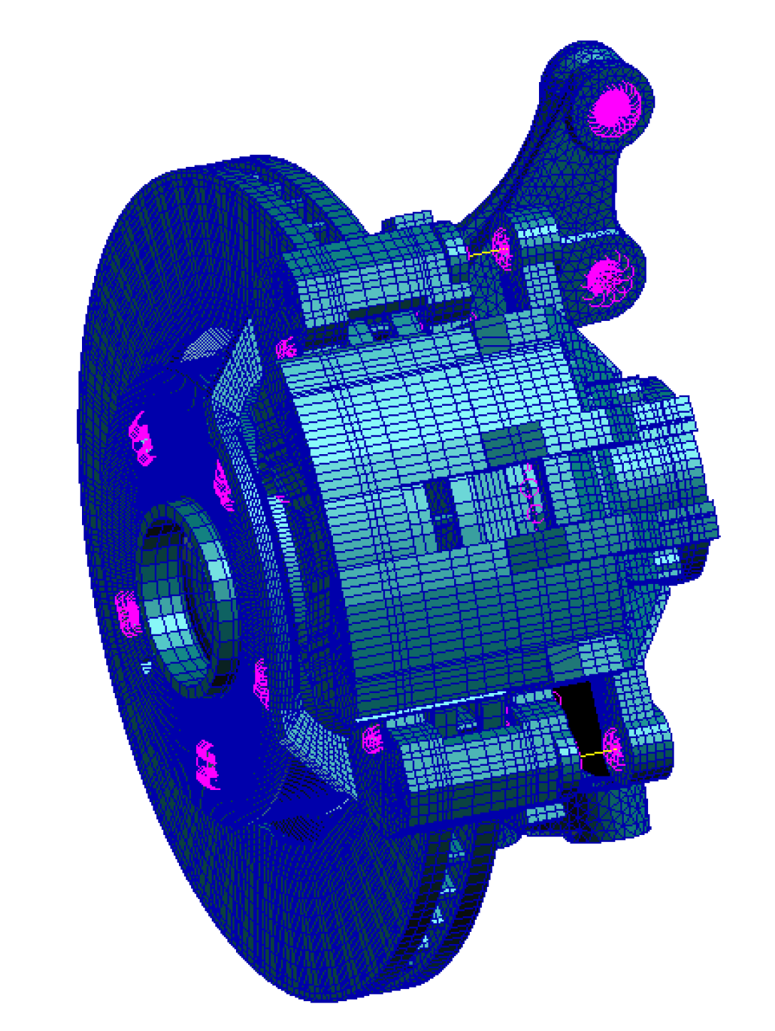
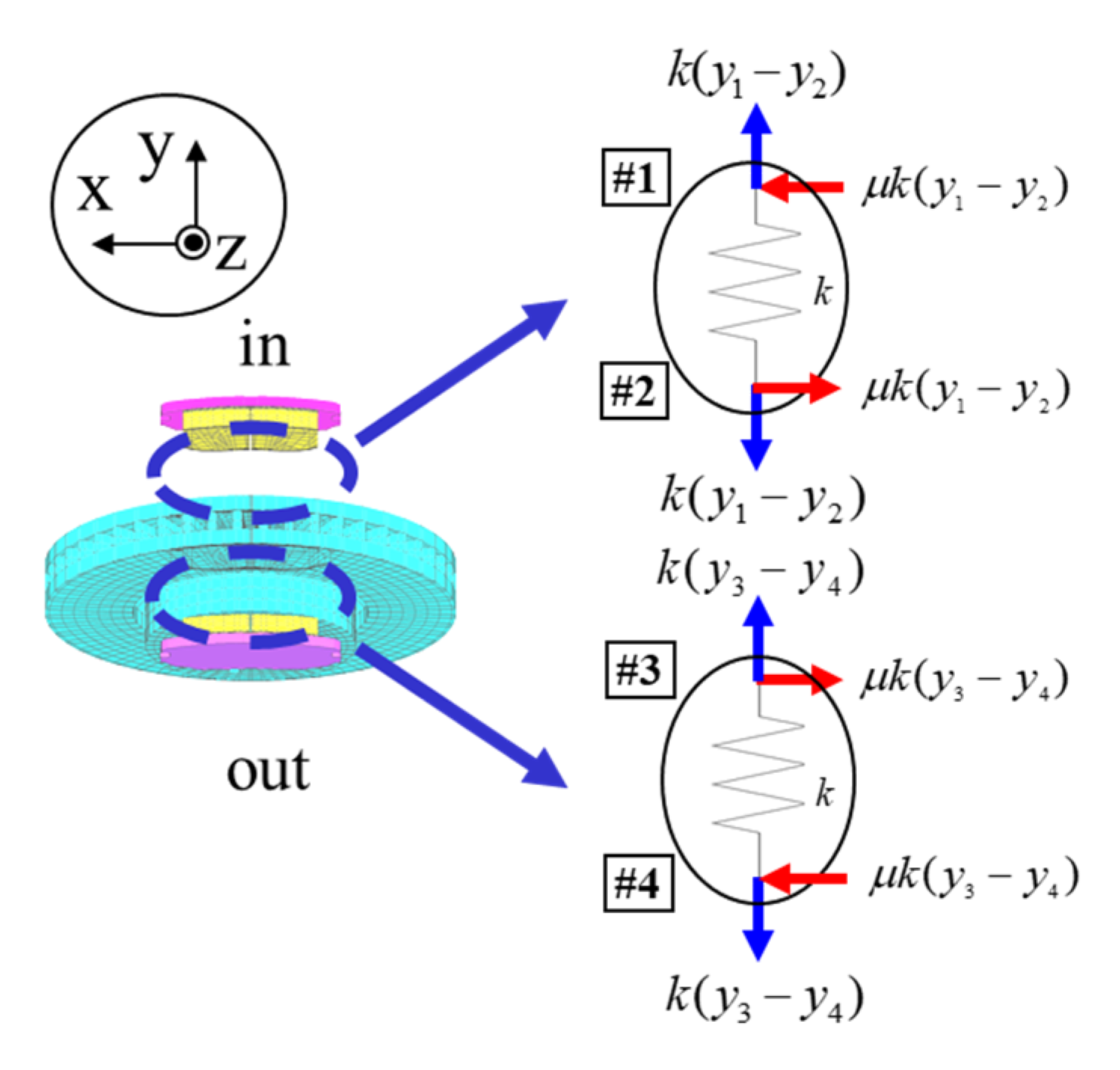
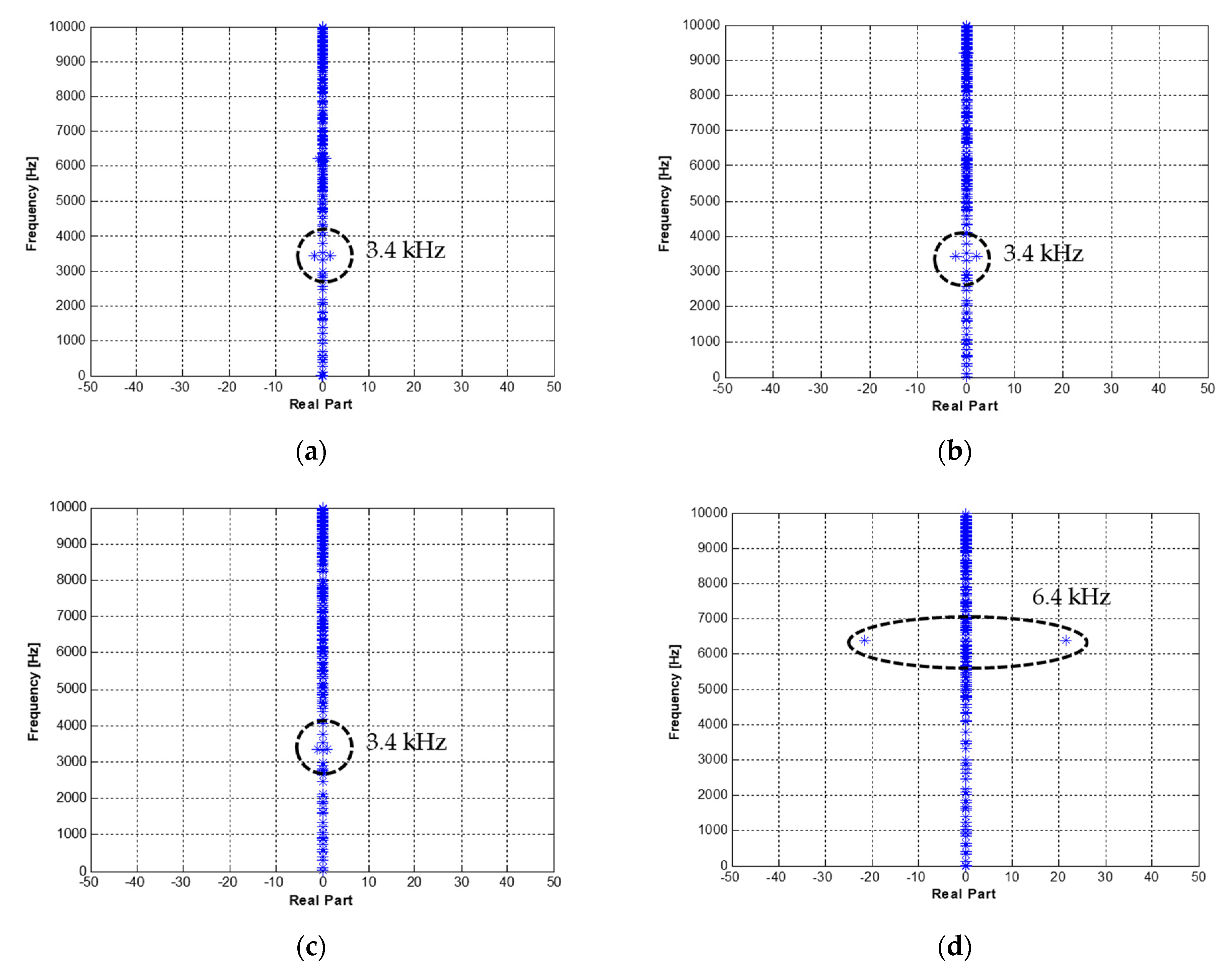
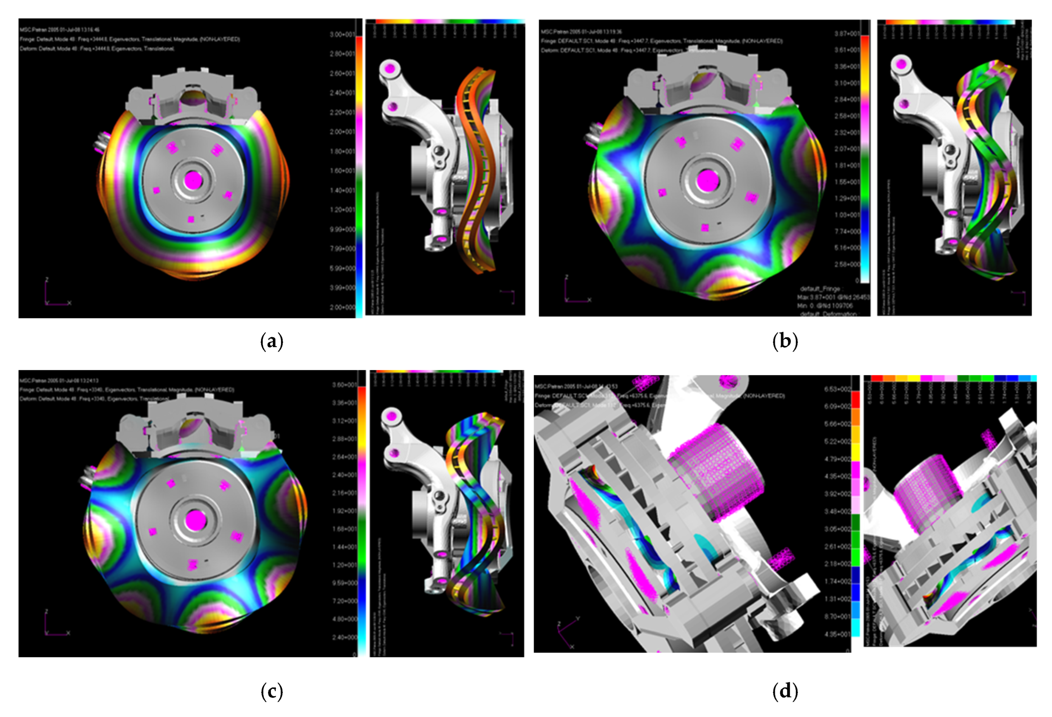
2. Stability Analysis of Assembled Brake System Model
3. Contribution Analysis of Assembled Brake System
3.1. Measurement of Squealing Frequencies
3.2. Forced Response Analysis of Assembled Brake System
3.3. Contribution Analysis of Assembled Brake System for Squealing
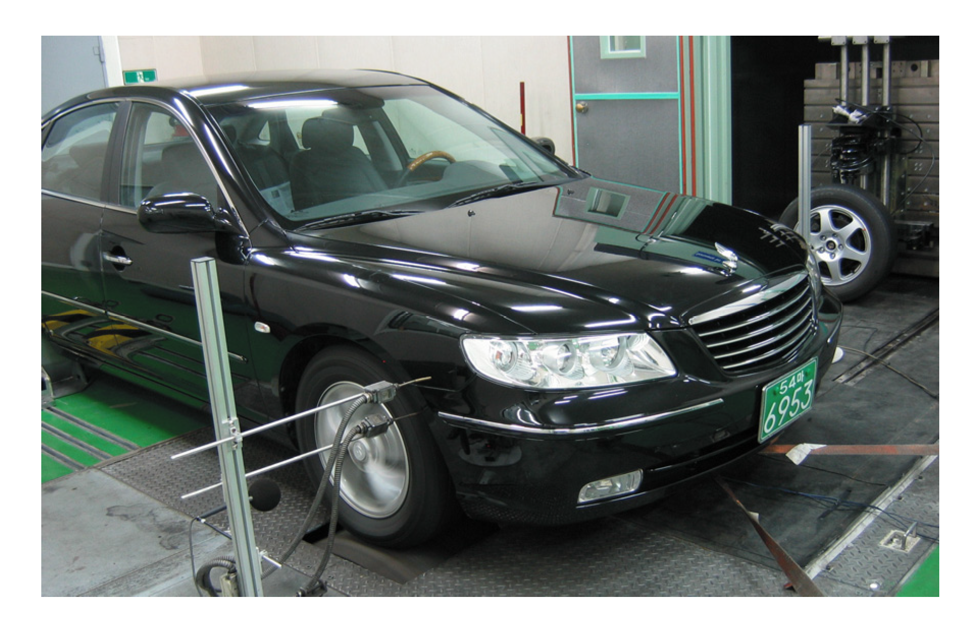
4. Validation from Vehicle Test
5. Conclusions
Author Contributions
Funding
Institutional Review Board Statement
Informed Consent Statement
Data Availability Statement
Conflicts of Interest
References
- Dunlap, K.B.; Riehle, M.A.; Longhouse, R.E. An investigation overview of automotive disk brake noise. J. Passeng. Cars 1999, 108, 515–522. [Google Scholar]
- Chung, C.H.; Steed, W.; Kobayashi, K.; Nakata, H. A new analysis method for brake squeal Part I: Theory for modal domain formulation and stability analysis. J. Passeng. Car Mech. Syst. J. 2001, 110, 2033–2039. [Google Scholar]
- Chen, F.; Tan, C.A.; Quaglia, R.L. Disk Brake Squeal–Mechanism, Analysis, Evaluation, and Reduction/Prevention; SAE International: Warrendale, PA, USA, 2005; pp. 1–26. [Google Scholar]
- Papinniemi, A.; Lai, J.C.S.; Zhao, J.; Loader, L. Brake squeal: A literature review. Appl. Acoust. 2002, 63, 391–400. [Google Scholar] [CrossRef]
- Kung, S.W.; Dunlap, K.B.; Ballinger, R.S. Complex eigenvalue analysis for reducing low frequency brake squeal. J. Passeng. Cars Mech. Syst. J. 2000, 109, 559–565. [Google Scholar]
- Park, J.P.; Choi, Y.S. Experimental analysis on brake squeal noise due to disk misalignment. Trans. Korean Soc. Automot. Eng. 2004, 12, 118–124. [Google Scholar]
- Kim, S.S.; Park, K.H.; Park, K.S. Complex eigenvalue analysis for reducing brake squeal. Spring Conf. Proc. Korean Soc. Automot. Eng. 2006, 959–964. [Google Scholar]
- Park, C.K.; Han, M.G.; Cho, S.S.; Choi, H.G.; Jeong, J.D.; Lee, J.M. A Study on the reduction of disk brake squeal using complex eigenvalue analysis. J. Passeng. Car Mech. Syst. J. 2001, 110, 2459–2463. [Google Scholar]
- Mahajan, S.K.; Hu, Y.K.; Zhang, K. Vehicle disk brake squeal simulations and experiences. J. Passeng. Cars 1999, 108, 2756–2762. [Google Scholar]
- Liles, G.D. Analysis of disk brake squeal using FE methods. J. Passeng. Cars 1989, 98, 1138–1146. [Google Scholar]
- Kwon, S.J.; Kim, C.J.; Lee, D.W.; Lee, B.H.; Na, B.C.; Kim, H.C. A study on the analysis of squeal noise for brake design. Trans. Korean Soc. Noise Vib. Eng. 2006, 16, 830–839. [Google Scholar]
- Kwon, S.J.; Kim, M.S.; Lee, B.H.; Lee, D.W.; Bae, C.Y.; Kim, C.J. The DOE based robust design to reduce the brake squeal noise. Trans. Korean Soc. Automot. Eng. 2007, 15, 126–134. [Google Scholar]
- Chung, C.H.J.; Steed, W.; Dong, J.; Kim, B.S.; Ryu, G.S. Virtual design of brake squeal. In Proceedings of the SAE 2003 Noise & Vibration Conference and Exhibition, Grand Rapids, MI, USA, 20–23 May 2003. [Google Scholar]
- Zhang, L.; Wang, A.; Mayer, M.; Blaschke, P. Component Contribution and Eigenvalue Sensitivity Analysis for Brake Squeal. In Proceedings of the 21st Annual Brake Colloquium & Exhibition, Hollywood, FL, USA, 6–8 October 2003. [Google Scholar]
- Kung, S.W.; Saligrama, V.C.; Riehle, M.A. Modal participation analysis for identifying brake squeal mechanism. In Proceedings of the 18th Annual Brake Colloquium and Engineering Display, San Diego, CA, USA, 1–4 October 2000. [Google Scholar]
- Kim, C.J.; Lee, B.H.; Lee, C.Y.; Jeong, H.I. Analysis of the induced brake moan noise in the coupled torsional beam axle suspension module. In Proceedings of the 23rd Annual Brake Colloquium and Exhibition, Orlando, FL, USA, 9–12 October 2005. [Google Scholar]
- Kim, C.J.; Kang, Y.J.; Lee, B.H.; Ahn, H.-J. Sensitivity analysis for reducing critical responses at the axle shaft of a lightweight vehicle. Int. J. Automot. Technol. 2012, 13, 451–458. [Google Scholar] [CrossRef]
- Úradníček, J.; Musil, M.; Gašparovič, L.; Bachratý, M. Influence of Material-Dependent Damping on Brake Squeal in a Specific Disc Brake System. Appl. Sci. 2021, 11, 2625. [Google Scholar] [CrossRef]
- Lai, V.-V.; Paszkiewicz, I.; Brunel, J.-F.; Dufrénoy, P. Multi-Scale Contact Localization and Dynamic Instability Related to Brake Squeal. Lubricants 2020, 8, 43. [Google Scholar] [CrossRef] [Green Version]
- Corradi, G.; Sinou, J.-J.; Besset, S. Prediction of Squeal Noise Based on Multiresolution Signal Decomposition and Wavelet Representation—Application to FEM Brake Systems Subjected to Friction-Induced Vibration. Appl. Sci. 2020, 10, 7418. [Google Scholar] [CrossRef]
- Joerger, A.; Spiropoulos, I.; Dannecker, R.; Albers, A. Multi Scale Modelling of Friction Induced Vibrations at the Example of a Disc Brake System. Appl. Mech. 2021, 2, 1037–1056. [Google Scholar] [CrossRef]
- Joe, Y.G.; Cha, B.G.; Sim, H.J.; Lee, H.J.; Oh, J.H. Analysis of Disk Instability Due to Friction-induced Vibration Using a Distributed Parameter model. Int. J. Automot. Technol. 2008, 9, 161–171. [Google Scholar] [CrossRef]
- Oura, Y.; Kurita, Y.; Matsumura, Y.; Nishizawa, Y. Influence of Distributed Stiffness in Contact Surface on Disk Brake Squeal. In Proceedings of the SAE 26th Brake Colloquium & Exhibition, Tochigi, Japan, 13 October 2008. [Google Scholar]
- Dihua, G.; Dongying, J. A Study on Disc Brake Squeal Using Finite Element Methods. Appl. Acoust. 1998, 69, 147–162. [Google Scholar]
- Kim, C.; Kwon, Y.; Kim, D. Analysis of low-frequency squealing in automotive disc brake by optimizing groove and caliper shapes. Int. J. Precis. Eng. Manuf. 2018, 19, 505–512. [Google Scholar] [CrossRef]


| Part | Poisson’s Ratio | ||
|---|---|---|---|
| disk | 125 | 0.3 | 7200 |
| brake pad | 0.35 | 0.2 | 1450 |
| backplate | 210 | 0.3 | 7800 |
| caliper | 175 | 0.3 | 7760 |
| housing | 175 | 0.3 | 7760 |
| hub | 210 | 0.3 | 7800 |
| piston | 210 | 0.3 | 7800 |
| knuckle | 210 | 0.3 | 7800 |
| Pad Shape | Squealing | Sound Pressure Level | |
|---|---|---|---|
| Base brake pad ) | 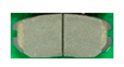 | Yes | 74–78 dB(A) |
| ) |  | No | - |
Publisher’s Note: MDPI stays neutral with regard to jurisdictional claims in published maps and institutional affiliations. |
© 2022 by the authors. Licensee MDPI, Basel, Switzerland. This article is an open access article distributed under the terms and conditions of the Creative Commons Attribution (CC BY) license (https://creativecommons.org/licenses/by/4.0/).
Share and Cite
Kwon, S.-J.; Kim, C.-J. Contribution Analysis of Assembled Brake System to Reduce Squealing. Appl. Sci. 2022, 12, 11232. https://doi.org/10.3390/app122111232
Kwon S-J, Kim C-J. Contribution Analysis of Assembled Brake System to Reduce Squealing. Applied Sciences. 2022; 12(21):11232. https://doi.org/10.3390/app122111232
Chicago/Turabian StyleKwon, Seong-Jin, and Chan-Jung Kim. 2022. "Contribution Analysis of Assembled Brake System to Reduce Squealing" Applied Sciences 12, no. 21: 11232. https://doi.org/10.3390/app122111232