1. Introduction
Cooperative Intelligent Transport Systems (C-ITS), centered on real-time traffic, seek to overcome the drawbacks of existing Intelligent Transport Systems, which mainly focus on traffic management [
1,
2,
3]. Despite various sensors installed in a car, only limited environmental information is obtained when driving over high hills or in foggy weather. Vehicle-to-Everything or Vehicle-to-X (V2X) is a communication technology that allows you to collect and share real-time traffic information, both visible and invisible, with other vehicles, road infrastructure devices, networks, and pedestrians [
4].
The Cellular version of V2X (C-V2X) combines Wireless Access for Vehicle Environment (WAVE) and communication technology, both designed to operate in the dedicated frequency band (5.85 to 5.925 GHz) for V2X applications [
5].
Irrespective of using either WAVE or C-V2X, the communication environment must be seamless and reliable. It must efficiently relay information regarding road safety-related situations, such as lane changes, warnings, and collision detection. The antenna is a crucial component of the V2X system, which provides a reliable connection between the vehicle and other networks.
In actual road conditions, vehicle locations vary depending on the distance and their driving lanes. Therefore, for stable Vehicle-to-Vehicle (V2V) and Vehicle-to-Infrastructure (V2I) communication, the radiation pattern of the antenna must be 360° (omnidirectional) and horizontally oriented [
6]. Generally, an increase in antenna gain enables long-distance communication, but in this case, the bandwidth must be reduced. However, if a null point occurs in a specific direction, communication gets disconnected in that direction. Therefore, to achieve stable communication without interruption in any situation, the antenna gain of 360 degrees must be at or above a certain value, with omnidirectional radiation beam patterns. That is, a new antenna structure is required to minimize the null points with sufficient gain.
Stable communication is possible while driving only when the antenna radiation pattern forms at 90° in the horizontal direction for both front and rear vehicle communication, 85° for a vehicle on a hill, and 80° for a base station at a height of 6 m, respectively [
7]. Although the shape of the actual theoretical radiation pattern is omnidirectional, it is difficult to implement this for an antenna attached to the top of a metal vehicle, due to the wide reflector, a nearby GPS antenna, and another antenna, which results in a null area.
In [
8], for a bidirectional patch antenna, a gain of 6.62 dBi was obtained using three patches, but a null region of −10 dBi or less occurred due to the flat conformal structure. In [
9], despite implementing omnidirectionality, it was difficult to install two antennas inside the shark-fin module due to its large size. In [
10,
11], for the monopole structure, a significant null region occurs due to the finite ground size. In [
12,
13], two compact V2X antenna solutions were proposed, but due to the characteristics of the collinear array antenna structure, the height was approximately 50–60 mm. In order to simultaneously implement the frequency modulation (FM), amplitude modulation (AM), and WAVE antennas in the shark-fin module, the height of the WAVE antenna must be lowered.
In this study, we propose an antenna structure with omnidirectional characteristics while lowering the height of the collinear array antenna in the finite ground of the shark-fin module by adding closed-loop devices to the monopole. In particular, the gain can be improved by focusing the flow of the surface current of the ground around the antenna through closed-loop devices.
In this study, we investigated the influence of closed-loop devices on beam patterns radiated from existing monopole WAVE antennas. The effects were analyzed by introducing single, dual, and quadruple closed-loop devices into an existing monopole antenna. Furthermore, the surface current, radiated beam patterns, and average gain were analyzed by using the high-frequency structure simulator (HFSS) and computer simulation technology (CST) programs. The effects on the beam patterns radiated from a monopole antenna, based on the number of closed-loop devices, i.e., one, two, and four, were also analyzed. The designed monopole WAVE antennas with closed-loop devices were implemented and their characteristics were compared with the simulation results.
2. Materials and Methods
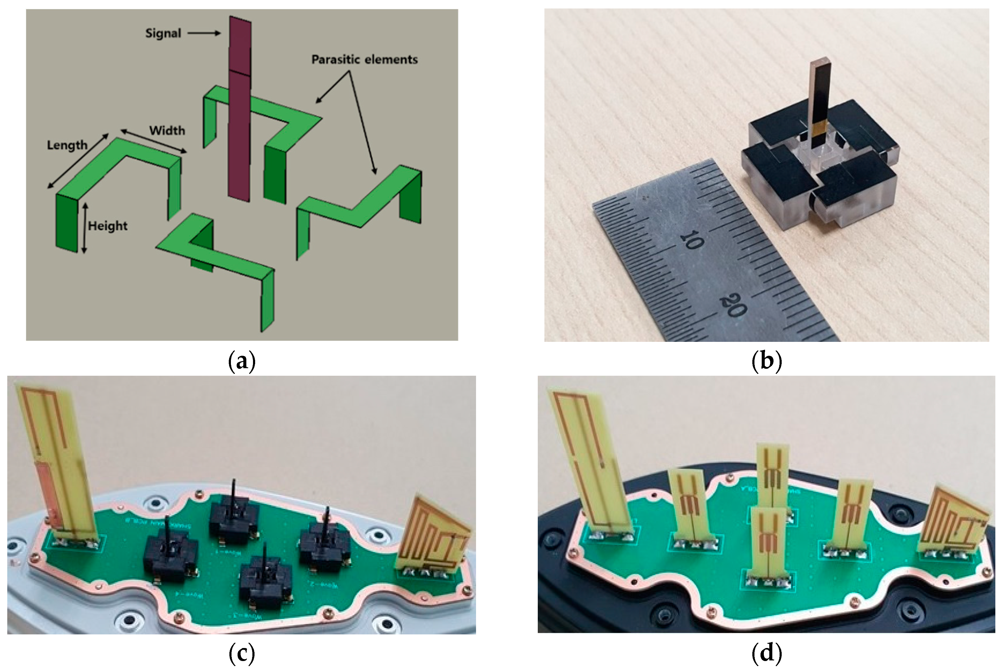
Figure 1 shows the schematic and photo image of the designed WAVE antenna with closed-loop devices. In a current WAVE antenna without a closed-loop device, the height of the antenna should be greater than 50 mm because of weak radiated beam patterns [
12,
13]. Contrastingly, by introducing a closed-loop device, the height of the WAVE antenna can be lowered to 9.97 mm. As the distribution of the surface current flowing to the ground is widened by introducing closed-loop devices to the ground, the disadvantage of the finite ground of the monopole antenna can be compensated. Additionally, it is effective in obtaining omnidirectional characteristics because they also act as a reflector for the radiated beams from the monopole antenna. Moreover, null points, where the minimum gain is below −20 dBi in a monopole-only WAVE antenna, can be alleviated by introducing closed-loop devices.
The width, length, and height of closed-loop devices were designed to be of 3.04, 5.00, and 2.90 mm, respectively, as shown in
Figure 1a,b. The dimensions of the closed-loop devices were determined by considering the resonance and omnidirectional beam patterns in the operating frequency range of 5.850 to 5.925 GHz, used in the WAVE antenna. The height of the monopole antenna was designed to be about 9.97 mm (approximately 0.24 λ), and the total length of each closed loop device was determined to be 13.84 mm (approximately 0.34 λ). To form a resonance between 5.85 and 5.925 GHz of the WAVE antenna’s operational frequency and implement an omnidirectional beam pattern, the distance between the signal and closed-loop devices must be larger than 0.24 λ. This is slightly smaller compared to previous reports, where the distance between the signal and the parasitic elements ranges from 0.3 to 0.4 λ [
14,
15]. The proposed antenna was realized on the FR4 with a substrate (ε
r = 4.3,
= 0.025) of 0.8 mm thickness and signal and closed loop devices of 0.1 mm metal thickness.
Figure 1c shows a photo image of the fabricated quadruple closed-loop devices introduced to the monopole WAVE antenna. The fabricated antenna was mounted on a shark-fin module for evaluation in the real environment. It comprised two LTE antennas and four designed antennas.
Figure 1d shows a conventionally used monopole-only antenna without a closed-loop device, which was fabricated for comparison with the designed antenna.
3. Results
Figure 2 shows the surface current distribution when there are one, two, and four closed-loop devices with a general monopole antenna. The surface current is wider in the direction where there is a closed-loop, as illustrated in
Figure 2. Therefore, it can be expected that the beam pattern will become stronger in the opposite direction of the closed-loop devices. As the number of closed-loop devices increases, the surface current gets centered around the monopole antenna, and its density also increases.
Figure 3 shows the surface current and magnetic field characteristics of a closed-loop device. Because of the role of closed-loop devices as a reflector of the beams emitted from the monopole, the density of the magnetic field is high around the monopole, and there is a slight fluctuation according to the difference in gain value. The magnetic field distribution shown in
Figure 3b is strongly distributed around the monopole and the closed-loop device, and the distribution is stronger around the monopole. If the dimension of the closed-loop device is adjusted, the strength of the magnetic field in a specific direction can be strengthened, thereby enabling smoother communication in that direction. This is one way to increase the gain value of the beam pattern between 80° and 90° in a specific direction for facilitating smooth communication between vehicles on the road, vehicles traveling on hills, and base stations.
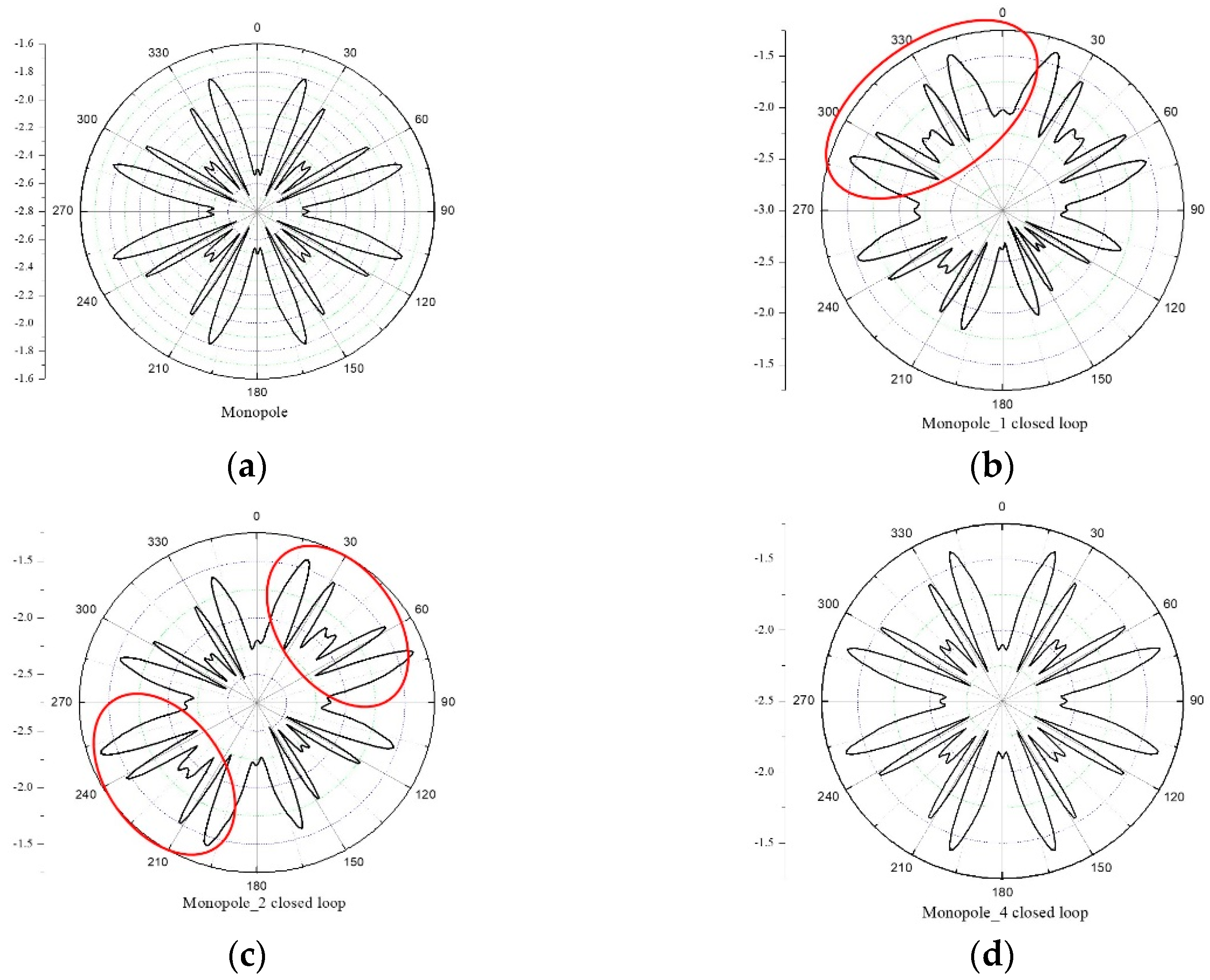
The beam patterns radiated from the monopole WAVE antenna on the 400 mm ground were analyzed by changing the number of closed-loop devices. As in the surface current distribution characteristics shown in
Figure 2, the effects of the number of closed-loop devices on the radiated beam patterns from the monopole WAVE antenna appear similar. Even when there is only a monopole antenna without closed-loop devices, omnidirectional radiation characteristics are exhibited to some extent. However, for a specific angle, a decrease in gain value can be seen, as presented in
Figure 4a.
As shown in
Figure 4b, when one closed-loop device is installed, the gain value of the beam pattern increases in the opposite direction, and is denoted as a red circle. That is, when the closed-loop device is installed at around 120° to 150°, the density of the beam pattern increases in the area between 270° and 360°. It was verified that the role of the closed-loop device is to reflect the signal radiated from the monopole antenna in the opposite direction of its installed location.
Figure 4c shows the results of the beam pattern analysis when two closed-loop devices were installed in a diagonal direction. Similar to
Figure 4b, a closed-loop device was additionally installed between 30° and 60° and another between 210° and 240°. The gain value of the beam pattern increased in the opposite direction (marked by red circles) in the results shown in
Figure 4c. Compared to the result shown in
Figure 4b, which is of a single installed closed-loop device, the density of the beam pattern increased even in the region between 120° and 150°, indicating that the two closed-loop devices worked independently. Moreover, it was verified once again that the role of the closed-loop device is to reflect the signals emitted from the monopole.
For the final step, four closed-loop devices were installed on the monopole WAVE antenna to obtain omnidirectional radiation beam patterns with an enhanced gain value. Quadruple closed-loop devices were installed for a 360° coverage. Compared to instances where one and two closed-loop devices were installed, the gain value of the beam pattern increased evenly over the entire 360° direction, as shown in
Figure 4d (see the different scale in
Figure 4). If there was interference between the closed-loop devices and the beam pattern, the gain value of the signal radiated from the monopole would not have increased evenly. This proved that quadruple closed-loop devices work independently without affecting each other.
Uniformly increasing the overall gain by reducing the loss results in the signal radiated from the monopole antenna being reflected through the closed-loop device and radiated to the outside. The currently used monopole antenna without a closed-loop device is at a disadvantage, wherein the height of the monopole must be relatively high to minimize the loss of the radiated signal [
13,
14]. However, when the closed-loop device is mounted on the monopole antenna, the height can be reduced because the closed-loop device can minimize the density of the signal radiated from the monopole by reflecting the signal in the opposite direction. Therefore, despite reducing the height of the existing monopole antenna from 50 to 60 mm to 9.97 mm, the average gain value was able to maintain the omnidirectional beam pattern characteristics while sustaining the increased gain. It can be concluded that the role of the closed-loop device is to increase the intensity of the beam, i.e., the gain value, by reflecting the beams radiated from the monopole antenna back around the monopole, as shown in
Figure 4.
The radiation pattern of the signal at a specific angle is also very important for facilitating the smooth inter-vehicle communication of autonomous vehicles and communication with the base station. The radiation pattern of the antenna is important at 90° for communication between vehicles, at 80° for communication with base stations located 6 m high, and at 85° when driving on a hill [
7]. At these angles, it should have an omnidirectional radiation pattern and a gain value large enough for stable communications.
Figure 5 shows the two-dimensional (2D) and three-dimensional (3D) radiation beam patterns of the WAVE antenna installed only with a monopole antenna and no closed-loop device on the shark-fin module (in
Figure 1d). The characteristics of the radiation pattern were analyzed to verify whether smooth communication was achieved at angles of 80°, 85°, and 90°, respectively; a 3D view is presented in
Figure 5d.
Conversely, the 2D- and 3D-radiated beam patterns from the monopole WAVE antenna with quadruple closed-loop devices on the shark-fin module (in
Figure 1c) are shown in
Figure 6. The 2D null value comparison of monopole-only (red color) and monopole with quadruple closed-loop devices (green color) at angles of 80°, 85°, and 90°, respectively, is shown in
Figure 7a–c. At 80°, the null value is enhanced from −30.8 to −4.7 dBi. At 85°, the null value is enhanced from −26 to −5.5 dBi, and at 90°, the null value is enhanced from −21 to −6 dBi. From these simulation results, the monopole-only antenna has a serious null point when installed on the shark-fin module. However, the proposed antenna, a monopole with a closed-loop device, has an omnidirectional beam pattern without a null point.
Figure 8 shows the surface current of the antennas when installed on the shark-fin module. For the monopole-only antenna (in
Figure 8b), it can be seen that the surface current affects surrounding antennas through the ground. However, for the proposed antenna (in
Figure 8a), the surface current is concentrated only around the antenna. This proves that the four devices form a closed-loop path for the surface current. By allowing the surface current to focus only around the antenna, the characteristics of the gain and beam pattern of the antenna can be improved. These characteristics improve isolation performance in the shark-fin module, which requires multiple antennas to be installed on the common ground.
We also implemented monopole WAVE antennas with four closed-loop devices and characterized their properties to assess their practical applicability. The implemented monopole WAVE antenna was mounted on a shark-fin antenna (
Figure 1c,d).
Figure 9 shows the result of analyzing the beam pattern for smooth communication at 80°, i.e., the communication between a vehicle on the road and a base station installed at a height of 6 m.
The simulation results of the case where there was only a monopole antenna and when quadruple closed-loop devices were installed in the monopole antenna on the shark-fin module were compared with the experimental results. When only the monopole was installed (
Figure 1d), it was confirmed that there was a null point, indicating a very low gain value at 24°. However, when quadruple closed-loop devices are installed in the monopole antenna (
Figure 1c), the gain value increases to 24°, and the null point shown in the simulation result disappears. The gain values at this angle were −31 and −4.9 dBi, respectively. The measured results obtained by mounting on the actual shark-fin antenna are shown in blue. The gain value at the same angle is 0.74 dBi, which is a 32.74 and 7.64% increase compared to the simulation result, respectively. The average gains of the WAVE antenna were also compared in addition to the gains at the null point. The average gain of the monopole-only WAVE antenna was −2.94 dBi, which was obtained via HFSS simulation. Conversely, the average gain obtained from the WAVE antenna with closed-loop devices was −0.3 dBi, which was further increased. Furthermore, the average gain obtained from the measurement of the WAVE antenna with closed-loop devices was 1.57 dBi. Therefore, the average gain increased in the fabricated monopole antenna with quadruple closed-loop devices. It can be concluded that the role of closed-loop devices in reflecting the radiated signals from the monopole antenna coincided with the results of
Figure 4.
Figure 10 shows the return loss of the monopole antenna with quadruple closed-loop devices. The simulated and measured return losses within the operating frequency were below −14 and −17 dB, respectively.


