Abstract
This paper aims to provide a novel control framework for exactly regulating the output voltage of floating interleaved boost converters (FIBCs), which have been widely employed in fuel cell applications in recent years. Firstly, a mathematical model of the FIBC is constructed according to Kirchhoff’s current and voltage loop principles. Then a cascade control structure with a current inner loop and voltage outer loop is developed to achieve the desired voltage regulation performance. The current controller is established based on the generalized super-twisting algorithm (GSTA) to ensure that the inductor current exactly follows the current reference, which is generated by the outer loop. Meanwhile, an active disturbance rejection control (ADRC) framework is utilized for robustly regulating the output voltage despite the presence of input variation and load change in the voltage control loop based on a nonlinear continuous GSTA-based extended state observer (GSTA-based ESO). The stability of a closed loop system based on the GSTA controller and the GSTA-based ESO is conclusively proven using the Lyapunov theory. The Simscape model of the FIBC is developed, which is used to verify the feasibility and the appropriateness of the recommended control algorithm. Finally, numerical simulations are carried out to demonstrate the effectiveness of the proposed method compared to several previous works.
1. Introduction
The issue of environmental pollution has been receiving great attention from governments and people around the world in recent decades [1,2]. One of the culprits for this problem comes from the carbon dioxide emission of vehicles that use fossil fuels, such as gasoline or diesel, to generate energy [3]. Meanwhile, the shortage of fossil fuels leads to the requirement of employing alternative sustainable energy resources, such as fuel cells (FCs), solar energy, wind energy, and so on, in industrial applications instead of using the above traditional fuels. Among them, solar and wind energy resources have some disadvantages of severe weather dependence, expensive storage systems, and large installation space, as well as being associated with pollution. Hence, although the cost of hydrogen production is now relatively high, fuel cell energy still is considered a potential power source for future power systems due to its high power production and zero-emissions, as well as the qualities of reliability, high efficiency, and compactness [4,5]. However, some disadvantages of the fuel cell systems such as low-and-unregulated output voltage and excessive ripples of output current [6] restrain their applicability in real-life applications.
In order to amplify the output voltage of FC energy systems and maintain a constant DC bus voltage at a high-level stable voltage, DC–DC boost converters or step-up converters [7,8,9] are generally adopted as an interface between the low-voltage side (FC) and high-voltage side (DC bus). Conventional DC–DC boost converters have the benefits of low-cost and simple structure; however, their voltage gains are relatively small due to the parasitic resistance on the inductors and capacitors [10]. Hence, numerous enhanced topologies of DC–DC step-up converters [4,6,11,12,13,14,15,16] have been innovated and they are demonstrated to be more appropriate for fuel cell applications than the conventional boost converter. As an illustration of them, interleaved boost converters (IBCs) [13,17,18,19,20] can be considered a remarkable selection with their high amplifying coefficient and low voltage stress for power switches. In addition, by virtue of interleaved structure, IBCs are tolerant towards a low input current ripple, and consequently, they are suitable for a wide range of FC-based applications. However, how to achieve a desired voltage regulation qualification for such IBCs in the presence of input variation and load change is still a challenging task that has attracted considerable attention from the research community recently.
It should be noted that the proportional–integral–derivative (PID) controllers and their modifications are still valuable solutions for regulating the output voltage of step-up DC–DC converters, which were broadly employed in previous works [21,22,23,24,25]. For instance, Zhidong Qi et al. [21] developed a combination between a new switch strategy and a fractional order PID controller for a four-switch buck-boost converter, whose controller gains were optimized using a partial swarm optimization (PSO) algorithm, and consequently, a better performance was achieved compared to the conventional integer order controller. In addition, in [22], S. K. Kim and C. K. Ahn constructed a voltage regulation loop in which a disturbance observer-based proportional–derivative (DOB-based PD) controller for DC–DC boost converters was established to maintain a constant output voltage and cope with the parameter and load variations, simultaneously. In addition, a robust PID controller using the equivalent feedforward of the modified direct synthesis (MDS) approach, which incorporates the dynamic disturbance model in the controller design phase [23] for DC–DC boost converters, was constructed. To increase the voltage regulation performance and the robustness of the closed-loop system, various robust nonlinear control techniques have been adopted. In [26,27], a model reference-based control with time delay estimation (TDE) was introduced to compensate for unknown terms that are lumped into generalized disturbance and, consequently, guaranteed that the behavior of the system follows the output of the reference model. Nevertheless, the first-order derivative of the inductor current, which is difficult to accurately compute, was required. Furthermore, some nonlinear control techniques [28,29,30] have been adopted for DC–DC boost converters to increase the robustness of the voltage regulation. It should be noted that the above single loop structures possess cost-effectiveness, simplicity, and simple implementation; however, such regulation mechanisms cannot achieve the desired control performance.
By virtue of exact voltage regulation for DC–DC step-up converters, the cascade control structure has been broadly adopted in numerous studies [31,32,33,34] recently. For example, in [32], a linearized small-signal model around the operating point of a general N-phase interleaved boost converter was introduced, and a cascade control scheme with PID controllers using nominal parameters was subsequently established. The results showed that the proposed control approach was robust against parameter variations, and high conversion efficiency was also attained. Nevertheless, the performance of the closed-loop system varies with the distinct operation points. To overcome this drawback, a dual-loop control algorithm based on flatness control theory and active disturbance rejection control (ADRC) for two-phase interleaved boost converters (TIBCs) was introduced in [33,34] where linear extended state observers (LESOs) were employed to estimate the uncertain input voltage and output current, and consequently, the output voltage was maintained at the desired level. In addition, disturbance observer-based control approaches [35,36] were also investigated for stabilizing the output voltage of traditional DC–DC boost converters. Moreover, the integration of proportional-integral (PI) controllers used for the current loop and the ADRC for the outer loop has been a popular technique, which was employed in several existing works [19,37] in robustly stabilizing the output voltage of floating IBCs (FIBCs) in recent years. In [13], X. Hao et al. introduced a dual loop control scheme for a four-phase IBC, which has a backstepping-based current control law and STA-based voltage controller in the outer loop under the different working conditions in the presence of the deviations of circuit components. The control parameters were subsequently optimized by using the PSO algorithm. Furthermore, to increase the convergence rate of the inner current loop, the super-twisting algorithm (STA)-based controller was employed along with the ADRC developed for the outer voltage loop [17,38]. However, it should be noted that the employment of the general super-twisting algorithm (GSTA) in developing the current controller and an ESO-based ADRC for regulating the output voltage of FIBCs has not been investigated in the literature.
Motivated by the above analysis, in this paper, a nonlinear continuous ESO based on GSTA is introduced to cope with the lumped uncertainties in the system dynamics of the considered FIBC. In addition, the current controller is realized based on the GSTA, which ensures the inductor current follows the current reference in finite time. Thanks to that, a new ESO-based control approach is developed to increase the robustness of the closed-loop control system in the presence of a wide range of input variations and load changes, which have not been reported in the literature. The main contributions of this research work are summarized as follows:
- The finite-time boundedness stability of the GSTA-based controller for uncertain nonlinear first-order systems and GSTA-based ESO is rigorously proven by employing the Lyapunov theory.
- For the first time, the GSTA is employed to establish the inner current loop, which guarantees a faster convergence rate and a higher control accuracy of the inductor current in contrast to the conventional STA-based and PI current controllers.
- Compared to the conventional ESO [39] and high-order ESO [38], an improved estimation performance of lumped time-varying disturbance is achieved by the nonlinear continuous GSTA-based ESO introduced in this paper. Hence, a better voltage regulation capability is attained by the proposed approach with the same cascade architecture as the control algorithms developed in [38,39] in the presence of both input variation and load change.
The rest of the paper is organized as follows. Section 2 introduces the controller and observer design procedure by using the GSTA theory. The mathematical representation of multi-phase interleaved boost converters is presented in Section 3. Section 4 develops the cascade control scheme with the GSTA-based current controller and nonlinear continuous ESO-based controller for the studied FIBC. Then the advantage of the proposed method is verified in Section 5 through several numerical simulations. Finally, Section 6 concludes the paper.
2. Generalized Super-Twisting Algorithm-Based Controller and Observer Design
2.1. Finite-Time Stability
Lemma 1
([40]). Let be a continuous positive definite differential function if there exist some scalars , , , and such that
The function converges to a region that is bounded by
where is a scalar, and the settling time is given by.
2.2. Generalized Super-Twisting Algorithm Controller Design
Consider the following first-order single-input single-output (SISO) nonlinear system
where denotes the sliding variable, represents an unknown perturbation that is bounded by with as an unknown positive constant, b is the control gain, and u is the control input.
The generalized STA (GSTA) [41] is a modified version of the conventional STA by simply adding some extra correction terms, which was originally introduced by J. A. Moreno. Since the added linear terms are stronger than the nonlinear ones when the system trajectories are far from the origin, the robustness and the convergence speed of the closed-loop system are improved accordingly. The GSTA-based controller of the system (4) is given by
where and are positive constants to be designed, and the two functions and are given by
where , , and is the standard signum function, which is given by
Based on the definition of the functions and in (6), we have
where denotes the partial derivative with respect to .
According to the control laws (5) and the system dynamics (4), the closed-loop system dynamics become
Lemma 2.
Proof of Lemma 2.
Define the augmented state vector as . Taking the time derivative, one obtains
where the matrices and are given by
Based on the definition of vector , an important property can be derived as
Since the matrix is Hurwitz, there exists a symmetric positive definite satisfying the following Lyapunov equation
where is a symmetric positive definite matrix.
Consider the following Lyapunov function
From (13), we have
Based on Lemma 1, the function given by (13) reaches a region whose bound is determined by , , , and in finite time. Hence, according to the definition of the vector , the sliding variable is restricted by an arbitrarily small value as a result.
This completes the Proof of Lemma 2. □
2.3. Nonlinear Continuous ESO Design
Consider the following system
where is the lumped disturbance term, u is the input of the system, denotes the known control gain, and x represents the system state that is measurable. It is assumed that the lumped disturbances are differential, and the first-order time derivative of it is bounded by an unknown constant, i.e., .
Defining as an extended system state, the system (18) can be transformed into the following augmented system
where is the first-order derivative of .
The nonlinear continuous ESO [42] based on GSTA is constructed to estimate the lumped disturbance term as follows:
where and are estimates of x and , respectively; is the correction term; and represent the observer gains; and the two functions and are given by
where and .
Lemma 3.
Proof of Lemma 3.
Define the new state vector . Based on this, we have
where the matrices and are given by
Since the matrix is negative definite, there exists a positive symmetric matrix satisfying the following Lyapunov equation
A candidate Lyapunov function is chosen as
Based on this, we have
Moreover, according to the definition of , one obtains
Taking the derivative of (25) yields
The observer gains and are chosen such that the two terms and are positive. According to this, the finite-time convergence of the estimation errors is achieved.
Based on Lemma 1 and (29), Lemma 3 is completely proven. □
3. System Modeling and Problem Formulation
The schematic of the studied FIBC is illustrated in Figure 1. are the power switches, are the diodes, are the inductors, are the capacitors, and R is the load resistor. For the sake of simplicity, it is assumed that the circuit parameters, i.e., inductance and capacitance, on the two branches of the FIBC are completely identical. Based on this assumption, we have
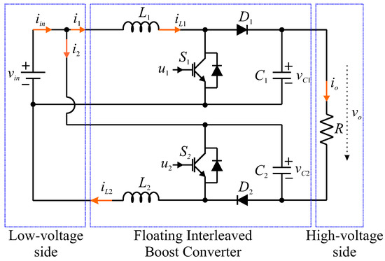
Figure 1.
The schematic of the considered DC–DC boost converter.
According to the Kirchhoff’s current and voltage laws, the average model of the FIBC in the continuous mode is given by
where is the input voltage, are the capacitor voltages, represents the currents through the inductors, denotes the load current of the FIBC with as the output voltage, and reflex the duty cycles of the PWM signals applied to the power switches.
The output voltage of the FIBC is determined as
Hence, the voltage gain in continuous conduction mode is computed through the following equation
where D is the equivalent duty ratio of the PWM pulse applied to the power switches.
Remark 1.
According to the voltage amplification coefficient Equation (33), it can be seen that the voltage gain of the FIBC is significantly higher than that of the conventional DC–DC boost converter. It indicates that the FIBC is one of the most appropriate solutions for fuel cell applications such as electric vehicles or DC microgrid applications, which require a stable few hundred volts of the DC bus while the input voltage is generally low.
The main control objective is to stabilize the output voltage of the FIBC at the desired level under the input variation and load change, which naturally exists in real-life fuel cell applications such as electric vehicles and DC microgrids. To continuously monitor the current through inductors and the output voltage of the FIBC, two current sensors and a voltage sensor are adopted, respectively. In the system dynamics (31), the input voltage and load change are considered the external disturbances, which degrade the system performance of the FIBC.
4. Control System Synthesis
The cascade structure for regulating the output voltage of the FIBC is illustrated in Figure 2. The inner current control loop ensures the inductor current exactly tracks the current reference that is generated by the outer voltage control loop in finite time despite the variation of input voltage. To control the ON–OFF state of the power switches, two PWM signals are constituted based on the control actions constructed by the inner loop. Meanwhile, the output voltage of the FIBC is guaranteed to closely follow the voltage reference in the presence of load change, which always exists in fuel cell applications.
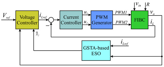
Figure 2.
The suggested control scheme for the FIBC.
4.1. Current Controller Design
Consider the following current dynamics of the FIBC
The sliding variables are defined by
where is the current reference and .
It can be seen from (34) and (35) that the sliding variables (35) have a relative degree, one with respect to the control input. Hence, the GSTA can be adopted to construct the current control law to ensure that the inductor current follows the reference in finite time in spite of the variation of the input voltage as
where and are controller gains, is the auxiliary control variable, and the two functions and are given by
where and are positive constants.
In the sliding mode, we have
Due to the symmetric property of the two branches of the FIBC, one obtains
Based on this and according to (34), the equivalent control input is given by
4.2. Active Disturbance Rejection Control for Voltage Loop
From (41), the equilibrium point is determined as
Hence, (42) can be rewritten in the following form
where is the fictitious control input and coefficients , , and are given by
Remark 2.
From (44), it can be recognized that the output voltage of the FIBC is disturbed by not only the variation in input voltage but also the load change. In addition, the control gain β is unknown since it depends on the unmeasurable input voltage. Therefore, an active disturbance rejection control framework should be employed to compensate for the adverse effects of the above disturbances and achieve a high voltage regulation performance.
To address the unknown control gain, the dynamic of the output voltage is transformed into
where is a positive constant in (46), which is determined based on nominal parameters of the FIBC and is the total disturbance term with w characterized as the input variation and load change effects.
Assumption 1.
The total disturbance is differential and the upper bounded of its first-order derivative is restricted by an unknown constant, i.e., .
Defining the state vector , (46) can be converted into
where .
A nonlinear continuous ESO is adopted as
where is the difference between the estimated value and measured value of the state , and are estimates of and , respectively, is the bandwidth of the observer, and
where and are positive constants.
Remark 3.
Considering the system dynamics (47) and appropriately choosing the parameter ω of the observer (48), the estimated values and reach their actual values and with arbitrarily small estimation errors. Compared to the conventional ESO, the observer (48) can observe the lumped disturbance more exactly by using the fractional order of the error .
The voltage regulation error is given by
Taking the derivative of it and combining with (46) yields
It is assumed that the total disturbance is well estimated to compensate for the effect of the lumped disturbance on the system performance, and since , the control law is developed as
where is the controller gain.
5. Numerical Simulation and Discussion
5.1. Simulation Setup
The studied FIBC was developed using the Simscape library in MATLAB/Simulink 2019b. The actual and nominal parameters of the FIBC are presented in Table 1 and Table 2, respectively.

Table 1.
System parameters of the studied EHSS.
Table 2.
Nominal system parameters of the studied EHSS for control system design.
To verify the effectiveness of the proposed control algorithm, some cascade control approaches are employed for comparison as follows:
- C1 (Proposed control approach): The GSTA-based current controller, whose control parameters are designed as , , , and . The GSTA-based observer is developed with the chosen observer bandwidth as and the parameters , and . The observer-based proportional controller is established, and the control gain is selected as .
- C2 [39]: The conventional STA-based controller is developed for the inner current loop with the control parameters selected as the same as the C1 controller. A conventional ESO is adopted to estimate the total disturbance in the voltage loop with the observer bandwidth as the same as in the proposed method for a fair comparison. The control framework and control parameters of the voltage outer loop are similar to the proposed control scheme.
- C3 [38]: The conventional STA-based controller is developed for the inner current loop with the control parameters selected as the same as the GSTA-based controller of the C1 controller. A second-order ESO with a similar observer bandwidth is employed to cope with the generalized disturbance in the outer loop, whose structure and parameters are similar to the proposed control algorithm.
- C4: The cascade control with two PI controllers, whose control parameters are carefully tuned by the trial-and-error method as , for the inner current controller and , for outer voltage controller.
5.2. Simulation Results and Discussion
5.2.1. Step Changing Reference Voltage
The voltage reference trajectory is employed to verify the robustness of all the above controllers as follows:
In this case study, the input voltage and the current load are kept constant at V and A, respectively. The output voltages of the FIBC, in the case of the step voltage reference change under the four considered control approaches, are illustrated in Figure 3. As shown in this figure, it can be recognized that all the controllers are able to maintain the output voltage at the desired level. Although the cascade control approach C4 with the two PI controllers adopted for current inner and voltage outer loops has the advantage of simplicity, it possesses the worst performance in both transient and steady-state regimes with the longest settling time compared to other control approaches.
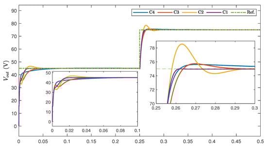
Figure 3.
The output voltages of the FIBC under the four controllers in case of step voltage reference change.
In addition, the system responses under the C3 and C2 control frameworks are significantly improved in comparison to the C4 control approach. However, it should be noted that the proposed control approach achieves the best regulation performance with a shorter settling time and without overshoot by means of the GSTA-based current loop and the GSTA-based observer in the voltage loop. The inductors currents of the FIBC under the four control approaches are presented in Figure 4. As shown in this figure, the inductor current can closely track the current reference generated by the voltage outer loop. However, from Figure 4d, it can be recognized that the GSTA-based controller achieves better control accuracy in comparison to the PI and STA-based controllers. The results confirm the robustness of the proposed control approach in the presence of the step voltage reference change.

Figure 4.
(a) The inductor currents of the FIBC under the C1 controller. (b) The inductor currents of the FIBC under C2 controller. (c) The inductor currents of the FIBC under C3 controller. (d) The inductor currents of the FIBC under proposed controller C4.
5.2.2. Load Step Change
To further examine the anti-disturbance ability of all the controllers, the step change condition in the current load is employed. The utilized load profile is mathematically presented as
The output voltages of the studied FIBC under the four control algorithms are depicted in Figure 5. As shown, under the load change condition, the output voltage of the FIBC significantly reduces when the load increases and vice versa. Since the C4 controller lacks the disturbance compensation mechanism in the outer voltage loop, it exhibits the longest settling time under the presence of the load change condition compared to the three remaining control approaches. In this case, although the C2 controller is capable of reacting faster against the load change, it causes a severe overshoot and consequently a longer settling time in contrast to the C3 and C1 controllers. It is noteworthy that, similar to the above scenario, the recommended control approach possesses the best performance with the smallest settling time and non-overshoot. The simulation results demonstrate the effectiveness and robustness against the load change condition of the suggested control algorithm in comparison with others.
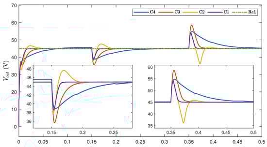
Figure 5.
The output voltage of the FIBC under the four controllers in the case of step load change.
5.2.3. Input Voltage Variation
For evaluating the robustness of the suggested control approach in comparison with the three remaining control algorithms in the case of input voltage variation, a step-changing input voltage is adopted as follows:
The out voltages of the FIBC in the circumstance of the input variation are demonstrated in Figure 6. As depicted in this figure, equivalent to the two above case studies, the C4 controller with the PI control algorithm employed for both inner and outer control loops still attains the longest settling time and the biggest steady-state error. In contrast, the three remaining control approaches are able to achieve better voltage regulation performance. However, it is clearly seen that the proposed control framework obtains the best performance with the smallest overshoot and fast convergence speed in comparison with C3 and C4 control approaches. The results consistently indicate the advantage of the suggested control method and its appropriateness to the voltage regulation problem of the FIBC for fuel cell applications.
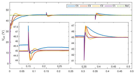
Figure 6.
The output voltages of the FIBC under the four controllers in the case of input voltage variation.
Through the three above case studies, it is worth noting that the proposed control approach can be considered a valuable solution in exactly regulating the output voltage of FIBCs for fuel cell applications, which is more robust against input variation and load change conditions and shorter settling time in comparison with popular existing control methodologies.
6. Conclusions
In this paper, a cascade control structure for stabilizing the output voltage of FIBCs for fuel cell application was developed. The inner current control loop was established using the GSTA, which ensures finite-time stability in spite of the influence of the input variation on the inductor current. Meanwhile, a nonlinear continuous GSTA-based ESO was inherited to estimate the total disturbance caused by input variation and load change in the voltage loop in finite time. Based on this, the lumped disturbance was effectively compensated, and consequently, the high-accuracy voltage control was attained. The schematic of the considered FIBC was constructed using the Simscape Electrical library, and the control algorithm was built in the Simulink environment. Compared to the previous studies, a higher performance of voltage regulation was obtained, which was demonstrated through simulation results. Control realization on an actual FIBC and advanced control techniques for FIBCs will be investigated in future work.
Author Contributions
K.K.A. was the supervisor, providing funding and administrating, and he reviewed and edited the manuscript. M.H.N. performed the investigation, proposed the methodology, analysis, and validations by using the MATLAB/Simulink software for simulations and wrote the original manuscript. All authors have read and agreed to the submitted version of the manuscript.
Funding
This research was financially supported by the “Hydrogen Electric Tram Demonstration Project” through the Ministry of Trade, Industry, and Energy (MOTIE) and the Korea Institute for Advancement of Technology (KIAT) (G02P16110000511), and this work was supported by the “Regional Innovation Strategy (RIS)” through the National Research Foundation of Korea (NRF) funded by the Ministry of Education (MOE) (2021RIS-003).
Institutional Review Board Statement
Not applicable.
Informed Consent Statement
Not applicable.
Data Availability Statement
Not applicable.
Conflicts of Interest
The authors declare no conflict of interest.
Abbreviations
The following abbreviations are used in this paper:
| FC | fuel cell |
| FIBC | floating interleaved boost converter |
| IBC | interleaved boost converter |
| TIBC | two-phased interleaved boost converter |
| STA | super-twisting algorithm |
| GSTA | generalized super-twisting algorithm |
| ESO | extended state observer |
| LESO | linear extended state observer |
| HOESO | high-order extended state Observer |
| ADRC | active disturbance rejection control |
| PSO | partial swarm optimization |
| TDE | time delay estimation |
| PID | proportional-integral-derivative |
References
- Zhang, G.; Li, Q.; Chen, W.; Meng, X.; Deng, H. A coupled power-voltage equilibrium strategy based on droop control for fuel cell/battery/supercapacitor hybrid tramway. Int. J. Hydrogen Energy 2019, 44, 19370–19383. [Google Scholar] [CrossRef]
- Trinh, H.-A.; Truong, H.V.A.; Do, T.C.; Nguyen, M.H.; Phan, V.D.; Ahn, K.K. Optimization-based energy management strategies for hybrid construction machinery: A review. Energy Rep. 2022, 8, 6035–6057. [Google Scholar] [CrossRef]
- Piraino, F.; Fragiacomo, P. A multi-method control strategy for numerically testing a fuel cell-battery-supercapacitor tramway. Energy Convers. Manag. 2020, 225, 113481. [Google Scholar] [CrossRef]
- Wang, Z.; Zheng, Z.; Li, C. A High-Step-Up Low-Ripple and High-Efficiency DC-DC Converter for Fuel-Cell Vehicles. IEEE Trans. Power Electron. 2022, 37, 3555–3569. [Google Scholar] [CrossRef]
- Zhang, G.; Li, Q.; Chen, W.; Meng, X. Synthetic Strategy Combining Speed Self-Adjusting Operation Control and Adaptive Power Allocation for Fuel Cell Hybrid Tramway. IEEE Trans. Ind. Electron. 2021, 68, 1454–1465. [Google Scholar] [CrossRef]
- Sadeghpour, D.; Bauman, J. High-Efficiency Coupled-Inductor Switched-Capacitor Boost Converter With Improved Input Current Ripple. IEEE Trans. Ind. Electron. 2022, 69, 7940–7951. [Google Scholar] [CrossRef]
- Li, H.; Liu, X.; Lu, J. Research on Linear Active Disturbance Rejection Control in DC/DC Boost Converter. Electronics 2019, 8, 1249. [Google Scholar] [CrossRef]
- Hajihosseini, M.; Andalibi, M.; Gheisarnejad, M.; Farsizadeh, H.; Khooban, M.H. DC/DC Power Converter Control-Based Deep Machine Learning Techniques: Real-Time Implementation. IEEE Trans. Power Electron. 2020, 35, 9971–9977. [Google Scholar] [CrossRef]
- Gheisarnejad, M.; Farsizadeh, H.; Khooban, M.H. A Novel Nonlinear Deep Reinforcement Learning Controller for DC–DC Power Buck Converters. IEEE Trans. Ind. Electron. 2021, 68, 6849–6858. [Google Scholar] [CrossRef]
- Li, Q.; Huangfu, Y.; Xu, L.; Wei, J.; Ma, R.; Zhao, D.; Gao, F. An Improved Floating Interleaved Boost Converter With the Zero-Ripple Input Current for Fuel Cell Applications. IEEE Trans. Energy Convers. 2019, 34, 2168–2179. [Google Scholar] [CrossRef]
- Mumtaz, F.; Yahaya, N.Z.; Meraj, S.T.; Singh, B.; Kannan, R.; Ibrahim, O. Review on non-isolated DC-DC converters and their control techniques for renewable energy applications. Ain Shams Eng. J. 2021, 12, 3747–3763. [Google Scholar] [CrossRef]
- Zhang, Y.; Liu, H.; Li, J.; Sumner, M.; Xia, C. DC–DC Boost Converter With a Wide Input Range and High Voltage Gain for Fuel Cell Vehicles. IEEE Trans. Power Electron. 2019, 34, 4100–4111. [Google Scholar] [CrossRef]
- Hao, X.; Salhi, I.; Laghrouche, S.; Ait-Amirat, Y.; Djerdir, A. Backstepping Supertwisting Control of Four-Phase Interleaved Boost Converter for PEM Fuel Cell. IEEE Trans. Power Electron. 2022, 37, 7858–7870. [Google Scholar] [CrossRef]
- Koç, Y.; Birbir, Y.; Bodur, H. Non-isolated high step-up DC/DC converters—An overview. Alex. Eng. J. 2022, 61, 1091–1132. [Google Scholar] [CrossRef]
- Henn, G.A.L.; Silva, R.N.A.L.; Praça, P.P.; Barreto, L.H.S.C.; Oliveira, D.S. Interleaved-Boost Converter With High Voltage Gain. IEEE Trans. Power Electron. 2010, 25, 2753–2761. [Google Scholar] [CrossRef]
- Valdez-Resendiz, J.E.; Mayo-Maldonado, J.C.; Alejo-Reyes, A.; Rosas-Caro, J.C.; Beltran-Carbajal, F. A family of double dual DC-DC converters. In Proceedings of the 11th International Conference on Power Electronics, Machines and Drives (PEMD 2022), Newcastle upon Tyne, UK, 21–23 June 2022; pp. 107–113. [Google Scholar] [CrossRef]
- Zhuo, S.; Xu, L.; Huangfu, Y.; Gaillard, A.; Paire, D.; Gao, F. Robust Adaptive Control of Interleaved Boost Converter for Fuel Cell Application. IEEE Trans. Ind. Appl. 2021, 57, 6603–6610. [Google Scholar] [CrossRef]
- Wang, D.; Wang, Z.; Peng, Z.; Zhang, Y.; Cheng, X.F. A Four-Phase Interleaved Buck-Boost Converter With Changed Load Connection for the Fuel Cell Activation. IEEE Access 2021, 9, 102104–102113. [Google Scholar] [CrossRef]
- Zhuo, S.; Gaillard, A.; Xu, L.; Paire, D.; Gao, F. Extended State Observer-Based Control of DC–DC Converters for Fuel Cell Application. IEEE Trans. Power Electron. 2020, 35, 9923–9932. [Google Scholar] [CrossRef]
- Zhuo, S.; Gaillard, A.; Xu, L.; Liu, C.; Paire, D.; Gao, F. An Observer-Based Switch Open-Circuit Fault Diagnosis of DC–DC Converter for Fuel Cell Application. IEEE Trans. Ind. Appl. 2020, 56, 3159–3167. [Google Scholar] [CrossRef]
- Qi, Z.; Tang, J.; Pei, J.; Shan, L. Fractional Controller Design of a DC-DC Converter for PEMFC. IEEE Access 2020, 8, 120134–120144. [Google Scholar] [CrossRef]
- Kim, S.K.; Ahn, C.K. Proportional-Derivative Voltage Control with Active Damping for DC/DC Boost Converters via Current Sensorless Approach. IEEE Trans. Circuits Syst. II Express Briefs 2021, 68, 737–741. [Google Scholar] [CrossRef]
- Kobaku, T.; Jeyasenthil, R.; Sahoo, S.; Dragicevic, T. Experimental Verification of Robust PID Controller Under Feedforward Framework for a Nonminimum Phase DC–DC Boost Converter. IEEE J. Emerg. Sel. Top. Power Electron. 2021, 9, 3373–3383. [Google Scholar] [CrossRef]
- Mohamed, A.T.; Mahmoud, M.F.; Swief, R.A.; Said, L.A.; Radwan, A.G. Optimal fractional-order PI with DC-DC converter and PV system. Ain Shams Eng. J. 2021, 12, 1895–1906. [Google Scholar] [CrossRef]
- Pereira, L.F.d.S.C.; Batista, E.; de Brito, M.A.G.; Godoy, R.B. A Robustness Analysis of a Fuzzy Fractional Order PID Controller Based on Genetic Algorithm for a DC-DC Boost Converter. Electronics 2022, 11, 1894. [Google Scholar] [CrossRef]
- Wang, Y.-X.; Yu, D.-H.; Chen, S.-A.; Kim, Y.-B. Robust DC/DC converter control for polymer electrolyte membrane fuel cell application. J. Power Sources 2014, 261, 292–305. [Google Scholar] [CrossRef]
- Wang, Y.; Yu, D.; Kim, Y. Robust Time-Delay Control for the DC–DC Boost Converter. IEEE Trans. Ind. Electron. 2014, 61, 4829–4837. [Google Scholar] [CrossRef]
- Wang, Z.; Li, S.; Li, Q. Continuous Nonsingular Terminal Sliding Mode Control of DC–DC Boost Converters Subject to Time-Varying Disturbances. IEEE Trans. Circuits Syst. II Express Briefs 2020, 67, 2552–2556. [Google Scholar] [CrossRef]
- Wang, J.; Luo, W.; Liu, J.; Wu, L. Adaptive Type-2 FNN-Based Dynamic Sliding Mode Control of DC–DC Boost Converters. IEEE Trans. Syst. Man, Cybern. Syst. 2021, 51, 2246–2257. [Google Scholar] [CrossRef]
- Qi, Q.; Ghaderi, D.; Guerrero, J.M. Sliding mode controller-based switched-capacitor-based high DC gain and low voltage stress DC-DC boost converter for photovoltaic applications. Int. J. Electr. Power Energy Syst. 2021, 125, 106496. [Google Scholar] [CrossRef]
- Sartipizadeh, H.; Harirchi, F.; Babakmehr, M.; Dehghanian, P. Robust Model Predictive Control of DC-DC Floating Interleaved Boost Converter with Multiple Uncertainties. IEEE Trans. Energy Convers. 2021, 36, 1403–1412. [Google Scholar] [CrossRef]
- Garcia, F.S.; Pomilio, J.A.; Spiazzi, G. Modeling and Control Design of the Interleaved Double Dual Boost Converter. IEEE Trans. Ind. Electron. 2013, 60, 3283–3290. [Google Scholar] [CrossRef]
- Ma, R.; Xu, L.; Xie, R.; Zhao, D.; Huangfu, Y.; Gao, F. Advanced Robustness Control of DC–DC Converter for Proton Exchange Membrane Fuel Cell Applications. IEEE Trans. Ind. Appl. 2019, 55, 6389–6400. [Google Scholar] [CrossRef]
- Huangfu, Y.; Li, Q.; Xu, L.; Ma, R.; Gao, F. Extended State Observer Based Flatness Control for Fuel Cell Output Series Interleaved Boost Converter. IEEE Trans. Ind. Appl. 2019, 55, 6427–6437. [Google Scholar] [CrossRef]
- Kim, S.K.; Ahn, C.K. Nonlinear Tracking Controller for DC/DC Boost Converter Voltage Control Applications via Energy-Shaping and Invariant Dynamic Surface Approach. IEEE Trans. Circuits Syst. II Express Briefs 2019, 66, 855–1859. [Google Scholar] [CrossRef]
- Ahmad, S.; Ali, A. Unified Disturbance-Estimation-Based Control and Equivalence With IMC and PID: Case Study on a DC–DC Boost Converter. IEEE Trans. Ind. Electron. 2021, 68, 5122–5132. [Google Scholar] [CrossRef]
- Zhuo, S.; Gaillard, A.; Li, Q.; Ma, R.; Paire, D.; Gao, F. Current Ripple Optimization of Four-Phase Floating Interleaved DC–DC Boost Converter Under Switch Fault. IEEE Trans. Ind. Appl. 2020, 56, 4214–4224. [Google Scholar] [CrossRef]
- Zhuo, S.; Gaillard, A.; Xu, L.; Bai, H.; Paire, D.; Gao, F. Enhanced Robust Control of a DC–DC Converter for Fuel Cell Application Based on High-Order Extended State Observer. IEEE Trans. Transp. Electrif. 2020, 6, 278–287. [Google Scholar] [CrossRef]
- Huangfu, Y.; Zhuo, S.; Chen, F.; Pang, S.; Zhao, D.; Gao, F. Robust Voltage Control of Floating Interleaved Boost Converter for Fuel Cell Systems. IEEE Trans. Ind. Appl. 2018, 54, 665–674. [Google Scholar] [CrossRef]
- Yu, J.; Shi, P.; Zhao, L. Finite-time command filtered backstepping control for a class of nonlinear systems. Automatica 2018, 92, 173–180. [Google Scholar] [CrossRef]
- Moreno, J.A. A linear framework for the robust stability analysis of a Generalized Super-Twisting Algorithm. In Proceedings of the 2009 6th International Conference on Electrical Engineering, Computing Science and Automatic Control (CCE), Toluca, Mexico, 10–13 January 2009; pp. 1–6. [Google Scholar] [CrossRef]
- Zhao, L.; Zheng, C.; Wang, Y.; Liu, B. A Finite-Time Control for a Pneumatic Cylinder Servo System Based on a Super-Twisting Extended State Observer. IEEE Trans. Syst. Man, Cybern. Syst. 2021, 51, 1164–1173. [Google Scholar] [CrossRef]


Publisher’s Note: MDPI stays neutral with regard to jurisdictional claims in published maps and institutional affiliations. |
© 2022 by the authors. Licensee MDPI, Basel, Switzerland. This article is an open access article distributed under the terms and conditions of the Creative Commons Attribution (CC BY) license (https://creativecommons.org/licenses/by/4.0/).