Article

Torsional Stress Analysis of Improved Composite Box Girder with Corrugated Steel Webs

School of Civil Engineering, Lanzhou Jiaotong University, Lanzhou 730070, China
*
Author to whom correspondence should be addressed.
Appl. Sci. 2022, 12(22), 11571; https://doi.org/10.3390/app122211571
Submission received: 27 September 2022 / Revised: 10 November 2022 / Accepted: 11 November 2022 / Published: 14 November 2022
(This article belongs to the Section Civil Engineering)

Abstract

:
Based on Umansky’s second theory, this paper studies the torsional stress of an improved composite box girder with corrugated steel webs and considers the effective elastic modulus of the converted section. The calculation formulas of the torsional stress of a single-box multi-cell-improved composite box girder with corrugated steel webs were derived, the initial parameter solution of the generalized displacement and internal force under the restrained torsion were obtained through a model test and finite element simulation, the correctness of the theoretical formulas were verified, the distribution forms of the torsional stress on the box girder section were analyzed, and the effects of the height/width ratio, the width ratio of the cantilever plate, and the thickness of the bottom steel flange on the torsional stress were studied. The results show that the theoretical values and finite element values are in good agreement with the measured values for the torsional stress at each measuring point, and the errors are within 10%. The torsional normal stress of the bottom steel flange of the box girder is much greater than that of the top concrete flange, and the corrugated steel web hardly bears the torsional normal stress. The total shear stress of the box girder is mainly borne by the corrugated steel web on both sides and the bottom steel flange and less by the top concrete flange. The greater height/width ratio, the greater the difference between the torsional normal stress of the bottom steel flange and the top concrete flange. For a box girder with small height/width ratio, the total shear stress of each plate is significantly greater than that of a box girder with large height/width ratio.

1. Introduction

Compared with conventional concrete box girders, a composite box girder with corrugated steel webs has several advantages, including that it is lightweight, has a convenient construction process, improved prestress efficiency, and lower probability of developing web cracks. When a corrugated steel web is used to replace the concrete web of box girders, the reduction of the web thickness reduces the torsional stiffness of the box girder. Previous studies have shown that the reduction in the torsional stiffness is approximately 60~70% [1]. Therefore, torsional loads, such as those resulting from eccentric loads, could have a more prominent effect on composite box girders with corrugated steel webs. This effect may, in turn, impact the structural safety of those girders.
In recent years, several research studies have been introduced to calculate the torsional performance of composite box girders with corrugated steel webs [2,3,4,5]. Among them, Ma et al. [6] and Deng et al. [7] derived differential equations based on Umansky’s second theory to calculate the torsion and distortion of composite box girders with corrugated steel webs. Mo et al. [8,9] applied the softened truss theory to the torsion analysis of composite box girders with corrugated steel webs and proposed the corresponding torsion design method. Ko et al. [10] proposed an improved softened truss analysis model that fully considered the tensile characteristics of the concrete, and the model was validated by physical tests, as well as a finite element analysis. Shen et al. [1] developed an analytical model to determine the torsional stress of composite box girders on the basis of two stakes, and the whole torque/twist curve of composite box girders with corrugated steel webs under pure torque was obtained. Ding et al. [11,12] and Jiang et al. [13] studied the torsional mechanism and the torsional strength by using a torsional test of a Prestressed Concrete (PC) composite box girder model with corrugated steel webs. Jeng et al. [14,15] applied the softened membrane under shear action to the torsion member and proposed the softened membrane model under the pure torsion action. Zhou et al. [16] established a full-range analytical model for PC composite box girders with corrugated steel webs based on the theory of the softened membrane. Among the above theoretical analyses, the analysis based on Umansky’s second theory is the most common. This theory is simple, easy to understand, and mature, and the calculation results can meet the requirements of engineering error [3]. When analyzing the torsional effect of composite box girders with corrugated steel webs by using Umansky’s second theory, the composite section is converted into the section of the same material according to the ratio of the shear modulus of the steel and concrete, and then calculate it as a thin-walled box girder. However, the elastic modulus of the converted section is not completely equal, and the elastic modulus of the web is different from that of the top and bottom flanges, which leads to a large difference between the calculated results and the actual results of the box girder [17,18].
The above studies mainly focused on traditional composite box girders with corrugated steel webs; however, there are fewer studies related to improved composite box girders with corrugated steel webs with a steel bottom plate instead of the conventional concrete bottom plate [19,20,21]. This type of box girder has several advantages, including its light weight, good seismic performance, low cost, and the reduced probability of developing bottom cracks. However, the reduction of the thickness of the bottom plate also reduces the torsional stiffness of the section, and, therefore, the torsional stress of the box girder may be impacted under the eccentric load. This paper provides a methodology to calculate the torsional stress in a single-box multi-cell-improved composite box girder with corrugated steel webs. The methodology is based on Umansky’s second theory and considers the effective elastic modulus of the converted section. The developed method was validated using physical testing of a model beam, as well as a finite element. The paper also investigates the effects of the height/width ratio, the width ratio of the cantilever plate, and the thickness of the bottom steel flange on the torsional stress of the box girder. The conclusions obtained in this paper can provide a reference for the design and construction of this kind of box girder.

2. Research Methods

2.1. Mechanical Properties of a Corrugated Steel Web

2.1.1. Longitudinal Modulus of Elasticity

The geometric shape of a corrugated steel web is shown in Figure 1. Since the corrugated steel web can be freely deformed along its longitudinal axis, its longitudinal modulus of elasticity is significantly low. The longitudinal modulus of elasticity may be calculated as [2]:
E w = a w + b w 4 a w ( t w h w ) 2 E s
where E s is the elastic modulus of the steel; a w is the length of the straight plate; b w is the projection length of the inclined plate; α is the acute angle between the straight plate and inclined plate, and t w and h w are the thickness and height of the corrugated steel web, respectively.

2.1.2. Effective Shear Modulus

The corrugated steel web is equivalent to an orthotropic plate, and its effective shear modulus is less than that of the steel. The specific expression is as follows [2]:
G e = G s ( a w + b w ) a w + b w sec α
in which
G s = E s 2 ( 1 + μ )
where G s is the shear modulus of the steel; μ is Poisson’s ratio of the steel, and the other parameters are shown in Figure 1.

2.1.3. Section Conversion

The constrained torsional analysis of the structure is generally based on the principles of a homogeneous section. Considering that a box girder mainly bears the shear stress during the torsion, the composite section is converted to a full-steel section according to the shear modulus ratio [22]. The conversion formula is as follows:
t so = G c G s t o t sw = G e G s t w
where G c is the shear modulus of the concrete; t o is the thickness of the top concrete flange; t w is the thickness of the corrugated steel web; t so is the thickness of the top steel flange, and t sw is the thickness of the flat steel web.
After the top concrete flange and corrugated steel web are converted into a flat steel plate with a certain thickness, according to the principle of equivalent bending stiffness, their corresponding effective elastic moduli are as follows:
E eo = t o t so E c E ew = t w t sw E w
where E eo is the effective elastic modulus of the top steel flange; E ew is the effective elastic modulus of the flat steel web.
The ratio of the effective elastic modulus of the top steel flange and flat steel web to the elastic modulus of the steel is:
λ 1 = E eo E s λ 2 = E ew E s

2.2. Torsional Stress Analysis

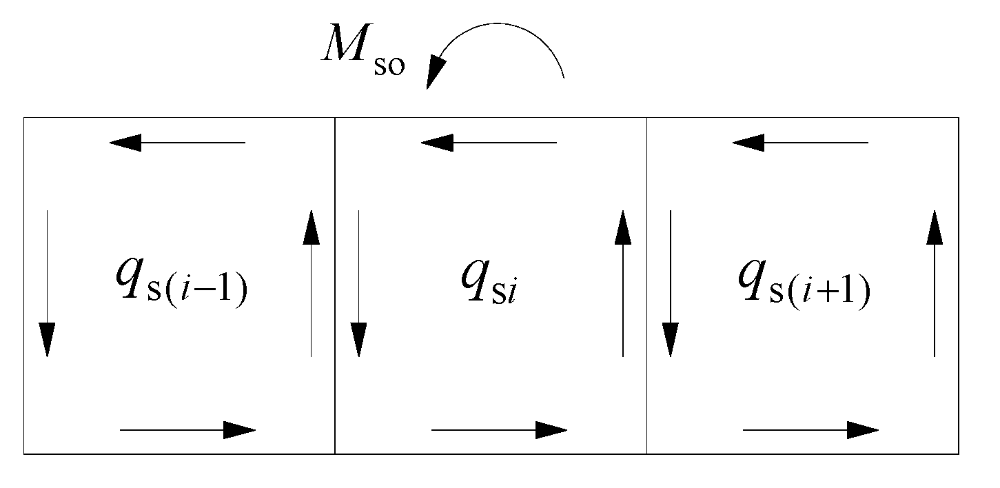
2.2.1. Free Torsional Shear Stress

When a box girder is free to twist, the longitudinal deformation of each fiber in the section is free; therefore, there is no longitudinal normal stress in the section since there is only free torsional shear stress. As shown in Figure 2, the torque acting on the closed section of a box girder is M so , and each cell has the same twist rate, θ , in the free torsion, and the relationship between the shear flow and twist rate in each cell is as follows [23]:
q s i i d s t q s k i , k d s t = G s θ Ω i
where i is the integral around cell i ; i , k is the integral within the web shared by cells i and k ; Ω i is twice the area enclosed by the midline of the wall of cell i ; k is the adjacent cell of cell i ; k = i ± 1 ; q s i is the free torsional shear flow of cell i ; t is the converted thickness of the corresponding top plate, bottom plate, and web.
By balancing the internal and external forces, the sum of the torque generated by the shear flow in each cell is equal to the total torque of the section. The specific relationship is as follows:
i = 1 n q s i Ω i = M so
According to Equations (7) and (8), the free torsional shear flow and twist rate of each cell in a box girder can be obtained.
Therefore, the free torsional shear stress of a box girder section is given by:
τ s = q ¯ s t
where q ¯ s is the actual free torsional shear flow, q ¯ s = q s i q s k ( Common   cell   wall ) q s i ( Independent   cell   wall ) 0 ( Cantilever   plate )
For a cantilever plate, the free torsional shear stress in the center line of the cantilever plate is zero, because the free torsional shear flow cannot be formed on the center line of the open section, and there is only secondary shear flow.
According to the relationship between torque and twist rates [23], the torsional moment of inertia of the closed section of a box girder can be obtained as:
I do = i = 1 n q s i Ω i / ( G s θ )
The torsional moment of inertia of the cantilever plate is given by [24]:
I dc = 1 3 j = 1 2 c t so 3
where c is the length of the cantilever plate on one side.
The total torque in a box girder-free torsion can be written as:
M z = G s I d θ
where I d is torsion moment of the inertia of the box girder section, I d = I do + I dc .

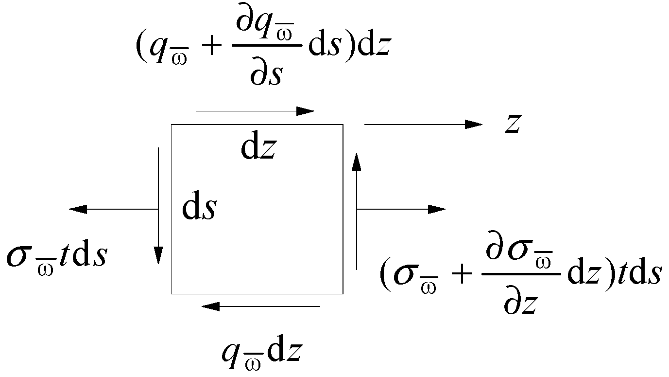
2.2.2. Restrained Torsional Normal Stress

According to Umansky’s second theory and using basic assumptions [23], the longitudinal warping displacement of a closed section under restrained torsion is given by:
u ( z , s ) = u 0 ( z ) ω ¯ ( s ) β ( z )
where u 0 is the longitudinal displacement at the fictitious notch of the closed section; ω ¯ is the generalized main sectorial coordinate, and β is the generalized warping displacement.
Taking the derivative of Equation (13), the axial strain of the closed section can be obtained as follows:
ε ( z , s ) = u z = u 0 ( z ) ω ¯ ( s ) β ( z )
In a balanced state, u 0 ( z ) = 0 ; therefore, the restrained torsional normal stress in the box girder section is calculated as:
σ ω ¯ = λ 1 E s ω ¯ β ( Top   steel   flange ) λ 2 E s ω ¯ β ( Flat   steel   web ) E s ω ¯ β ( Bottom   steel   flange )
Equation (15) gives the restrained torsional normal stress of the converted section. For the restrained torsional normal stress of the original section, it should also be calculated according to the ratio of the elastic modulus of the original section to the effective elastic modulus of the converted section.
According to the definition of torsional bi-moment and Equation (15), it can be concluded that [25]:
B ω ¯ = σ ω ¯ ω ¯ t d s = E s I ω ¯ β
where I ω ¯ is the generalized main sectorial moment of inertia, I ω ¯ = λ 1 A u ω ¯ 2 d A + λ 2 A w ω ¯ 2 d A + A b ω ¯ 2 d A ; A u is the sectional area of the top steel flange; A w is the total sectional area of the flat steel web, and A b is the sectional area of the bottom steel flange.

2.2.3. Restrained Torsional Shear Stress

According to reference [26], when a box girder is restrained to twist, the total shear flow, q , of a box girder with a closed section is the sum of the free torsional shear flow, q s , and the secondary shear flow, q ω ¯ , which balances the warping normal stress. This may be given as:
q = q s + q ω ¯
As shown in Figure 3, a micro-element is taken from the cell wall. By balancing the forces, it can be concluded that [17]:
σ ω ¯ z t + q ω ¯ s = 0
From Equation (18), the secondary shear flow is calculated as:
q ω ¯ = E s β S ^ ω ¯ + q ω ¯ 0
where q ω ¯ 0 is the additional shear flow at the fictitious notch of a closed section; S ^ ω ¯ is the converted sectorial static moment.
The converted sectorial static moment of the closed section can be obtained by:
S ^ ω ¯ = λ 1 S ω ¯ ( Top   steel   flange ) λ 2 S ω ¯ ( Flat   steel   web ) S ω ¯ ( Bottom   steel   flange )
where S ω ¯ is the sectorial static moment, S ω ¯ = 0 s ω ¯ t d s .
Since each cell of the box girder section is closed, and the additional shear flow of each cell at the fictitious notch is not zero, the value should be determined according to the continuity condition of warping displacement. The continuity condition of the warping displacement of a closed section may be expressed as follows [26]:
γ ω ¯ d s = q ω ¯ G s t d s = 0
The deformation coordination condition at the fictitious notch of cell i may be expressed as:
E s β i S ^ ω ¯ G s t d s i , k S ^ ω ¯ G s t d s + i q ω ¯ 0 i G s t d s i , k q ω ¯ 0 k G s t d s = 0
where q ω ¯ 0 i is the additional shear flow at the fictitious notch of cell i .
For a multi-cell box girder, multiple linear equations may be obtained according to Equation (22), which can solve the additional shear flow of any cell.
Let:
q ω ¯ 0 i = E s β S i
where S i is the additional sectorial static moment of cell i .
The secondary shear flow in the box girder section is:
q ω ¯ = M ω ¯ I ω ¯ S ¯ ω ¯
where M ω ¯ is the secondary torque, M ω ¯ = E s I ω ¯ β ; S ¯ ω ¯ is the generalized sectorial static moment, S ¯ ω ¯ = S i S k ( Common   cell   wall ) S ^ ω ¯ + S i ( Independent   cell   wall ) λ 1 S ω ¯ ( Cantilever   plate ) .
The total shear stress of the box girder section is calculated as:
τ = τ s + τ ω ¯ = q ¯ s t M ω ¯ I ω ¯ t S ¯ ω ¯
In Equation (25), t is the thickness of the original section.

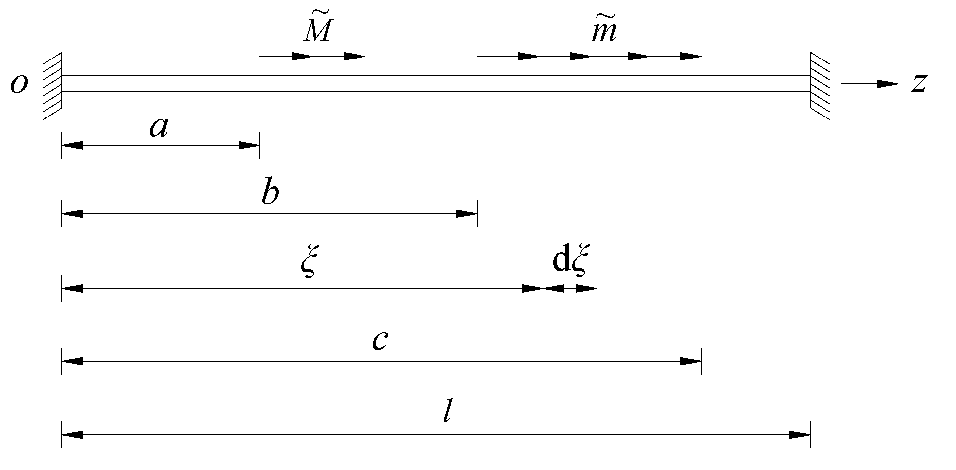
2.2.4. Solving the Torsional Differential Equations

According to Umansky’s second theory [23], the restrained torsional differential equation about the torsional angle, θ , is given as follows:
θ ( 4 ) k 2 θ = μ m z E s I ω ¯
where k 2 is the characteristic parameter under the restrained torsion, k 2 = μ G s I d E s I ω ¯ ; μ is the restrained coefficient of the section, μ = 1 I d I ρ ; I ρ is the polar moment of inertia; m z is the concentration of the torque load.
The relationship between the generalized warping displacement, β , and the torsional angle, θ , is given by:
β = 1 μ θ M z G s I ρ
where M z is the total torque of the box girder, M z = M s + M ω ¯ ; M s is the free torsional torque.
The initial parameter method is used to solve the differential equation of the constrained torsion. Firstly, four initial parameters θ 0 , β 0 , B 0 , and M 0 are defined as the torsional angle, generalized warping displacement, torsional bi-moment, and total torque at the starting end of the box girder, respectively. Let m z = 0 in Equation (26), and the initial parameter expressions of the torsional angle, generalized warping displacement, torsional bi-moment, and total torque of any section may be obtained as follows:
θ ( z ) = θ 0 + μ β 0 k sinh k z + B 0 G s I d ( 1 cosh k z ) + M 0 G s I d ( z μ k sinh k z ) β ( z ) = β 0 cosh k z k B 0 μ G s I d sinh k z + M 0 G s I d ( 1 cosh k z ) B ω ¯ ( z ) = μ β 0 G I d k sinh k z + B 0 cosh k z + μ M 0 k sinh k z M z ( z ) = M 0
The boundary condition [27]:
(1) The fixed end:
θ = 0 β = 0
(2) The simply supported end:
θ = 0 β = 0
(3) The free end:
G s I d θ E s I ω ¯ β = 0 β = 0
In Equation (28), the four initial parameters are determined by the boundary condition, and its solution is suitable for the case of no load on the span of the box girder. As shown in Figure 4, when there is an external torque load on the span, the initial parameters are given by:
θ ( z ) = θ 0 + μ β 0 k sinh k z + B 0 G s I d ( 1 cosh k z ) + M 0 k G s I d ( k z μ sinh k z ) M ˜ k G s I d a k ( z a ) μ sinh k ( z a ) b z m ˜ k G s I d k ( z ξ ) μ sinh k ( z ξ ) d ξ b β ( z ) = β 0 cosh k z k B 0 μ G s I d sinh k z + M 0 G s I d ( 1 cosh k z ) M ˜ G s I d a 1 cosh k ( z a ) b z m ˜ G s I d 1 cosh k ( z ξ ) d ξ b B ω ¯ ( z ) = μ G s I d β 0 k sinh k z + B 0 cosh k z + μ M 0 k sinh k z μ M ˜ k a sinh k ( z a ) b z μ m ˜ k sinh k ( z ξ ) d ξ b M z ( z ) = M 0 M ˜ a b z m ˜ d ξ b
where symbol a and symbol b respectively indicate that this item is included only when z > a or z > b , when z > c , and the upper limit of the integral is changed to c .

2.3. Physical Testing

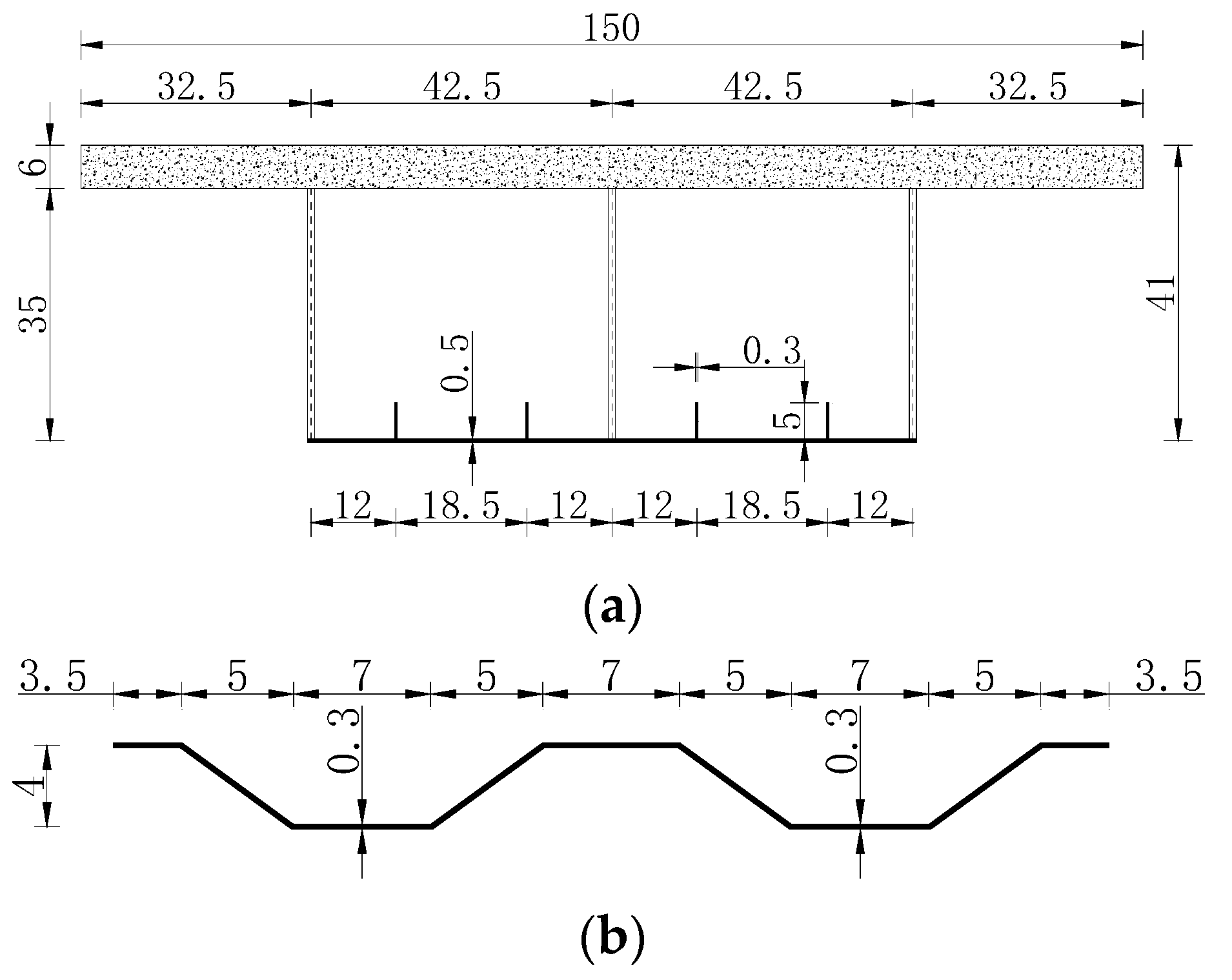
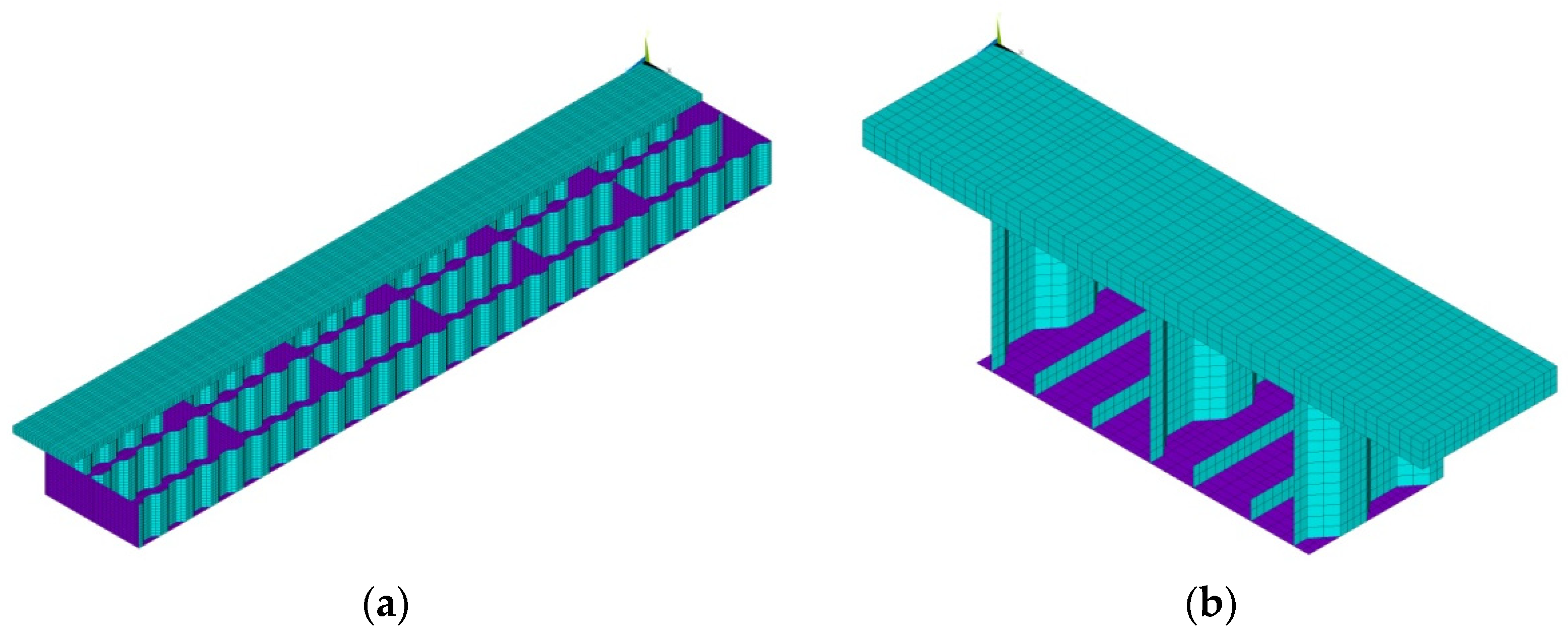
2.3.1. Model Beam Size

The total length of an improved composite box girder model with corrugated steel webs is 6 m, the calculated span is 5.8 m, and the beam height is 0.41 m, which is in the form of a single-box twin-cell with equal sections. The width of the top flange is 1.5 m, and the thickness is 6 cm. It is reinforced concrete with grade I ordinary reinforcement. The concrete grade is C55 (C55 indicates that the nominal cube compressive strength standard value of the concrete is 55 MPa), the elastic modulus is 35.5 GPa, and Poisson’s ratio is 0.2. The width of the bottom flange is 0.85 m, and the thickness is 5 mm. Four columns of longitudinal stiffeners are welded on the bottom flange. Two end diaphragms and three middle diaphragms are arranged in the box girder. The steel grade of the corrugated web, bottom flange, diaphragm, and stiffener is Q345 (Q345 indicates that the yield strength of the steel is 345 MPa), the elastic modulus is 206 GPa, and Poisson’s ratio is 0.28. The model beam size is shown in Figure 5.
A finite element model of the model beam was established by using the software ANSYS 15.0. According to the pre-processing module, calculation and analysis module, and post-processing module of the software, one, firstly, defines the material properties of the steel and concrete and establishes the constitutive relationship of the steel and concrete. Then, establish the geometric model of the model beam according to the model beam size, as shown in Figure 5. Finally, select the appropriate element type to mesh the geometric model, where the top flange is simulated by a solid element SOLID65, the steel box is simulated by a shell element SHELL63, and the solid element and shell element are connected by common nodes. The mass element MASS21 is defined at the torsion center of the mid-span section, the nodes of the mid-span section are coupled with the mass element to form a rigid region, and the pure torque loading at the mid-span of the box girder is simulated by applying the torque to the mass element. Fixed constraints are adopted at both ends of the box girder. The finite element model is shown in Figure 6.

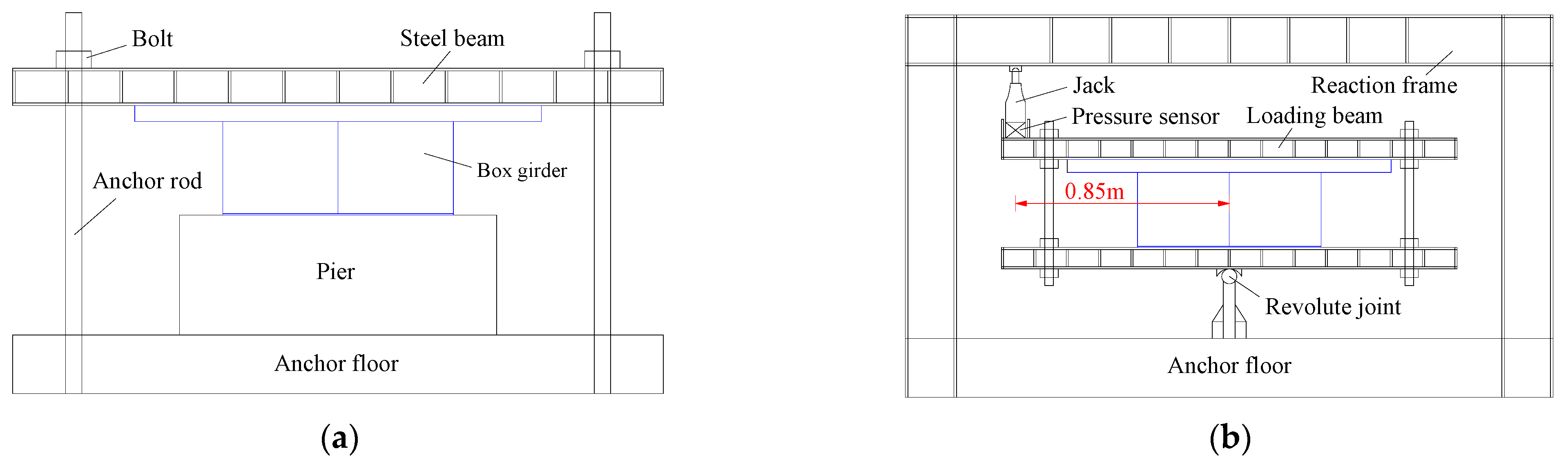
2.3.2. Loading Device

According to the pure torsion loading device in reference [28], firstly, two steel beams are used to fix both ends of the model beam, and two loading beams are used to clamp the mid-span section so that the mid-span section can rotate freely around the revolute joint at the lower end under the action of the loading beam. A hydraulic jack applies a vertical load at the end of the loading beam to form a torque, the arm length of the loading beam is 0.85 m, and the applied load is controlled by the pressure sensor. Several components of this device were manufactured by Lanzhou Zhicheng Machinery Manufacturing Co., Ltd. (Lanzhou, China). The test loading device is shown in Figure 7.
For this test, torsion was applied to a box girder that rotated around the revolute joint at the lower end of the loading beam, and not the actual torsion center of the box girder. This arrangement may cause certain errors if the pure torsion test of the box girder has been applied. Considering that the torsional angle of the model test is very small, this type of error can be ignored. The test-loading photos are shown in Figure 8.

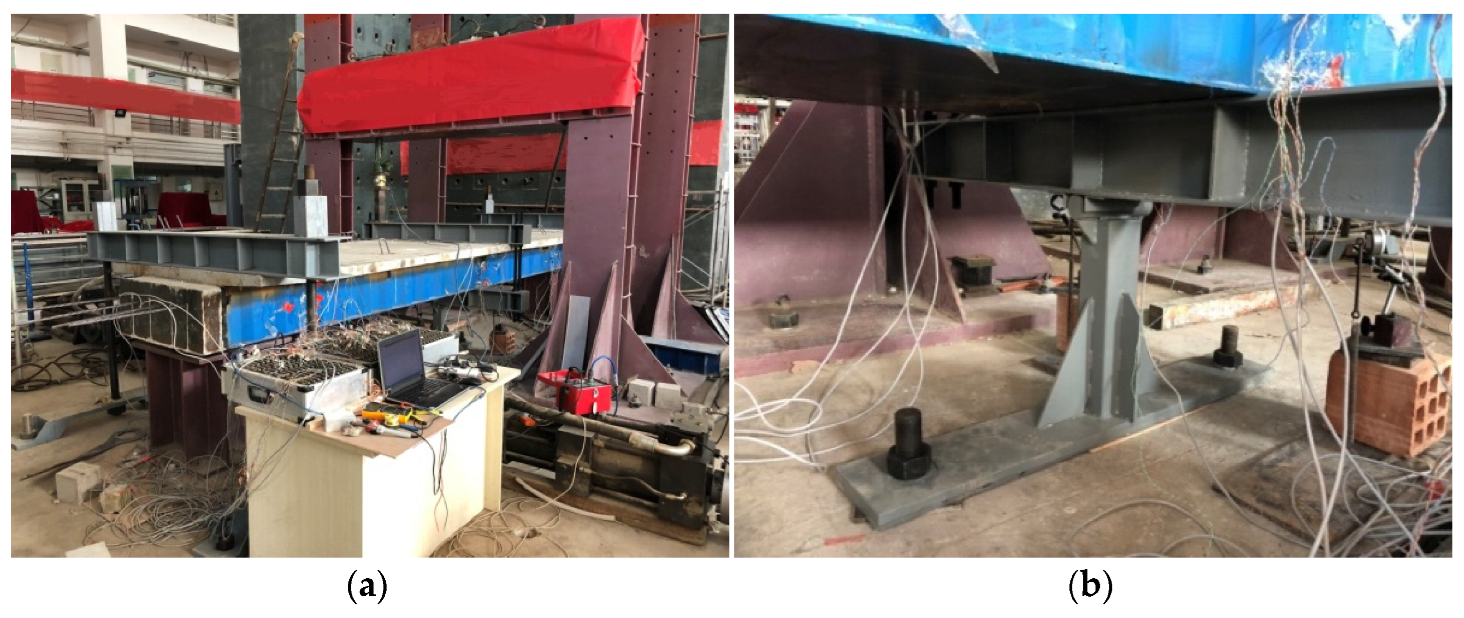
2.3.3. Test Arrangement

Section A, located 10 cm away from the mid-span, and Section B, at a 1/8 span, were selected as the main test sections. In each test section, the top concrete flange was arranged with 7 measuring points; the bottom steel flange was arranged with 5 measuring points, and the corrugated steel web on both sides was arranged with 6 measuring points along the vertical. The normal strain and shear strain of each measuring point were measured by strain gauges, the data were collected through a DH3816 static strain monitor, and the torsional stress of each measuring point could be obtained according to the relationship between the stress and strain. The layout of the test section and measuring points is shown in Figure 9.

3. Results & Discussion

3.1. Results Analysis

3.1.1. Torsional Stress Comparison

In the test, the jack load, P = 10   kN , and the external torque, M ˜ = 8.5   kN m , the restrained torsional normal stress at measuring points S1, S2, and X1, and the total shear stress at measuring points S4, W2, and X3 on the test section were selected as the research objects. The comparison of the measured values, T t , theoretical values, T h , and finite element values, T e , of the torsional stress at each measuring point are shown in Table 1.
It can be seen from Table 1 that the theoretical values and finite element values of each measuring point of the test section are in good agreement with the measured values, and the error in each measuring point is within 10%, which validates the calculation method provided in this paper.
It can be seen from reference [18] that the error between the calculation result of the previous theoretical formula and the measured value is relatively large, while the error between the calculation results in this paper and the measured value is smaller, and the calculation accuracy is higher.

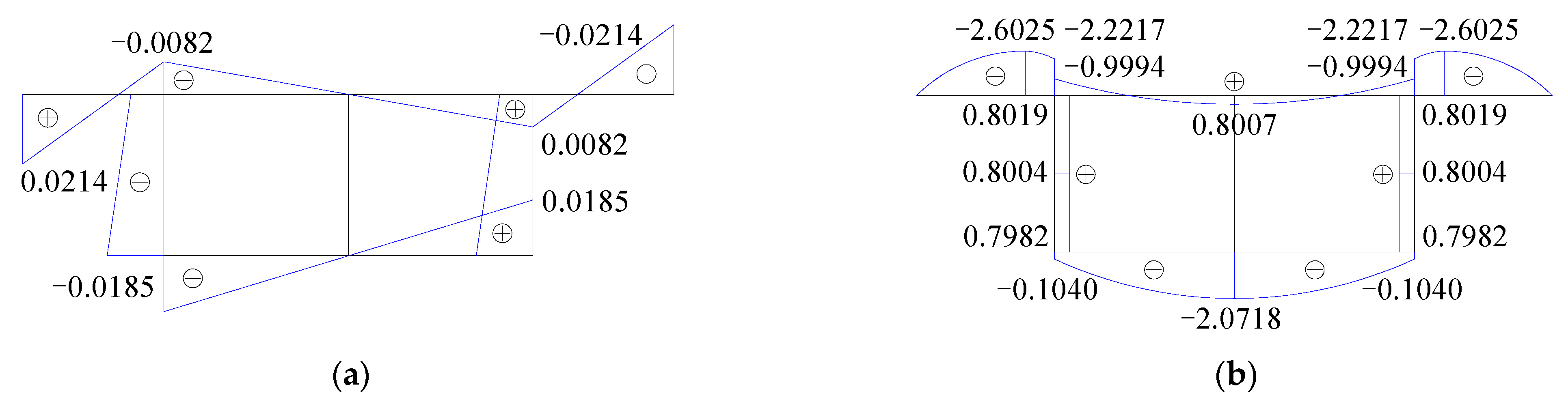
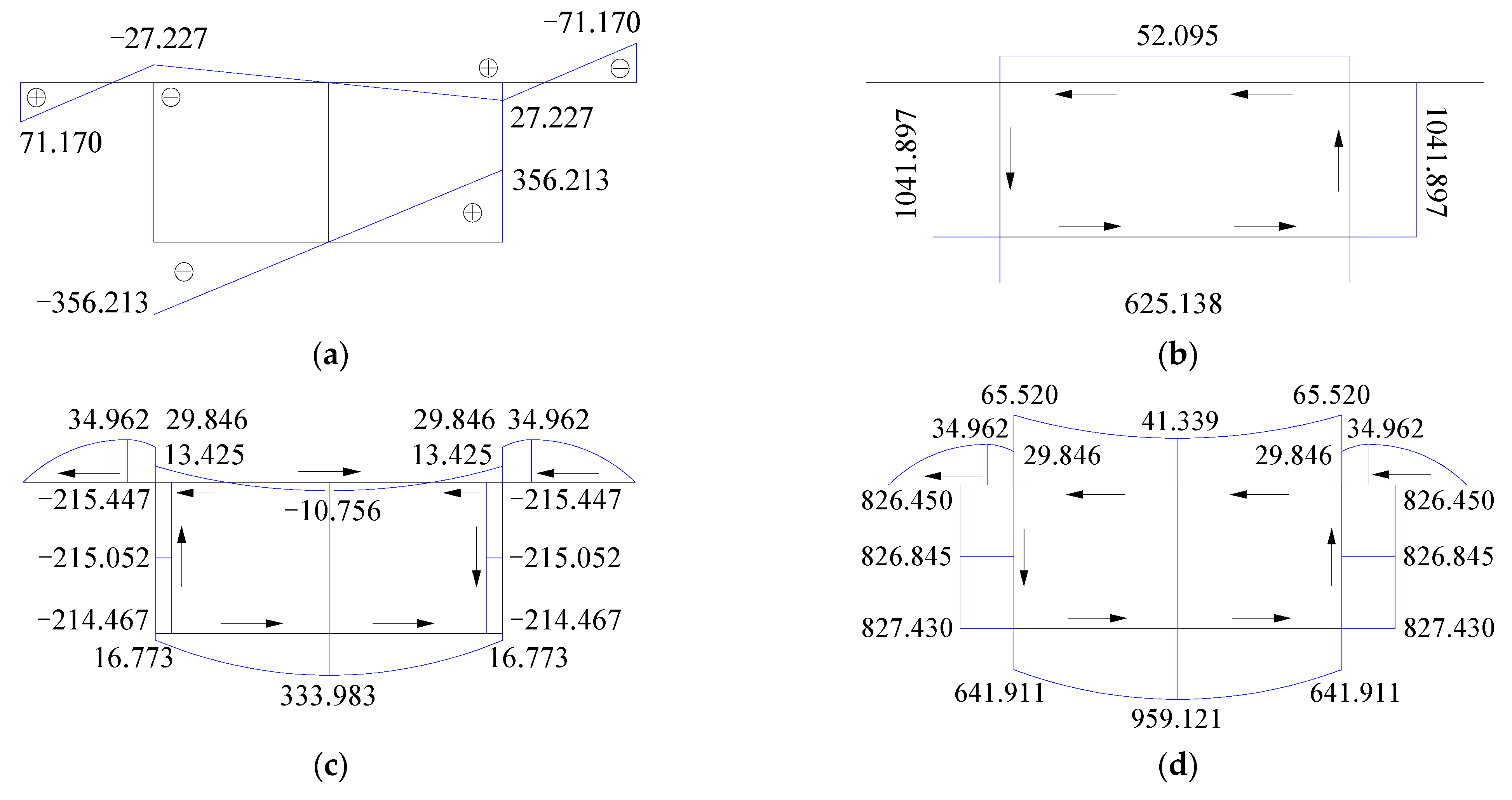
3.1.2. Distribution of Torsional Stress

After the model beam section is converted into a full-steel section, the thickness of the top steel flange is 1.103 cm, the thickness of the flat steel web is 0.268 cm, and the torsional center of the section is calculated to be 9.110 cm below the center of the top steel flange. The generalized main sectorial moment of inertia, I ω ¯ = 1.4682 × 10 6   m 6 , the torsional moment of inertia, I d = 7.7945 × 10 4   m 4 , the polar moment of inertia, I ρ = 8.5156 × 10 4   m 4 , the generalized main sectorial coordinate, ω ¯ , and the generalized sectorial static moment, S ¯ ω ¯ , of the full-steel section are shown in Figure 10.
When an external torque, M ˜ = 4.25   kN m , is applied, the restrained torsional normal stress, σ ω ¯ , free torsional shear stress, τ s , secondary shear stress, τ ω ¯ , and total shear stress, τ , of Section A can be obtained according to the geometric characteristics of the section, as shown in Figure 11.
It can be seen from Figure 11 that the torsional normal stress of the bottom steel flange of the box girder is significantly greater than that of the top concrete flange, and the torsional normal stress generated by the corrugated steel web is almost negligible. The free torsional shear stress exists only on the closed section, and it is uniformly distributed on each individual plate. The secondary shear stress generated by the corrugated steel web is large and basically consistent along the vertical direction. This is because the corrugated steel web has not only the secondary shear flow generated by balancing its own warping normal stress, but also the secondary shear flow generated by balancing the warping normal stress of the top concrete flange and bottom steel flange; therefore, the secondary shear stress on the corrugated steel web is large. The total shear stress of the box girder is mainly borne by the corrugated steel web on both sides and bottom steel flange, and less by the top concrete flange. The main reason is that the thickness of the corrugated steel web and bottom steel flange is thin, so that the shear flow shared by them per unit thickness is large. For the single-box twin-cell section, the shear flow of the adjacent two cells counteracts each other on the corrugated steel web in the middle, so the corrugated steel web in the middle is not subject to any shear stress.

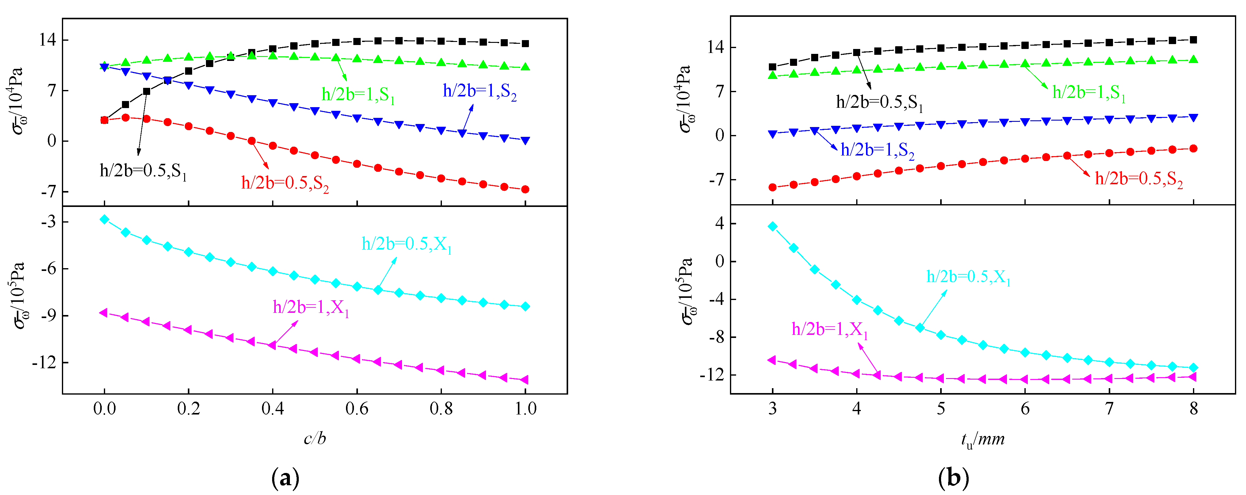
3.2. Parameter Analysis

In order to study the influence of parameter changes on the torsional stress of the improved composite box girder with corrugated steel webs, based on the model beam, the width of each cell, b , is 0.425 m, a beam height, h , is taken as 0.425 and 0.85 m respectively, and the height/width ratio, h / 2 b , is taken as 0.5 and 1 respectively. The width ratio of the cantilever plate, c / b , was increases by 0.05 from 0 to 1. This means that the width of the cantilever plate, c , was increased from 0 to 0.425 m. The thickness of the bottom steel flange, t u , was increased from 3 mm to 8 mm using 0.5 mm increments. Under the external torque of M ˜ = 8.5   kN m , the changes of torsional normal stress at measuring points S1, S2 and X1 on Section A are shown in Figure 12. The changes of the total shear stress at measuring points S4, W2 and X3 on Section A are shown in Figure 13.
It can be seen from Figure 12 that with the increase of the width ratio of the cantilever plate and the thickness of the bottom steel flange, the torsional normal stress at each measuring point shows different trends, and there is tensile and compressive stress conversion at some measuring points. Under the same height/width ratio, the torsional normal stress at measuring point X1 is significantly larger than that at measuring points S1 and S2. With the increase of the height/width ratio, the difference between the torsional normal stress at measuring point X1 and that at measuring points S1 and S2 becomes larger. The change of the width ratio of the cantilever plate has a significant impact on the torsional normal stress at measuring points S1, S2, and X1. The change of the thickness of the bottom steel flange also has a significant impact on the torsional normal stress at measuring point X1, but the impact is small on the torsional normal stress at measuring points S1 and S2.
It can be seen from Figure 13 that with the increase of the width ratio of the cantilever plate and the thickness of the bottom steel flange, the total shear stress of the box girder section changes along the positive direction (counterclockwise). For a box girder with a small height/width ratio, the total shear stress is significantly greater than that of a box girder with a large height/width ratio. With the increase of the width ratio of the cantilever plate, the total shear stress at measuring point W2 decreases gradually, and the total shear stress at measuring point X3 increases gradually. With the increase of the thickness of the bottom steel flange, the total shear stress at measuring point W2 changes relatively gently, and the total shear stress at measuring point X3 decreases gradually. Since the total shear stress at measuring point S4 is smaller than that at measuring points W2 and X3, the influence of the parameter change on it is not obvious.

4. Conclusions

By analyzing the torsional stress of an improved composite box girder with corrugated steel webs, it can be concluded that:
(1) By using the principles of Umansky’s second theory and considering the effective elastic modulus of the converted section, the calculation formulas of the torsional stress of an improved composite box girder with corrugated steel webs were derived. The method was validated by using physical torsional testing and finite element simulation, the error in each measuring point was found to be less than 10%, and the calculation accuracy was improved.
(2) From the distribution of the torsional stress, it can be seen that the torsional normal stress of the bottom steel flange of the box girder is much greater than that of the top concrete flange and the torsional normal stress produced by the corrugated steel web was very small and can be ignored. The secondary shear stress produced by the corrugated steel web was large and basically consistent along the vertical direction. The total shear stress of the box girder was mainly supported by the corrugated steel web on both sides and the bottom steel flange, and less by the top concrete flange.
(3) With the increase of the width ratio of the cantilever plate and the thickness of the bottom steel flange, the torsional shear stress of each measuring point changed along the positive direction(counterclockwise), and the torsional normal stress of some of the measuring points had the conversion of the tensile and compressive stress. The greater the height/width ratio, the greater the difference between the torsional normal stress at the bottom steel flange and that at the top concrete flange. For a box girder with a small height/width ratio, the total shear stress was significantly greater than that of a box girder with a large height/width ratio.

Author Contributions

Conceptualization, A.Q. and S.L.; Methodology, A.Q.; Software, A.Q.; Validation, M.C. and F.W.; Formal Analysis, A.Q.; Investigation, B.G.; Resources, S.L.; Data Curation, A.Q.; Writing—Original Draft Preparation, A.Q.; Writing—Review and Editing, A.Q.; Visualization, M.C. and F.W.; Supervision, B.G.; Project Administration, S.L.; Funding Acquisition, S.L. All authors have read and agreed to the published version of the manuscript.

Funding

This research was funded by the National Natural Science Foundation of China (Grant Nos. 51568036, 51868040, and 52268027); the Natural Science Foundation of Sichuan Province (Grant No. 2022NSFSC0427).

Institutional Review Board Statement

Not applicable.

Informed Consent Statement

Not applicable.

Data Availability Statement

The date presented in this study are available on request from the corresponding author.

Conflicts of Interest

The authors declare no conflict of interest.

References

  1. Shen, K.J.; Wan, S.; Jiang, Z.W.; Mo, Y.L. Whole process analysis on pure torsional behavior of concrete composite box girders with corrugated steel webs. J. Southeast Univ. (Nat. Sci. Ed.) 2017, 47, 112–117. [Google Scholar]
  2. Yang, B.W.; Li, Y.L.; Wan, S.; Zhang, J.D. Stress analysis of box girder with corrugate steel webs under torsion. J. South China Univ. Technol. (Nat. Sci. Ed.) 2012, 40, 19–22+34. [Google Scholar]
  3. Li, H.J. Experimental Study and Analysis on Torsion and Distortion of Box-Girder with Corrugated Steel Webs. Ph.D. Thesis, Southeast University, Nanjing, China, 2003. [Google Scholar]
  4. Kato, H.; Nishimura, N. Practical analysis methods for continuous girder and cable stayed bridges composed of beams with corrugated steel webs. Earthq. Eng. Struct. Dyn. 2004, 21, 207–222. [Google Scholar] [CrossRef] [Green Version]
  5. Sayed-Ahmed, E.Y. Behaviour of steel and (or) composite girders with corrugated steel webs. Can. J. Civ. Eng. 2001, 28, 656–672. [Google Scholar] [CrossRef]
  6. Ma, L.; Wan, S.; Jiang, Z.W. Research on torsion and distortion performance of single box double-cell girder with corrugated steel webs. China J. Highw. Transp. 2016, 29, 77–85. [Google Scholar]
  7. Deng, W.Q.; Mao, Z.L.; Liu, D.; Zhang, J.D. Analysis and experimental study of torsion and distortion of single box three-cell cantilever girder with corrugated steel webs. J. Build. Struct. 2020, 41, 173–181. [Google Scholar]
  8. Mo, Y.L.; Jeng, C.H.; Chang, Y.S. Torsional behavior of prestressed concrete box-girder bridges with corrugated steel webs. ACI Struct. J. 2000, 97, 849–859. [Google Scholar]
  9. Mo, Y.L.; Fan, Y.L. Torsional design of hybrid concrete box girders. J. Bridge Eng. 2006, 11, 329–339. [Google Scholar] [CrossRef]
  10. Ko, H.J.; Moon, J.; Shin, Y.W.; Lee, H.E. Non-linear analyses model for composite box-girders with corrugated steel webs under torsion. Steel Compos. Struct. 2013, 14, 409–429. [Google Scholar] [CrossRef] [Green Version]
  11. Ding, Y.; Jiang, K.B.; Liu, Y.W. Nonlinear analysis for PC box-girder with corrugated steel webs under pure torsion. Thin Wall. Struct. 2012, 51, 167–173. [Google Scholar] [CrossRef]
  12. Ding, Y.; Jiang, K.B.; Zhou, Y.Z.; Yang, J.K. Analytical model for torsional strength of prestressed concrete box-girder with corrugated steel webs. Chin. J. Comput. Mech. 2013, 30, 137–142. [Google Scholar]
  13. Jiang, K.B.; Ding, Y.; Yang, J.K.; Zhou, Y.Z. Experimental study on ultimate torsional strength of PC composite box-girder with corrugated steel webs under pure torsion. Eng. Mech. 2013, 30, 175–182. [Google Scholar]
  14. Jeng, C.H.; Hsu, T. A softened membrane model for torsion in reinforced concrete members. Eng. Struct. 2009, 31, 1944–1954. [Google Scholar] [CrossRef]
  15. Jeng, C.H. Simple rational formulas for cracking torque and twist of reinforced concrete members. ACI Struct. J. 2010, 107, 189–198. [Google Scholar]
  16. Zhou, C.; Li, L.F.; Wang, L.H.; Shi, X.W. Full-range analysis of prestressed composite box girders with corrugated steel webs subject to pure torsion based on softened membrane theory. China Civ. Eng. J. 2018, 51, 97–106. [Google Scholar]
  17. Wei, N.; Zhang, Y.H.; Yao, X.D. Analysis on restrained torsional shear stresses of box girders with corrugated steel webs. Appl. Math. Mech. 2020, 41, 386–395. [Google Scholar]
  18. Qin, A.A.; Liu, S.Z.; Ji, W.; Li, A.J.; Cheng, Z. Analysis on torsion performance of single-box twin-cell composite box girder with corrugated steel webs and steel bottom plates. J. Southeast Univ. (Nat. Sci. Ed.) 2021, 51, 740–746. [Google Scholar]
  19. Ji, W.; Shao, T.Y. Finite element model updating for improved box girder bridges with corrugated steel webs using the response surface method and fmincon algorithm. KSCE J. Civ. Eng. 2021, 25, 586–602. [Google Scholar] [CrossRef]
  20. Gong, B.J.; Liu, S.Z.; Mao, Y.N.; Qin, A.A.; Cai, M.H. Correction of shear lag warping function of steel bottom–Corrugated steel web box girder. Structures 2022, 37, 227–241. [Google Scholar] [CrossRef]
  21. Zhang, Z.; Tang, Y.; Li, J.; Hai, L. Torsional behavior of box-girder with corrugated web and steel bottom flange. J. Constr. Steel Res. 2020, 167, 105855. [Google Scholar] [CrossRef]
  22. Li, H.J.; Ye, J.S.; Wan, S.; Wu, W.Q. Analysis and experimental study of torsion and distortion of box girder with corrugated steel webs. Bridge Constr. 2003, 6, 1–4. [Google Scholar]
  23. Xiang, H.F. Advanced Theory Bridge Structures, 2nd ed.; China Communications Press: Beijing, China, 2013; pp. 24–35. [Google Scholar]
  24. Huang, H.M.; Zhang, Y.H. Restrained torsion analysis of box girders with corrugated steel webs based on Reissner’s principle. J. Southwest Jiaotong Univ. 2022, 57, 1137–1145. [Google Scholar]
  25. Zhang, Y.H.; Sun, C.C. Analysis on the torsion considering effect of box girders with corrugated steel webs local longitudinal stiffness of webs. J. Southeast Univ. (Nat. Sci. Ed.) 2021, 51, 195–201. [Google Scholar]
  26. Zhang, Y.H.; Huang, H.M.; Liang, Y.Y. Calculation of shear stress of thin-walled box girders under restrained torsion. J. Southeast Univ. (Nat. Sci. Ed.) 2021, 51, 942–948. [Google Scholar]
  27. Yang, X.L.; Yu, X.Q.; Zhang, Y.H. Analysis on torsion effect of concrete composite box girder with steel truss webs. Chin. J. Comput. Mech. 2021, 38, 230–238. [Google Scholar]
  28. Shen, K.J. Study on Torsional Behavior of Single Box Multi-Cell Composite Box Girders with Corrugated Steel Webs. Ph.D. Thesis, Southeast University, Nanjing, China, 2018. [Google Scholar]
Figure 1. Geometric shape of a corrugated steel web.
Applsci 12 11571 g001
Figure 2. Free torsion of multi-cell closed section.
Applsci 12 11571 g002
Figure 3. Stress diagram of the micro-element.
Applsci 12 11571 g003
Figure 4. Schematic diagram of an applied torque action.
Applsci 12 11571 g004
Figure 5. Model beam size (unit: cm): (a) section size; (b) dimension of the corrugated steel web.
Applsci 12 11571 g005
Figure 6. Finite element model:(a) overall model; (b) local model.
Applsci 12 11571 g006
Figure 7. Test loading device: (a) beam end section; (b) mid-span section.
Applsci 12 11571 g007
Figure 8. Test-loading photos: (a) load application; (b) revolute joint.
Applsci 12 11571 g008
Figure 9. Test arrangement: (a) test section (unit: cm); (b) measuring point.
Applsci 12 11571 g009
Figure 10. Geometric characteristics of the section (unit: 10−5 m4): (a) ω ¯ ; (b) S ¯ ω ¯ .
Applsci 12 11571 g010
Figure 11. Distribution of torsional stress (unit: KPa): (a) σ ω ¯ ; (b) τ s ; (c) τ ω ¯ ; (d) τ .
Applsci 12 11571 g011
Figure 12. Torsional normal stress: (a) the width ratio of cantilever plate; (b) the thickness of bottom steel flange.
Applsci 12 11571 g012
Figure 13. Total shear stress: (a) the width ratio of the cantilever plate; (b) the thickness of the bottom steel flange.
Applsci 12 11571 g013
Table 1. Torsional stress comparison.
SectionTorsional StressMeasuring PointTt
(MPa)
Th
(MPa)
Te
(MPa)
(ThTt)/Th
(%)
(TeTt)/Te
(%)
A σ ω ¯ S10.13510.14230.13965.063.22
S2−0.0514−0.0545−0.05625.698.54
X1−0.6736−0.7124−0.70425.454.35
τ S40.07870.08270.08124.843.08
W21.61131.65371.71642.566.12
X31.82421.91821.88584.903.27
B σ ω ¯ S1−0.0096−0.0103−0.00986.802.04
S20.00380.00400.00415.007.32
X10.05020.05180.05133.092.14
τ S40.10320.10830.10614.712.73
W22.08742.16632.19793.645.03
X31.28321.36741.30176.161.42
Publisher’s Note: MDPI stays neutral with regard to jurisdictional claims in published maps and institutional affiliations.

