Article

Earthquake Retrofitting of “Soft-Story” RC Frame Structures with RC Infills

Laboratory of Strength of Materials and Structures, Aristotle University, 54006 Thessaloniki, Greece
*
Author to whom correspondence should be addressed.
Appl. Sci. 2022, 12(22), 11597; https://doi.org/10.3390/app122211597
Submission received: 21 October 2022 / Revised: 6 November 2022 / Accepted: 10 November 2022 / Published: 15 November 2022

Abstract

:
Multi-story, old reinforced concrete (RC) structures with a “soft-story” on the ground floor, sustain considerable damage to the soft story during earthquakes due to the presence of masonry infills in the upper stories. Aspects of such masonry infill–RC frame interaction are briefly discussed and a particular retrofitting scheme for the soft story is studied. It consists of RC infills, added within the bays of the ground floor frames and combined with RC jacketing of the surrounding frame, aiming to avert such soft-story deficiency. The impact of such a retrofit is studied through the measured response of 1/3 scaled single-story, one-bay frames subjected to cyclic seismic-type horizontal loads. It is shown that this retrofit results in a considerable beneficial increase in stiffness, strength, and plastic energy consumption. The importance of the presence of effective steel ties connecting this RC infill with the surrounding frame is also demonstrated. In order to achieve these desired beneficial effects to such vulnerable buildings, additional design objectives are established with the aim of avoiding premature failure of the RC infill panel and/or fracture of the steel ties and to protect the surrounding RC frame from undesired local damage. A numerical methodology, which is validated by using the obtained experimental results, is shown to be capable of predicting reasonably well these important response mechanisms and can therefore be utilized for design purposes.

1. Introduction

The seismic vulnerability of multi-story reinforced concrete (RC)-framed structures built according to relatively old seismic code provisions increases significantly when their ground floor bays are left open to function as parking spaces, whereas the bays of the upper stories are infilled with unreinforced masonry infill panels (UMI). It was demonstrated by extensive past research that the dynamic behaviour of such structures, with a relatively flexible ground floor (“soft story”) and stiff upper stories due to the presence of UMI, results in increased earthquake demands on the ground floor columns and shear walls, which are not designed to withstand such force levels. This is due to the interaction of the UMI with the surrounding RC frames, which contributes to a substantial increase of the upper story stiffness compared to the story stiffness of the ground floor. This, in turn, leads to structural damage (Figure 1, Figure 2 and Figure 3), unless the RC structural elements at the ground floor are properly designed [1,2,3,4,5,6,7]. Current revised seismic codes include provisions against such unfavourable seismic responses [4,5,6,7]. However, there are many existing old RC structures with such a soft-story seismic deficiency. This undesired stiffness irregularity in elevation, due to the presence of UMI, could also be detected in plans in which UMI are placed irregularly, thus introducing a significant torsional response. It is well known that, apart from the masonry infills, the geometry of an RC building in plan and the location of the vertical structural elements (shear walls and columns) are among the primary causes of torsional response, thus contributing to a further increase in the vulnerability of such buildings [4,8,9]. Current seismic design includes provisions against such unfavourable torsional seismic responses [5,6,7].
The formation of short columns by constructing UMI within the bays of RC frames also leads to severe structural damage of such RC columns (Figure 4). Retrofit schemes should try to introduce specific countermeasures to effectively address these causes of severe structural damage. During post-earthquake activity, further damage accumulation or even collapse can be prevented by temporary shoring schemes, as depicted in Figure 1, Figure 2 and Figure 3, where either wooden or steel structural members are employed. Such effective temporary countermeasures, being part of a prompt post-earthquake preparedness plan, could save damaged buildings from total collapse. For buildings with a soft story the objectives of a permanent retrofitting scheme usually are an extension of the temporary countermeasures, e.g., to provide the ground floor story with an increased stiffness, shear capacity, and possibly ductility. In the provisions of relevant guidelines [4], the designer is provided with a number of distinct choices for a retrofitting technique denoted as reinforced concrete infill, whereby reinforced concrete infill panels (RC-IP) are cast in place, filling selected bays of an RC-framed structure. It is also important to identify the irregular placing of UMI within a story or UMI which could trigger the short column failure mechanism and try to introduce effective countermeasures. Valente and Milani [10] by an extensive experimental and numerical study investigate the effectiveness of a number of alternative retrofitting strategies to prevent the failure of existing underdesigned reinforced concrete frames potentially vulnerable to horizontal earthquake loads. They investigated retrofitting schemes with FRP composites or RC jacketing of the columns, eccentric steel bracing, or RC infill walls spread along the height of a building in order to compare the effectiveness of such retrofitting schemes.
From a variety of retrofitting schemes, this manuscript studies a particular retrofitting scheme that focuses in confining, if possible, the structural intervention only at the ground floor of a soft-story vulnerable building. This retrofit consists of constructing RC infills at the soft-story level together with RC jackets for the members of the surrounding RC frames. In this way, this intervention aims to counteract the described detrimental effect resulting from the increased stiffness of the upper stories due to the presence of the masonry infills. Such a retrofit can be selectively extended, if required, to the upper stories. In this framework, the objectives of the present study are:
(a)
to briefly describe the influence of the presence of masonry infill within an RC frame, which leads to the formation of such a soft story, by presenting a summary of the effects of UMI–RC frame interaction. The importance of the peripheral mortar joint at the interface between the UMI and the surrounding RC frame is underlined, and the necessity of including this interface response mechanism in the vulnerability assessment is highlighted (Section 2);
(b)
to study the impact of the studied particular retrofit consisting of constructing an RC infill within the bay of an existing RC frame. This is done by an experimental study employing 1/3 scaled single-story one-bay RC frames. It is shown that such a retrofit, can be beneficial because it results in considerable increase of the stiffness, strength, and plastic energy consumption. The importance of the presence of properly designed steel ties connecting the RC infill with the surrounding frame is also shown (Section 3); and
(c)
to show the capabilities of a numerical methodology aimed at predicting the RC infill interaction effects, including the nonlinear response of the RC infill, the nonlinear response of the RC frame combined with the nonlinear response of the steel ties, and additional nonlinear response mechanisms at the interface. This numerical approximation, which is validated by utilizing the measured response, is shown to be capable of predicting reasonably well these important response mechanisms. It can therefore have the potential to be utilized for design purposes (Section 4).

2. The Unreinforced Masonry Infill (UMI)—RC Frame Interaction

The in-plane UMI–RC frame interaction has been widely studied in the past by many researchers through analytical treatments [11,12,13,14,15,16], focused experiments [17,18,19,20,21,22,23], and/or numerical modeling [24,25,26,27,28,29,30,31,32,33,34,35,36]. The in-plane seismic response of UMI frames problem has also been investigated by tests employing scaled models [37,38,39]. The influence of UMI is studied by experimentally comparing the response of identical RC frame samples with or without such infills [17,18,19,20,21,22,23]. These comparisons document the influence of the inclusion of UMI on the horizontal stiffness, strength, and various nonlinear mechanisms (damage forms). Observed damage during testing develops at either the UMI or/and at the surrounding RC frame members replicating similar damage patterns in prototype structures. A common feature of most of these studies is the in-plane nature of the applied horizontal loads. Thus, the measured stiffness, strength, and damage forms are related mainly to the in-plane response. The usual UMI damage is either the horizontal shear sliding or the diagonal tension/compression within the masonry volume. In addition, compression crushing at the corners of the infill near the RC column to beam joints of the surrounding frame also appears, which can be accompanied by the crushing of the RC column to beam joints themselves. The prevailing form of damage depends on the diagonal or compressive strength of the masonry infill and the cross-section detailing of the RC members. These forms of damage are documented from in situ and laboratory observations. Initially, Stanford–Smith [13,15] proposed an ingenious analytical approach based on the diagonal strut analogy in order to approximate the influence of UMI within an RC frame. Following this basis, many researchers proposed various approximations that numerically simulate with some success these basic behavioural characteristics. Most of these numerical simulations make use of the finite element method, discretizing both the infill and the frame, employing a combination of nonlinear mechanisms for the masonry and the RC structural members [24,25,26,27,28,29,30,31,32,33,34,35,36]. A number of researchers base the numerical simulation effort on focused experiments, thus increasing the realism of such numerical predictions [40,41,42,43,44,45,46]. The degree of realism depends on how well the numerical predictions simulate the changes of stiffness and strength caused by the inclusion of UMI, as well as on the realism in replicating the forms of damage to the UMI and/or the RC frame. Very few of these numerical approximations recognize the important role played by the interface between the masonry infill and the surrounding frame. As demonstrated [23,44], when the in-plane horizontal load is applied, it results in deformations of both the RC members and the masonry infill that lead to a partial separation of the masonry from the RC frame shown in an amplified form in Figure 5a,b. The shape and distribution of this separation depends on the deformation and strength properties of the RC members, of the UMI, and of the peripheral mortar joint that lies between the UMI and the surrounding frame. The state of stress and the subsequent modes of failure of the masonry and/or of the RC members depend on these separation regions between the RC members and the infill. Therefore, the realism of the numerical predictions obviously depends on the realism to successfully simulate the nonlinear stress-deformation mechanism of all the participating media, e.g., the RC members the masonry infill (UMI) and the peripheral mortar joint at the interface.
The important aspects of such an interaction have been identified [23], and a comprehensive numerical simulation methodology was proposed that includes all these aspects [23,41,44]. More specifically, this comprehensive numerical simulation includes the following non-linear mechanisms: (a) The development of plastic hinges at either the top and bottom of the RC frame columns or the right and left ends of the RC frame beams. (b) The development of damage within the volume of the masonry infill. (c) The separation of the masonry infill from the surrounding RC frame structural members when a tensile stress field normal to these boundaries develops at the contact surface. (d) Relative sliding between the masonry infill and the frame when the shear stress field parallel to the contact boundaries exceeds certain limit values. (e) Non-linear compressive behaviour of mortar joint at the contact surface depending on the mechanical properties of this peripheral mortar joint. In this way, the interaction between the masonry infill and the surrounding RC frame includes all these nonlinear mechanisms, resulting in a realistic prediction of the actual contact regions, thus resulting in a realistic prediction of the subsequent stress fields of both the RC frame structural members and the masonry infill which governs their potential damage. It is of importance in this approximation that all the mechanical properties of the linear and non-linear range for the UMI, for the peripheral mortar joint, for the RC frame materials and for their contact surfaces are specified through simple testing. This methodology has been described in detail in a past publication [44]. To validate the proposed numerical simulation process, one-bay, one-story RC frame samples were initially tested without either UMI or RC-IP (“bare” frame with the code name F1BN) [23]. Next, additional samples were formed with identical one-bay, one-story RC frames hosting within their bays unreinforced masonry infills constructed with clay bricks (see Table 1 and Figure 6, Figure 7 and Figure 8).
One such specimen with the code name F2N is formed with well-built clay masonry of 60 mm nominal thickness by using clay bricks of nominal dimensions 60 mm × 100 mm × 190 mm (4.8 MPa compressive strength) and relatively weak mortar (see Table 1, compressive/tensile strength equal to 1.13/0.11 MPa, E = 100 MPa). Another masonry-infilled specimen (F3NP) is built in the same way as F2N but having each of its two facades covered with a relatively thin layer (15 mm thickness) of strong cement mortar (17 MPa compressive strength) hosting within its thickness a net of thin steel wires, as shown in Figure 7a–c. The clay masonry had a compressive strength of 2.5 MPa and a diagonal tensile strength of 0.15 MPa. In the experimental sequence, the mechanical characteristics of the peripheral 10-mm-thick mortar joint were obtained from tests and were almost the same as those of the mortar joints of the masonry infill (Table 1).
The response of this peripheral mortar joint and the separation of the masonry infill from the surrounding frame were monitored throughout testing. Prior to applying the horizontal cyclic load, each specimen was subjected to a vertical load in such a way that each one of its columns was loaded with an axial load of 50 KN that was kept constant throughout the horizontal loading sequence (Figure 8a,b). Thus, the experimental setup used approximates the stress field on such a subassembly generated by in-plane seismic actions. The same loading arrangement was also used for the specimens of the RC frames infilled with RC panels (Section 3). More information on the masonry infills can be found in a past publication [44]. A brief summary of the measured overall response of the tested three specimens is listed in Table 2; the observed damage patterns are depicted in Figure 8c,d. Apart from the plastic hinges at the column and beam ends, the damage of specimen F2N as characterized as widespread diagonal cracking of the masonry infill, whereas for specimen F3NP, due to the addition of strong reinforced mortar facades together with a stiff peripheral mortar joint, the damage was concentrated at the corners of the masonry infill and the RC column to beam joints. The following summarizes the main observations.
(a)
The presence of UMI results in a significant increase of the horizontal in-plane stiffness and bearing capacity. The presence of reinforced mortar attached on the facades of the UMI results in a further increase in the horizontal stiffness and load-bearing capacity of the subassembly of a UMI and RC frame (columns 2, 3, 8, and 9 of Table 2).
(b)
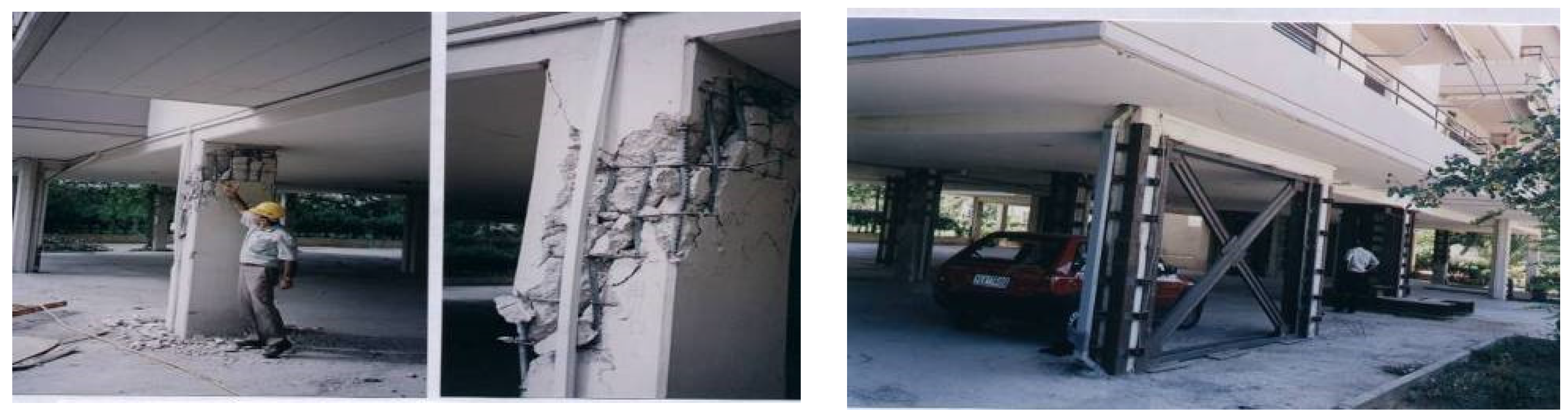
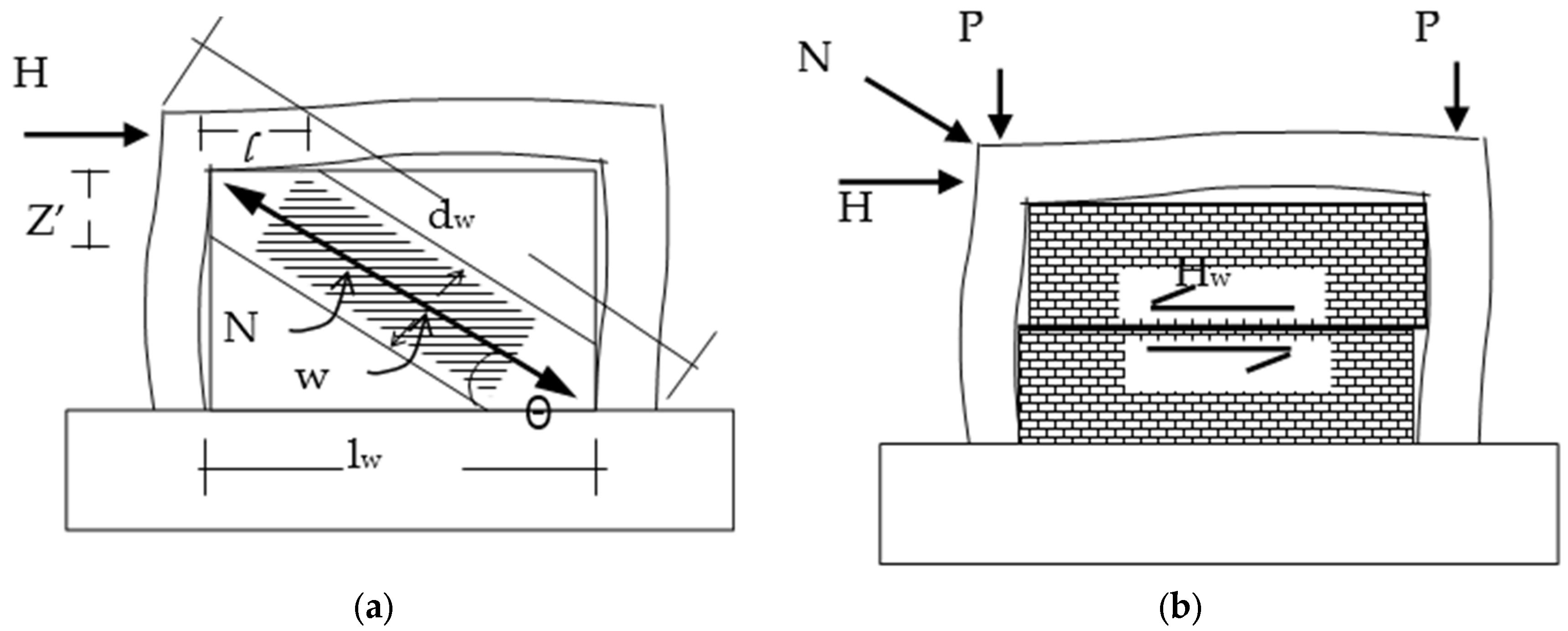
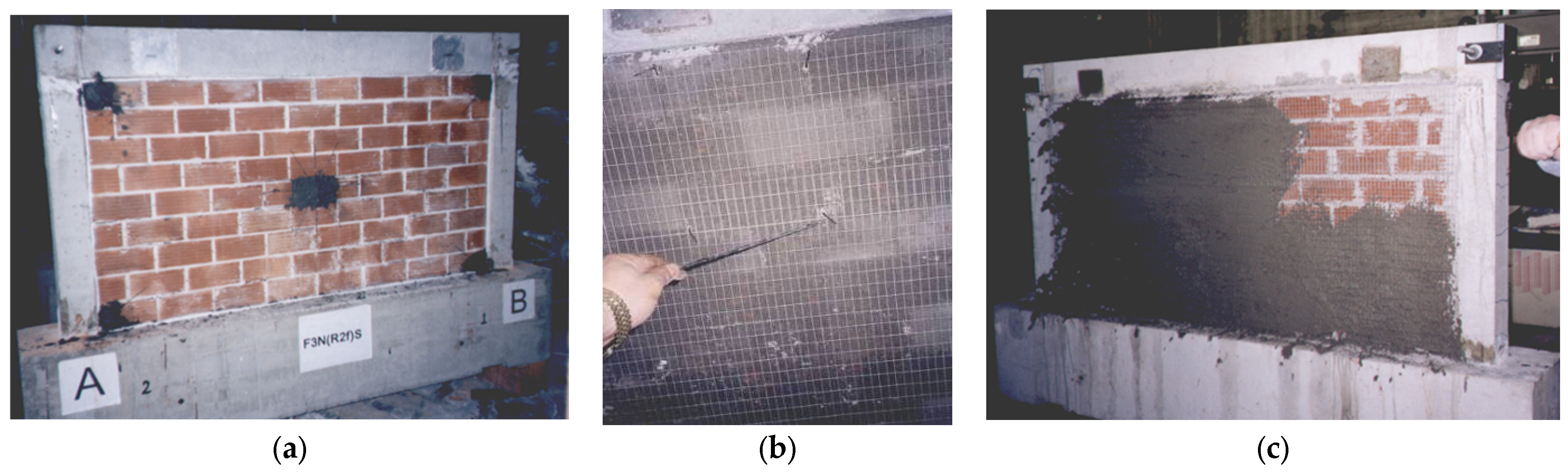
The deformability and strength of the peripheral mortar joint interface between the UMI and the surrounding frame can influence the results of the infill–frame interaction. A very stiff peripheral mortar joint results in the narrowing of the compressive contact region that may lead to the crushing of either the corners of the infill panel or/and the damage of the RC frame at the same regions. These undesirable consequences are more likely to occur when a nonflexible interface is combined with an UMI of large stiffness, as is the case when strong mortar facades are used as retrofitting without combining them with measures to protect the corners of either the infill or the surrounding frame from crushing (Figure 8d).
(c)
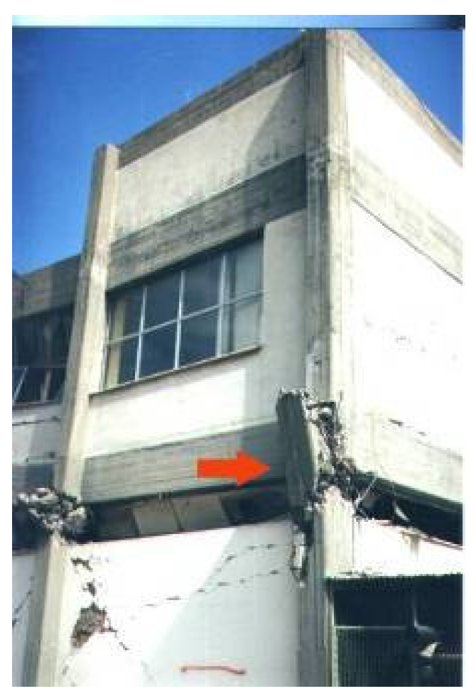
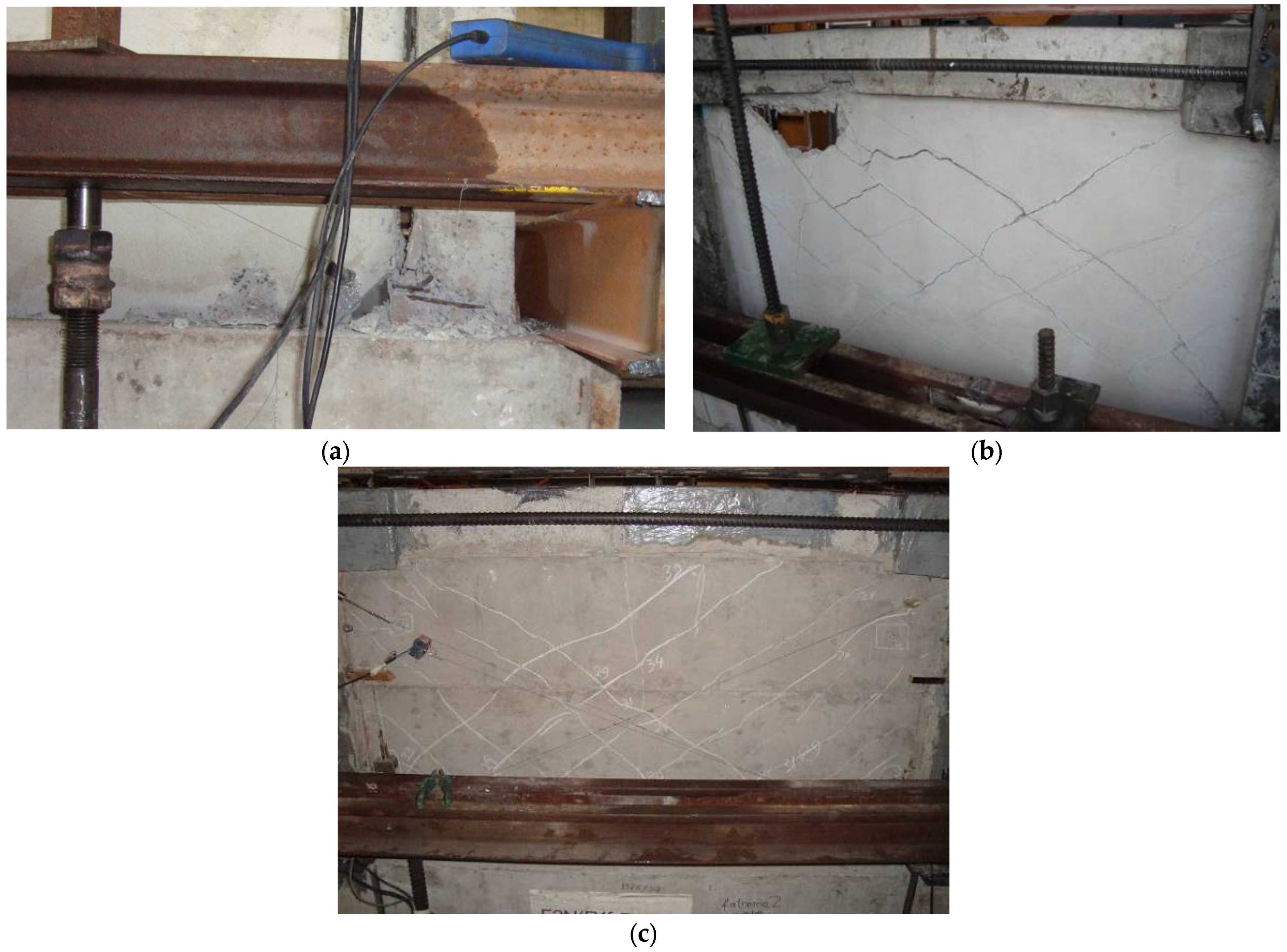
The premature failure of the UMI (Figure 8c) results in a sudden decrease of all the beneficial effects in the horizontal stiffness and load-bearing capacity. Moreover, the in-plane damage of the masonry infill may also facilitate its out-of-plane collapse because of the simultaneous out-of-plane seismic actions.
These important aspects of the interaction between unreinforced masonry infill and the surrounding frame, including the important effect of the peripheral mortar joint, were demonstrated by appropriate numerical simulations that include all these possible nonlinear mechanisms, using the full set of test results for validation [44].
From the previous discussion, the detrimental effects of the presence of UMI are: (a) the undesired forms of damage of underdesigned soft-story systems (Figure 1, Figure 2 and Figure 3); and (b) the unintentional formation of short columns (Figure 4). The response from both these undesired influences resulting from the presence of UMI could be well predicted, and the structural system could be thus protected by specific detailing during design or by retrofitting countermeasures, among which is the one studied in Section 3. Basic parameters are the mechanical properties of the masonry infill combined with those of the peripheral mortar joint at the interface between the masonry infill and the surrounding frame. A realistic numerical approximation of the seismic response of one-story, one-bay RC frame is the basis for approximating the seismic response of the multistory RC building including UMI [47,48]. The influence of door or window openings should also be included [49,50,51,52]. When the detrimental effects of UMI are prohibited, the interaction of UMI with surrounding framed structures can be beneficial because they represent a first line of defense, due to their added stiffness, strength, and energy consumption, against horizontal earthquake loads. The premature failure of UMIs during their in-plane (IP) seismic response represents a considerable repair cost. For strong earthquake excitations, the partial or total out-of-plane (OOP) collapse of UMI panels (Figure 9) is a serious hazard that is being currently investigated [53,54,55]. Such undesired OOP response interacts with the IP response interaction, being influenced by the boundary conditions and the progress of the damage for the UMI and the surrounding frame.

3. Cyclic Behaviour of a RC One-Bay, One-Story Frame Retrofitted with an RC Infill Panel

In this section, the impact of the studied particular retrofit consisting of constructing an RC infill within the bay of an existing RC frame is investigated [56,57,58,59,60,61,62,63,64,65,66] as a countermeasure of the presence of the soft story. This is done through an experimental study employing 1/3 scaled single-story, one-bay RC frames, described in Section 3.1., in order to identify significant nonlinear mechanisms from the interaction of the RC infills with the surrounding frame and to quantify the result of such a retrofit on stiffness, strength, ductility, and energy consumption. This retrofitting scheme is usually combined with the jacketing of the columns or beams of the surrounding frame. Choi et al. [57] conducted a series of experiments employing one-bay, single-story scaled RC frames having RC-IP, which were connected by using various structural details to the surrounding frame. They concluded that the addition of an RC infill wall significantly reduced the drift and improved the stiffness and the ultimate strength. Moreover, they observed that the failure mode of the RC infill walls was dominated by a shear compression effect. Anil and Altin [58] and Altin, Anil, and Kara [59] conducted a series of experiments with 1/3 scaled one-bay RC frames, of either one or two stories, including RC infills in various forms that replicated door and window openings. They concluded that such infills increased substantially the stiffness, strength, and energy dissipation of these frames with RC infills when compared with the corresponding bare frames. They also performed analytical studies and predicted quite successfully the strength of these RC infilled frames. Manos [60] and Manos et al. [61,62] investigated the behaviour of RC infilled frames located at the ground floor of buildings subjected to cyclic seismic-type loads. These RC infills were either not connected or connected with the surrounding frame being retrofitted with RC jackets. This manuscript is a summary of the findings of this investigation. Biskinis et al. [63] proposed calculation models for the yield moment, the secant-to-yield-point-stiffness, the cyclic ultimate chord rotation, and the shear resistance (due to diagonal tension, shear sliding, squat-wall effects, etc.) of the composite wall produced by infilling the space between two RC columns with RC panels without encapsulating them. They validated this methodology by comparing their predictions with experimental measurements. Moreti et al. [64] and Papatheocharis et al. [65] employed the diagonal strut model, broadly used as a design tool in the case of masonry-infilled RC frames, for the design of reinforced concrete (RC)-infilled frames. They conducted an extensive literature review and an experimental investigation to support this study, concluding that for the best performance of an RC-infilled frame with non-ductile members, the columns should be strengthened with RC jackets concurrently with the casting of the RC infill. Furthermore, the RC infill should be connected to the frame through dowels, preferably only along the horizontal interfaces with the frame, in order to avoid early failure in the columns. They also concluded that the failure of RC-infilled frames with non-ductile reinforcement detailing is likely to occur in a frame component and not in the infill. Chrysostomou et al. [66] employed the pseudo-dynamic method to test a full-scale 3-D RC four-story building, having the central bay of two opposite three-bay frames retrofitted with RC infills. They used different connection details between the RC infill and the surrounding frame as well as reinforcement percentages for the two infilled frames. They concluded that this is a viable method for retrofitting and can be used to strengthen existing ductility and strength-deficient structures. The current research was initiated by the relevant provisions of the design guidelines (OASP 2012 [67], which cover a wide range of a number of distinct design choices for a retrofitting technique denoted as reinforced concrete infill panel (RC-IP). These choices are: (a) an RC-IP without any connections to the surrounding frame; (b) an RC-IP with light connections to the surrounding frame; and (c) casting an RC-IP with structural details connecting it with the surrounding frame. This represents the construction of a new shear wall extending to the whole building height. The construction of (a) and (b) are limited to the soft story of multi-story buildings with open ground floor parking space where such a retrofitting scheme can be easily applied. The construction of a new shear wall extending to the whole building height is a very effective retrofit in increasing the stiffness, strength, and ductility for an underdesigned RC multistory building [10]. However, such a construction can be a complex, costly, and time-consuming operation for an existing building because it involves a large number of structural interventions and alterations to the functioning spaces at many levels; it also requires strengthening of the foundation for the new shear walls, which represents an additional complex and costly operation. The retrofitting scheme which is studied here is aimed as a structural intervention at the soft story in the following two alternatives:
  • The RC-IP is not structurally connected to the surrounding R/C structural elements (columns or beams). Alternatively, a limited connection between the RC-IP and the upper/lower horizontal frame interface is constructed.
  • The RC-IP is constructed together with steel ties connecting the RC-IP with the surrounding RC structural elements strengthened by jacketing within the bay of a frame (columns or beam). The thickness of this RC-IP is usually smaller than the width of the beams and columns that form the infilled bay of the frame.
For this purpose, the one third (1/3) one-bay, single-story scaled RC specimen is used with all information of its geometry, mechanical characteristics of all the materials and structural detailing defined by testing, as shown in Figure 7, Figure 8 and Table 1. This specimen is step-wise transformed to: (a) a retrofitted frame with RC jackets (Figure 10); (b) a 50-mm-thick unreinforced concrete infill panel (UC-IP) connected to the same retrofitted frame with steel anchors. (Figure 11); and (c) the same as before but having a lightly reinforced RC-IP (Figure 11). Prior to applying the horizontal cyclic load, each specimen was subjected to a vertical load in a way that each one of its columns was loaded with an axial load of 50 KN that was kept constant throughout the horizontal loading sequence. Together with this vertical load, an in-plane horizontal cyclic load was applied at the top bay of the frame of continuously increasing amplitude (Figure 10 and Figure 11). This experimental setup approximates in a realistic way the stress field of such a prototype subassembly subjected to in-plane seismic actions. The measured response is detailed in Section 3.1, and it subsequently utilized to compare it with corresponding numerical predictions, thus validating a specific numerical analysis process (Section 4). There are five specimens in total. Two specimens are RC frames without RC infills (Bare 1 and Bare jacket1,2) and three RC frames are the previous RC frames hosting either UC or RC infills (UC-IP 1, UC-IP 2, RC-IP 3), which are described in detail in this Section 3.1.

3.1. Unit T-Beams with Open Hoop CFRP Strips Employing Specific Mechanical Anchoring Devices

-
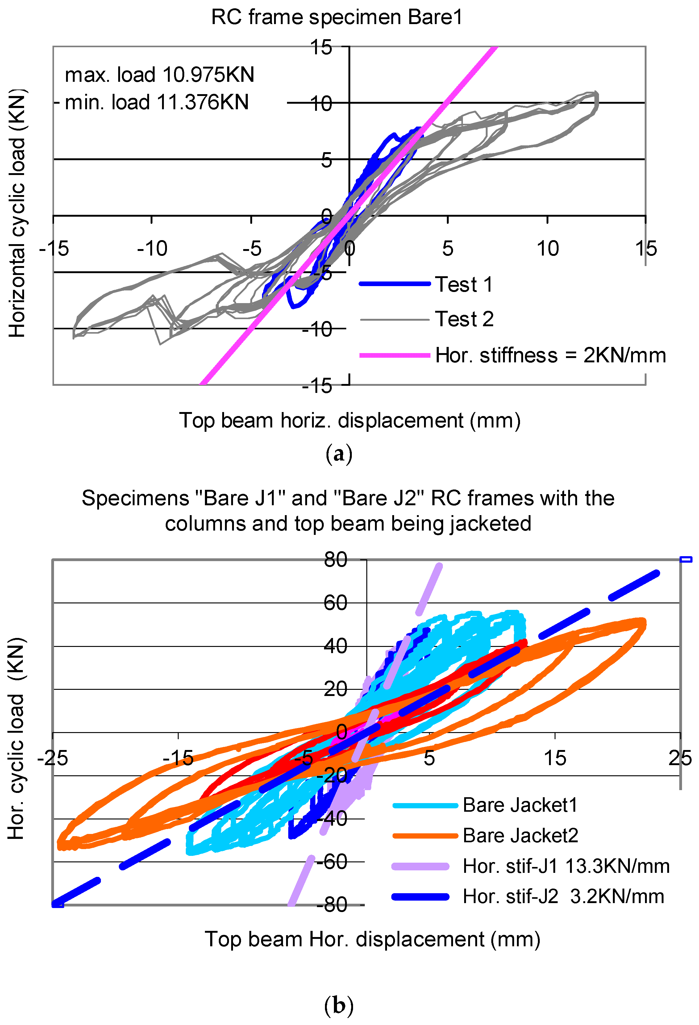
Bare 1. This is an RC frame specimen without any jacketing of its columns and top beam with the code name Bare 1. The same is true of the one depicted in Figure 6 for the masonry infill study. The basic mechanical properties of the materials employed in their construction are listed in Table 1. The obtained cyclic response is depicted in Figure 12a.
-
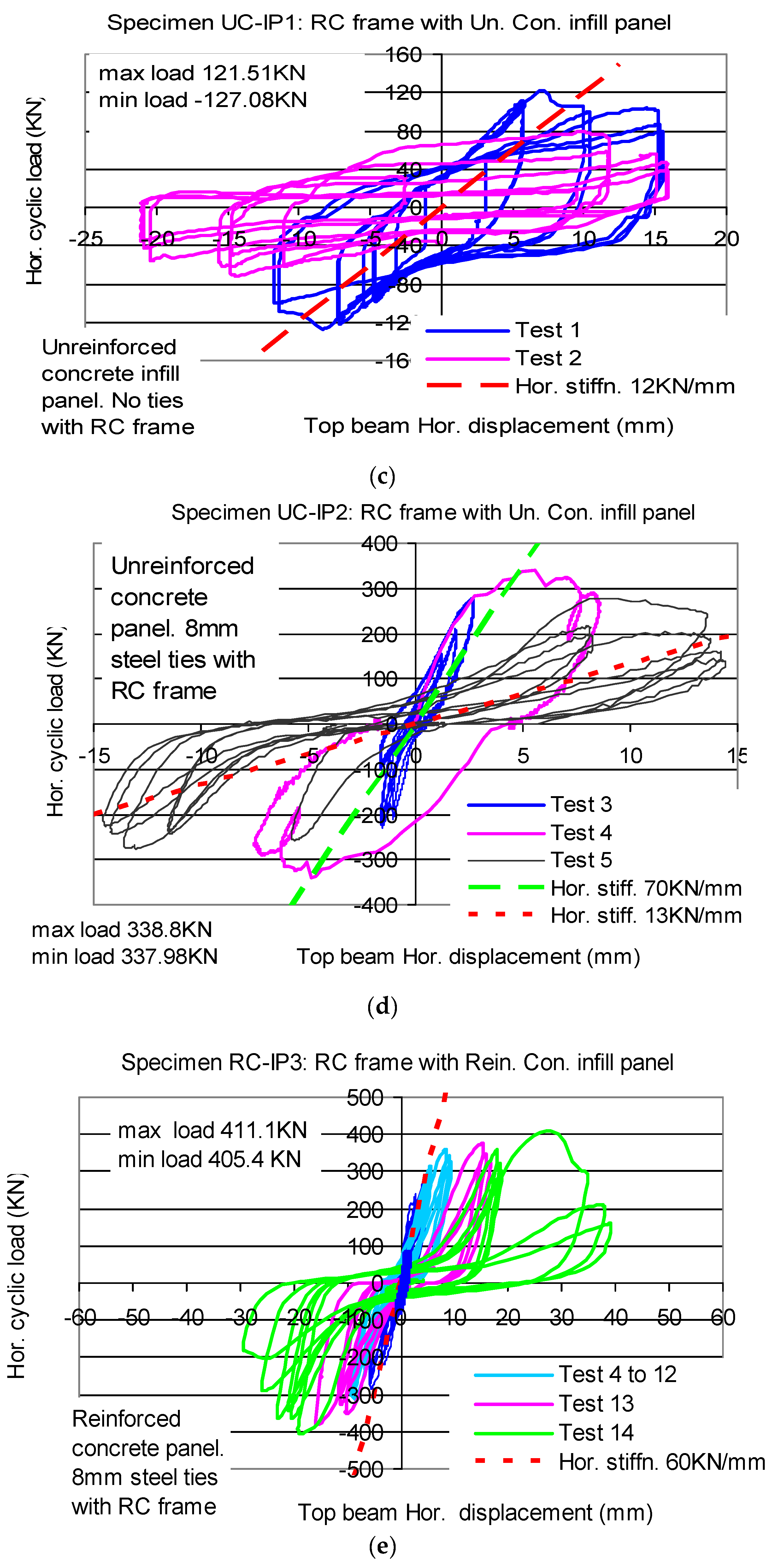
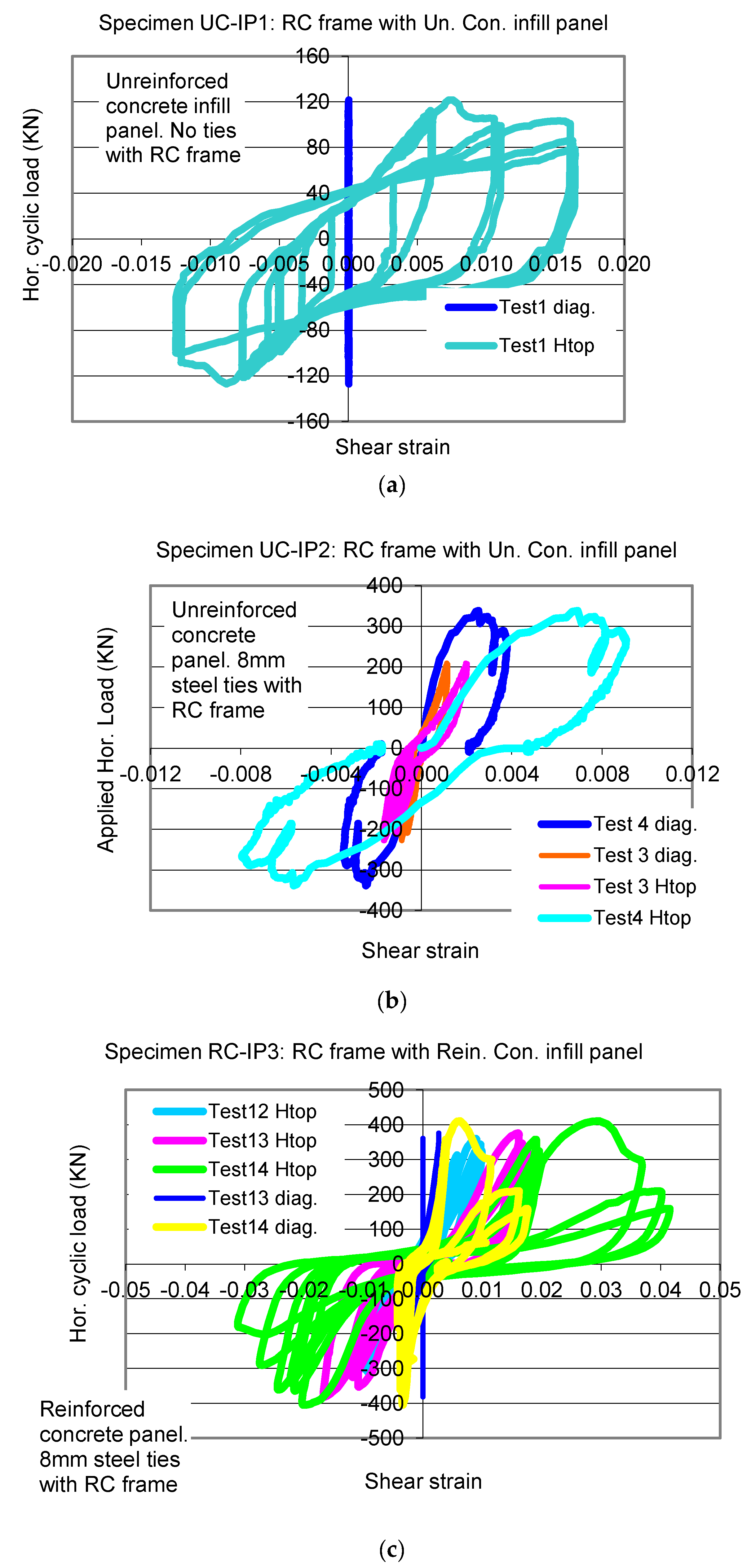
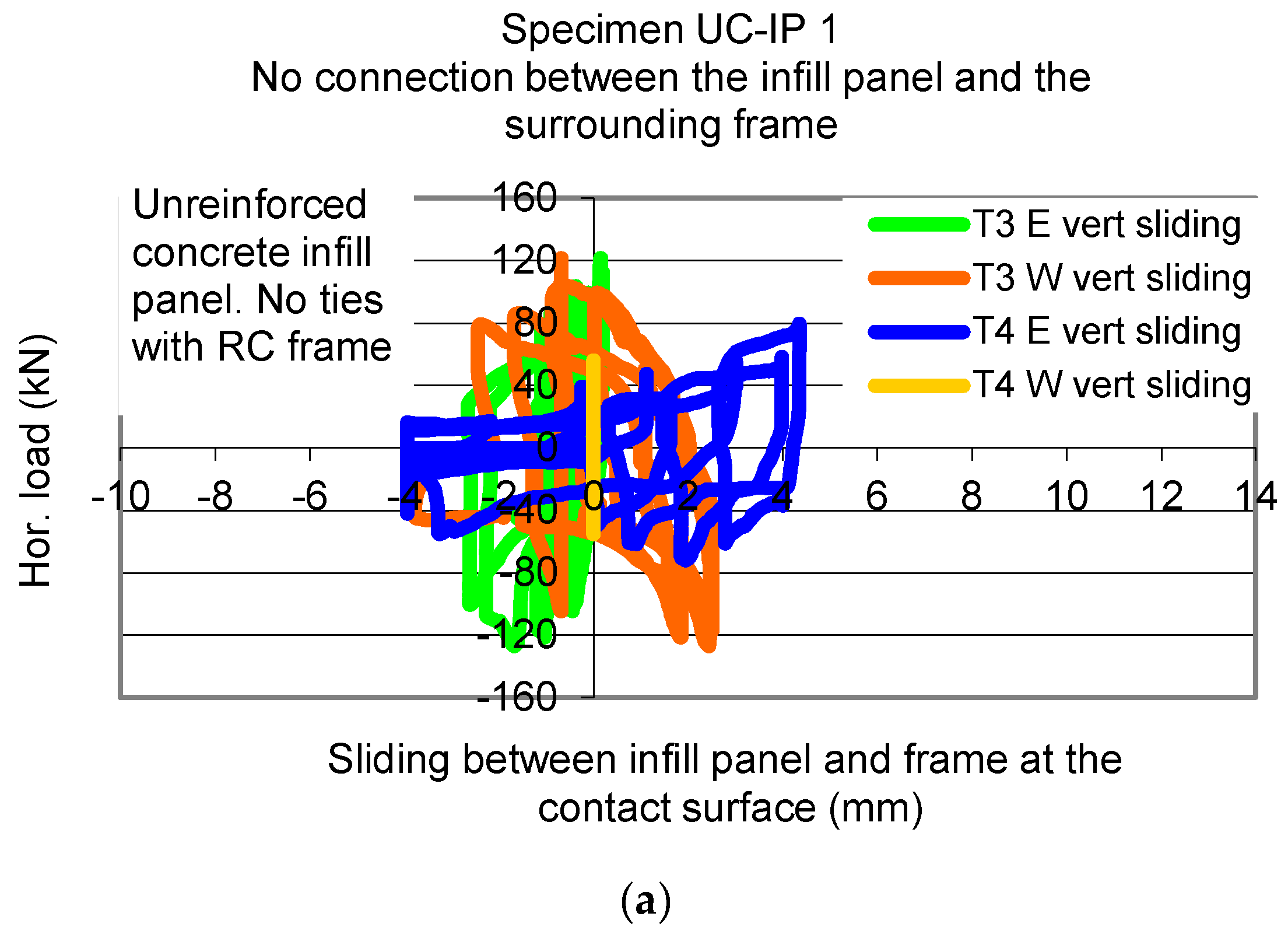
Unreinforced Concrete–Infill Panel 1. This specimen was formed by filling the bay of specimen Bare 1 with an unreinforced concrete panel having a thickness of 50 mm with concrete compressive strength equal to 22 MPa. This concrete panel was simply cast within the bay without the use of any ties between this concrete panel and the structural members of the surrounding frame. The code name for this specimen is UC-IP 1. Its cyclic response is depicted in Figure 12c.
-
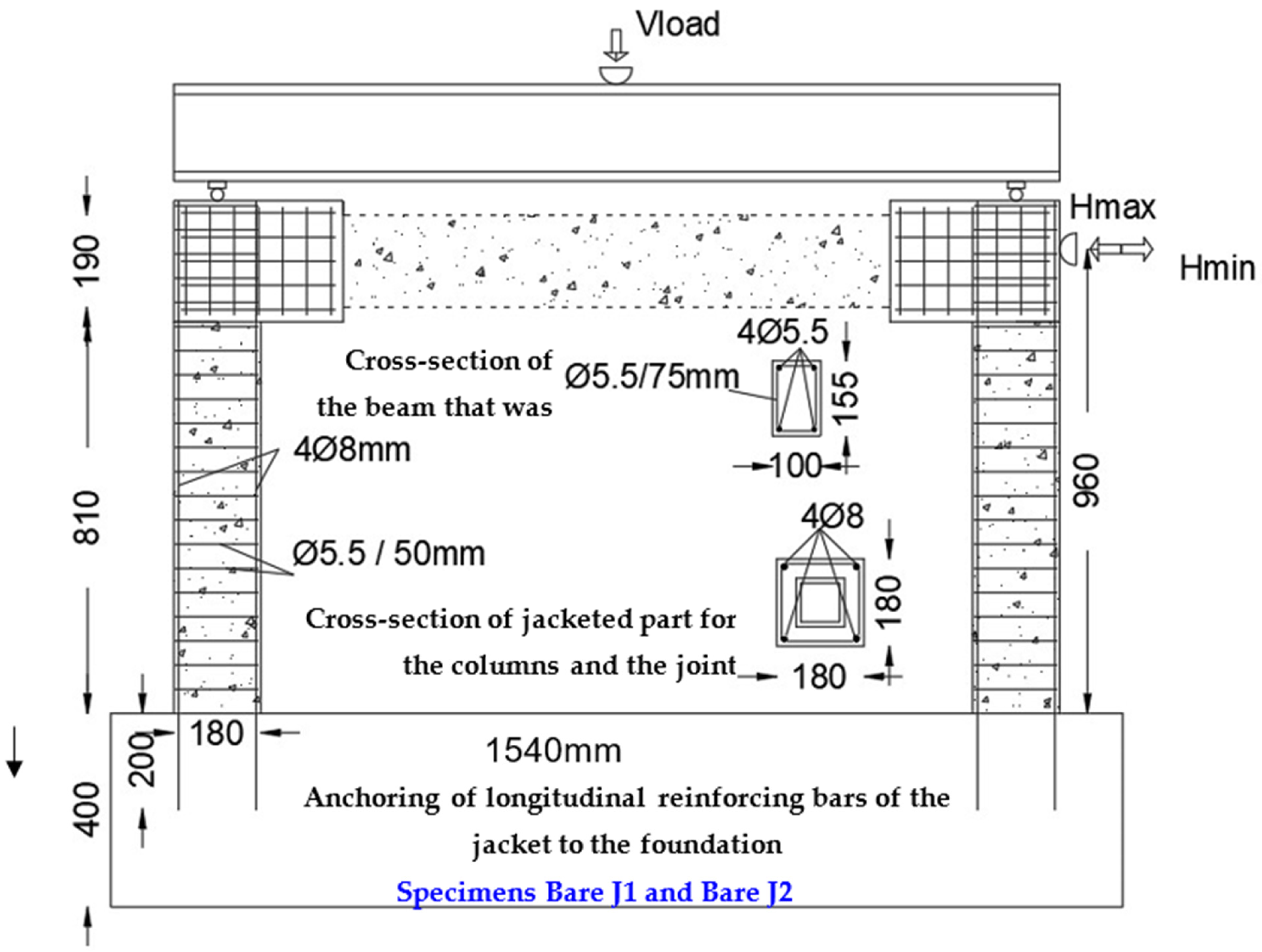
Bare Jacket1. This specimen (Figure 10) was formed by removing the fractured unreinforced concrete panel of specimen UC-IP 1 and by retrofitting the columns and part of the beam of the RC frame near the beam-to-column joints with concrete jackets. The cross-section of the jacket was 180 mm by 180 mm, having at each of its four corners longitudinal steel reinforcing bars of 8 mm diameter and 570 MPa yield stress (Figure 10). These jackets were also reinforced with closed hoop steel stirrups of 5.5 mm diameter spaced at 50-mm intervals. These jackets were cast with high-strength concrete having a compressive stress of 40 MPa. The code for this specimen is Bare jacket1. The obtained cyclic response for this retrofitted frame is depicted in Figure 12b.
-
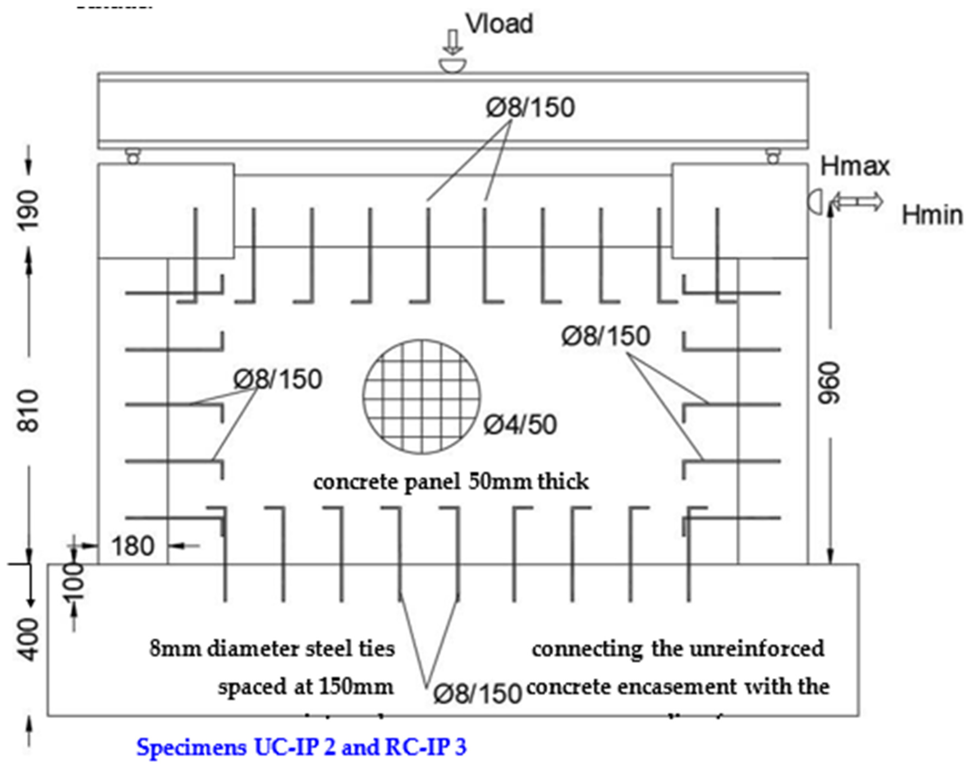
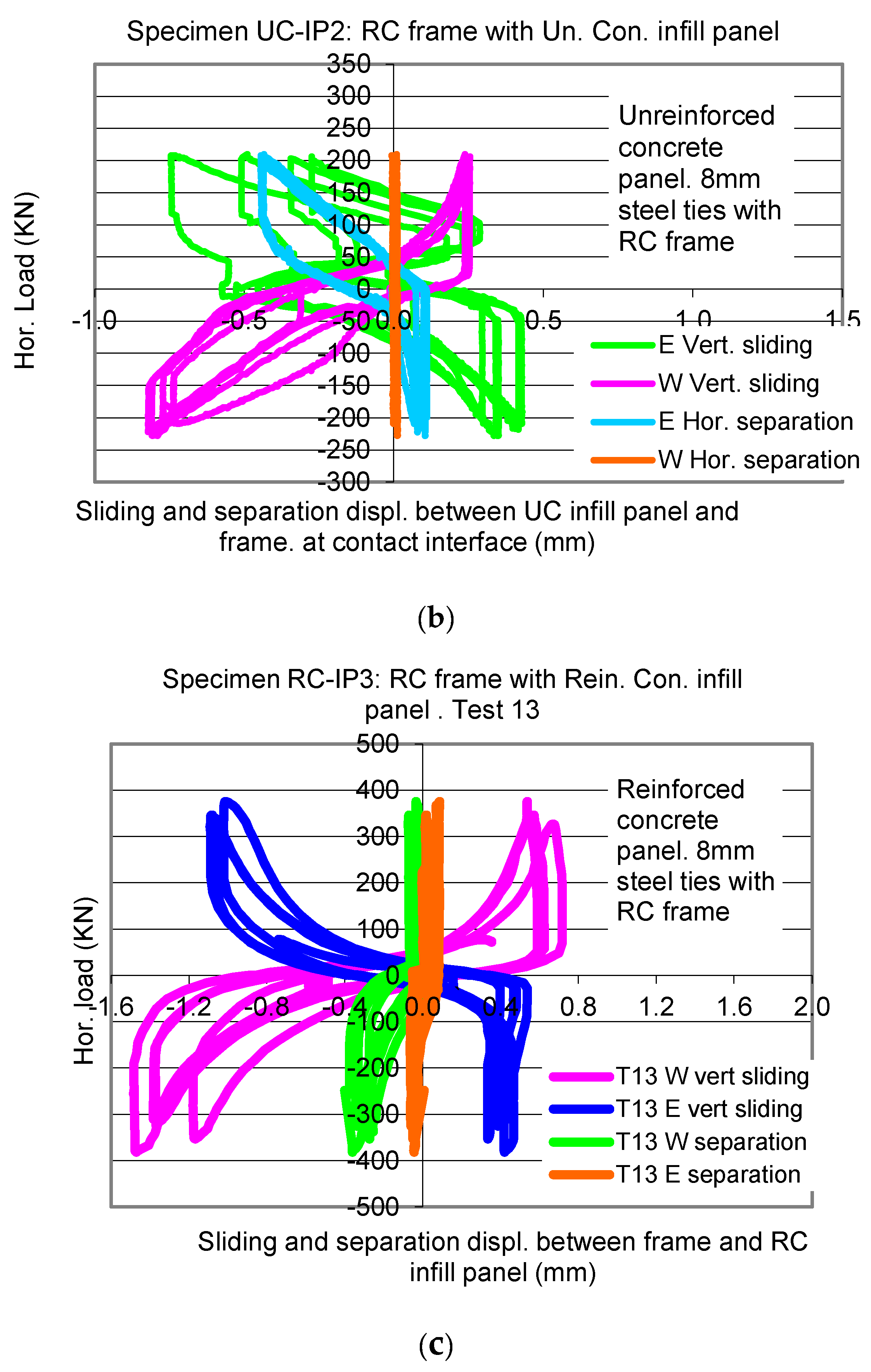
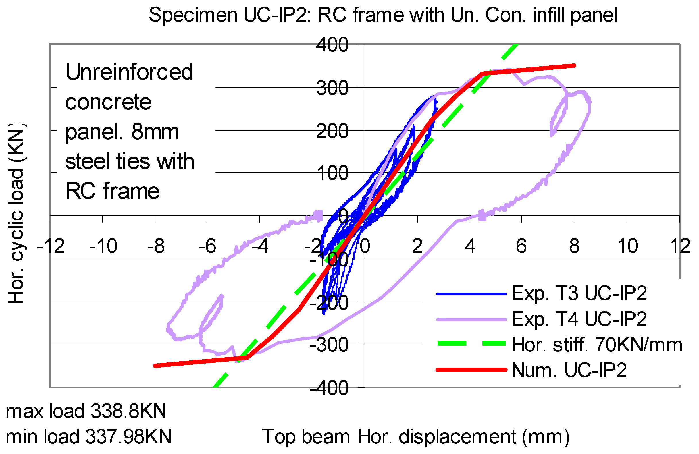
Unreinforced Concrete-Infill Panel 2. This specimen was formed by filling the bay of specimen Bare J1 with an unreinforced concrete panel having a thickness of 50 mm with the concrete compressive strength equal to 22 MPa. This time the unreinforced concrete panel was cast within the bay by using 8-mm-diameter steel ties, with a yield stress equal to 570 MPa, spaced at 150 mm intervals connecting this panel and the structural members of the surrounding frame, as shown in Figure 11. These ties were anchored at the concrete columns and beam, before casting the unreinforced concrete infill, by drilling holes and using a special resin to ensure bonding. The code name for this specimen is UC-IP 2. The obtained cyclic response for this sample is depicted in Figure 12d.
-
Bare Jacket2. This specimen resulted from removing the fracture unreinforced concrete panel of the previous specimen, UC-IP 2. It is almost the same as the previous retrofitted frame specimen Bare jacket1, having been subjected to a loading sequence as part of the previous specimen UC-IP 2. The code name for this specimen is Bare jacket2. Its cyclic response is depicted in Figure 12b, together with the corresponding response of Bare jacket1.
-
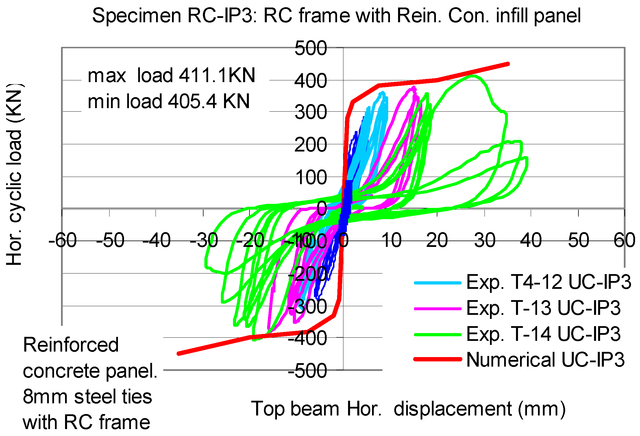
Reinforced Concrete–Infill Panel 3. This specimen (Figure 11) was formed by filling the bay of specimen Bare jacket2 by using the same steel ties as before for specimen UC-IP 2. The reinforcement of the concrete panel was a net of steel reinforcing bars of 4.5 mm diameter (500 Mpa nominal yield stress) spaced at 85-mm intervals in both horizontal and vertical directions. The code name for this specimen is RC-IP 3. Its cyclic response is depicted in Figure 12e.
Figure 12. (a) Horizontal displacement versus horizontal load cyclic response of specimen Bare-1. (b) Horizontal displacement versus hor. load for specimens Bare Jacket1 and Bare Jacket2. (c) Horizontal displacement versus horizontal load cyclic response of specimen UC-IP 1. (d) Horizontal displacement versus horizontal load cyclic response of specimen UC-IP 2. (e) Horizontal displacement versus horizontal load cyclic response of specimen RC-IP 3.
Applsci 12 11597 g012aApplsci 12 11597 g012b
All specimens were subjected to a number of imposed horizontal displacement cycles with a frequency of 0.1 Hz and with a continuously increasing amplitude within sequential loading groups, each group having three cycles of constant horizontal displacement amplitude.
Figure 13a–c depicts the observed damage of specimens UC-IP 1, UC-IP 2, and UC-IP 3, respectively. Summary results of the observed response are listed in Table 3. Column 2 in this table lists the observed initial horizontal stiffness, column 3 the measured maximum horizontal load, and column 4 the plastic energy accumulated from the beginning of loading until the test in which the maximum horizontal load was measured. Columns 5 and 6 in this table list the ratio of the measured maximum response of the tested specimen by the response of the corresponding Bare specimen.
-
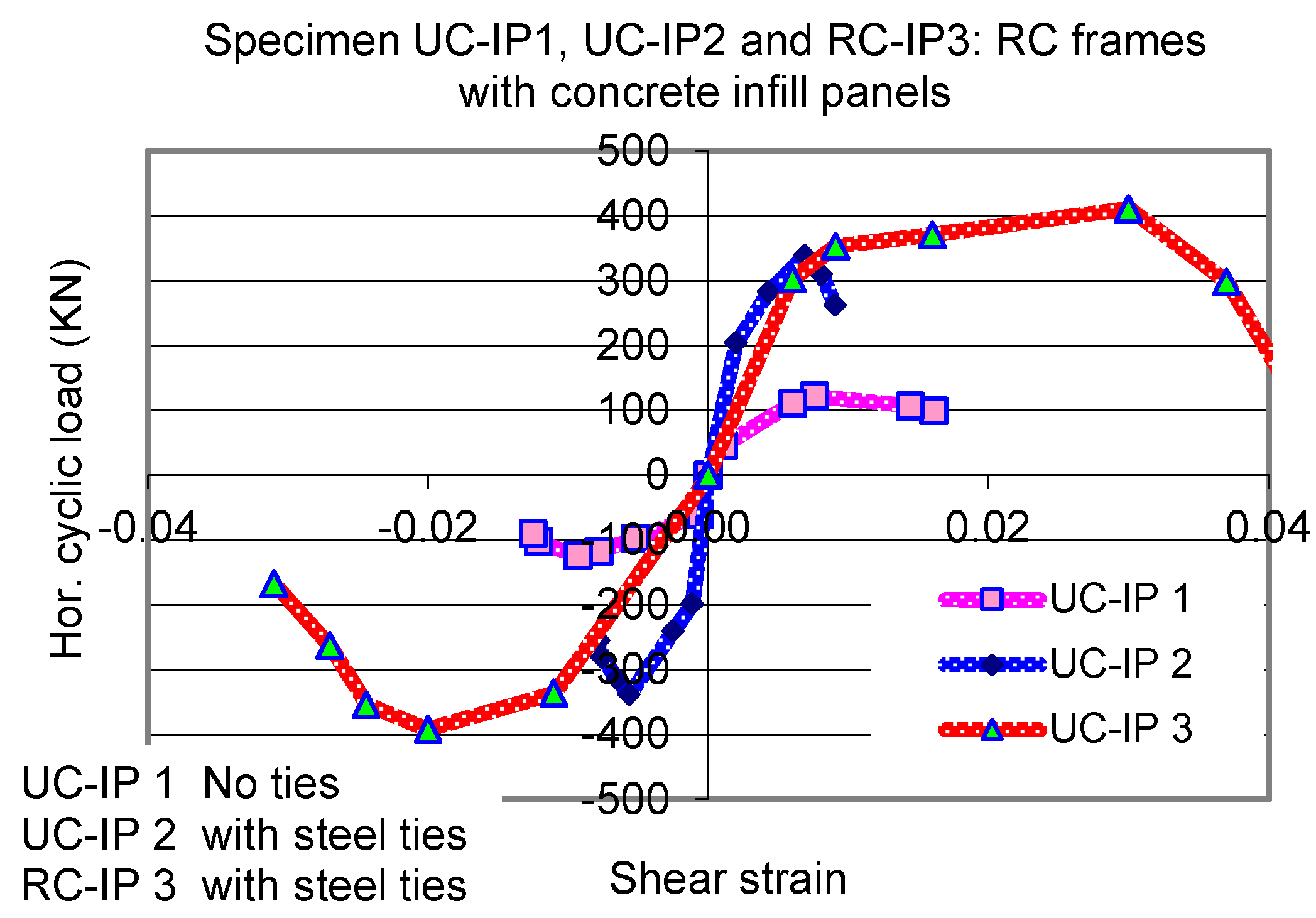
As expected, the construction of the concrete infill panel, with or without metal ties with the surrounding frame increases considerably the initial horizontal stiffness. The jacketing of the frame columns and part of the top beam also increase, to a lesser degree, this initial horizontal stiffness (Figure 12a,e and column 2 of Table 3).
-
The jacketing of the frame columns and part of the top beam increased almost five times the horizontal load-bearing capacity of the initial Bare frame. The Bare frame both before and after jacketing responded in a ductile manner reaching normalized interstory drift values in the range of 1.5% without a considerable decrease in the maximum horizontal load value. The inclusion of an infill panel increases even further, more than six times the horizontal load-bearing capacity of the jacketed frame (Figure 12a–e and column 3 of Table 3).
-
The jacketing of the frame columns and part of the top beam increased by more than five times the cumulative plastic energy until the maximum horizontal load was reached when compared with the corresponding cumulative plastic energy of the initial Bare frame. The inclusion of an infill panel increased even further this cumulative plastic energy (Figure 12a–e and column 5 of Table 3). This increase is quite spectacular for specimen RC-IP 3 and is due to the combination of the following contributing mechanisms First, the inclusion of the steel ties connecting the infill panel with the surrounding frame alters the interaction between frame and panel in such a way that the concentration of compressive stresses at narrow zones near the corners of the frame is avoided and neither the concrete panel nor the frame is crushed prematurely at these regions. However, when the infill panel is unreinforced (UC-IP2), it cannot sustain the large forces that develop due to its large stiffness, and it fails in a way depicted in Figure 13b. Instead, the capacity of the RC infill panel to large forces is substantially increased by the inclusion of the steel reinforcing net. Secondly, the development of cracking within the panel is controlled by the net reinforcement in such a way that it does not lead to a sudden decrease to its bearing capacity, even for much larger normalized interstory drift values reaching 2.5% (column 4 Table 3). This contributing mechanism mobilizes even further the steel ties connecting the panel with the frame, which represents an additional plastic energy accumulation medium. This combined effect for specimen RC-IP 3 explains the eleven times increase in cumulative plastic energy when compared to the jacketed frame (column 8 of Table 3), whereas the corresponding increase for the UR-IP 2 specimen is only twofold.
-
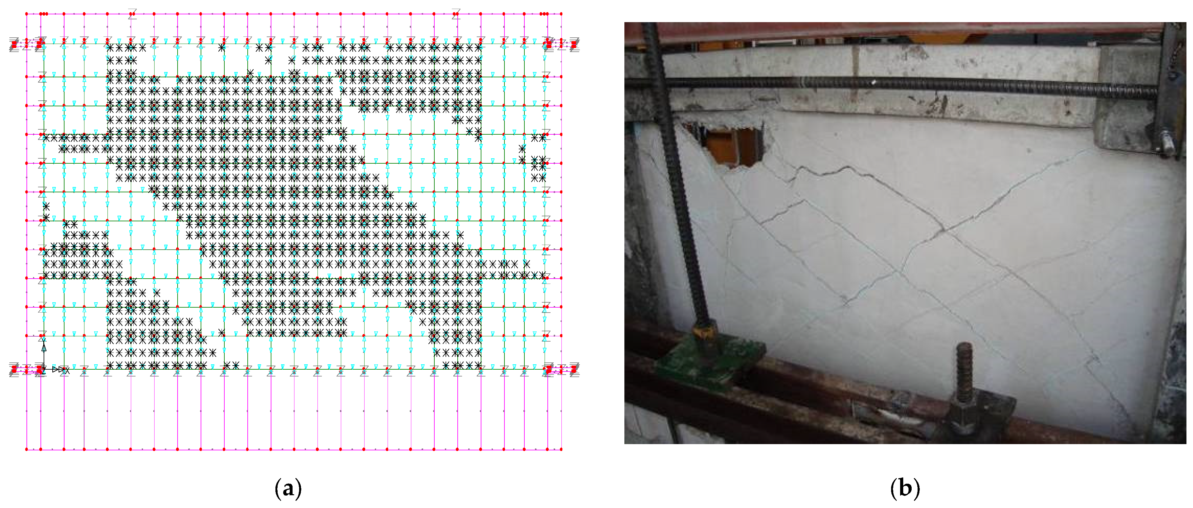
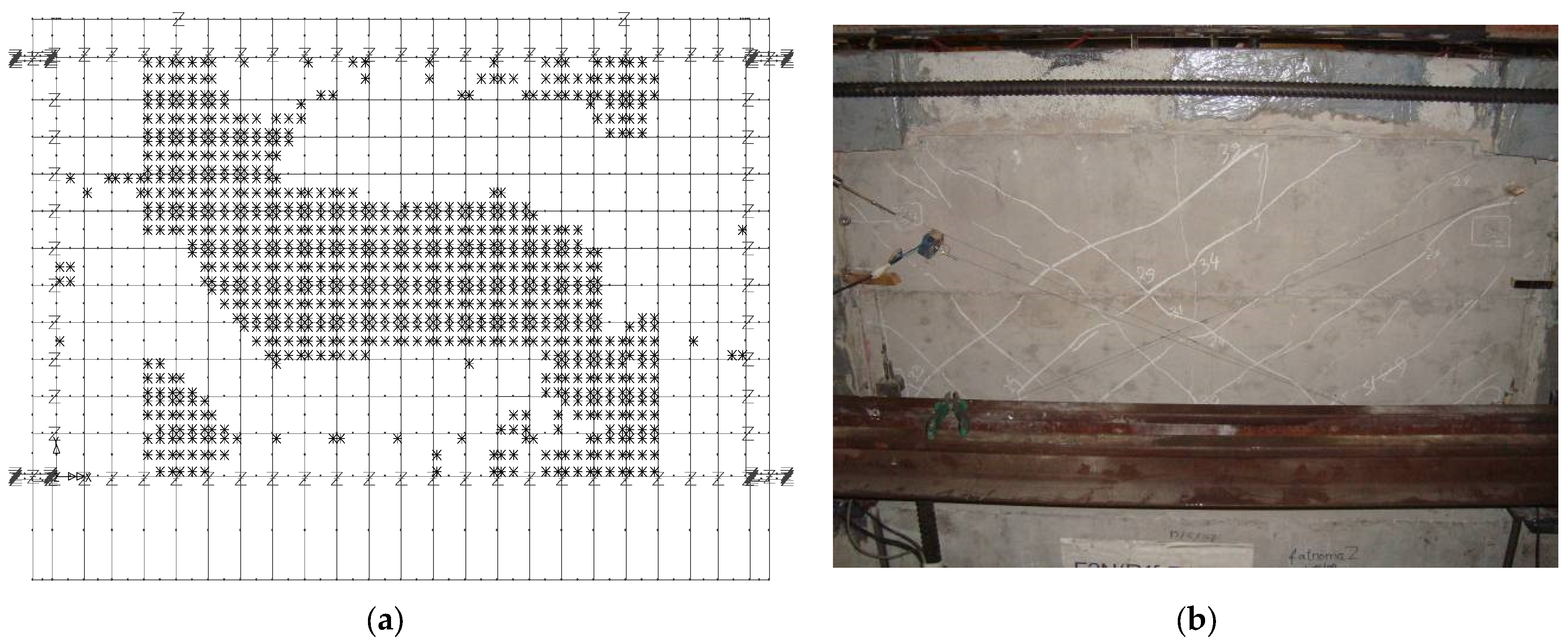
The fact that the RC infill panel sustains large horizontal forces and interacts successfully with the surrounding frame can also be seen by the level of shear strains which develop within the infill panel when the maximum horizontal load capacity is reached (Figure 14c).
-
All the above is expected to be valid for prototype structures. Constructing such an RC infill in a prototype frame bay needs proper design. The numerical simulation in Section 4 presents such a methodology.
Figure 14. (a) Shear strain response of UC-IP 1. (b) Shear strain response of UC-IP 2. (c) Shear strain response of UC-IP 3.
Applsci 12 11597 g014
In order to monitor the behaviour of the UC or RC infill panel itself, a number of displacement transducers were attached at both facades of this panel during testing measuring the variation of the length of its two main diagonals throughout the loading sequence. By combining these measurements, the average shear strain response of the concrete infill panel was obtained, and it is plotted in Figure 14a–c against the applied load (diag). For comparison purposes, an equivalent shear strain for the whole infilled frame is also plotted based on the measured horizontal displacement of the top beam of each tested specimen, which is identical to the drift value for this single-story frame (H-top). From Figure 14a, it can be deduced that for specimen UC-IP 1 the maximum applied load (127 kN) results in equivalent shear strain (drift) of approximately 1.5%. This is mainly due to the formation of the plastic hinges at the columns and beam and the separation of the infill panel from the surrounding frame, due to the absence of any ties, whereas the shear strain of the infill panel itself is almost zero. As already discussed, during this test the concrete of the infill panel was crashed locally at its four corners without the development of any diagonal tension cracking within the panel itself. This explains the zero shear strain in Figure 14a deduced from the instrumentation readings of the displacement transducers located within the infill panel away from the corners. It was underlined that this limit state is rather undesirable because this localized damage limits the horizontal load-bearing capacity of such a retrofitting scheme. This local damage at the corners of the RC infill may also inflict damage on the joints of the RC frame.
Figure 14c demonstrates that the presence of net reinforcement in the RC-IP3 leads this panel to sustain larger shear strain values within itself and for larger horizontal load (408 kN) than the case in which the infill panel was unreinforced (Figure 14b, UC-IP2, applied horizontal load 338 kN).
The displacement response in terms of sliding and separation between the infill panels and the two columns (E-East, and W-West) of the surrounding RC frame close to the region of the column-to-beam joints is also monitored. This response versus the applied load is depicted in Figure 15a–c for specimens UC-IP1, UC-IP2, and RC-IP3, respectively. The absence of any steel ties results in large sliding and separation displacement response at this interface (Figure 15a). The presence of steel ties (Figure 11) combined with a reinforced concrete infill panel (RC-IP3, Figure 15c) results in small separation displacement response, while allowing for considerable sliding displacements for relatively large horizontal load values (408 kN). In this way, the steel ties contribute to the accumulation of plastic energy through dowel action, which is an additional beneficial effect toward seismic resistance. The effect of the presence of the steel is also seen for the unreinforced concrete specimen but to a lesser extent (UC-IP2, Figure 15b). The absence of met reinforcement leads to the premature failure of the unreinforced panel (Figure 13b).
In Figure 16, the top horizontal load versus the equivalent shear strain of the infilled frame is shown for all three tested specimens with concrete infill panels in the form of envelope curves. As can be seen in this figure (see also Table 3), the steel ties result in a substantial increase of the in-plane horizontal load-bearing capacity. However, the lack of reinforcement of the infill concrete panel in this case results in its premature failure limiting this specimen in sustaining this load-bearing capacity for relatively low equivalent shear strain values (0.8%); this limitation is resolved by providing the infilled concrete panel with partial reinforcement. In this case (RC-IP 3), the maximum horizontal load-bearing capacity attains an even higher value (408 kN) than for UC-IP 2 (338 kN); moreover, this horizontal load-bearing capacity is sustained for equivalent strain (drift) values of nearly 4%. The specific limitations of the UC-IP 1, in terms of both load-bearing capacity and deformability, have been noted.

4. Numerical Simulation of the RC Frame—Infill Concrete Panel Interaction

Summary results of a numerical simulation are presented, predicting the behaviour experimentally studied in Section 3 infilled RC frames. In this numerical simulation, the same methodology presented in detail by Manos and Soulis [44] is followed employing commercial software [68,69]. The following important mechanisms were included in this simulation [44,60,61,62].
(a)
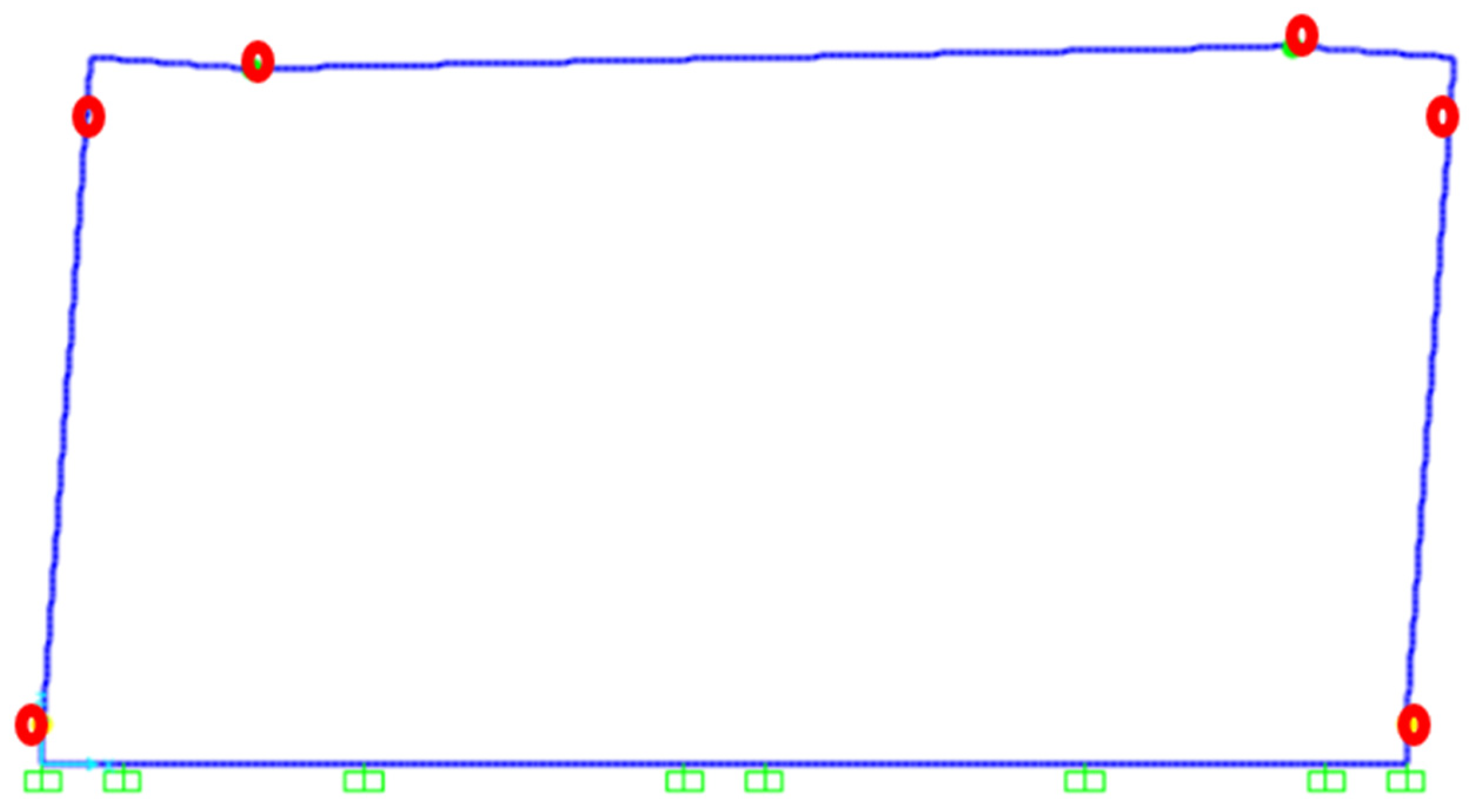
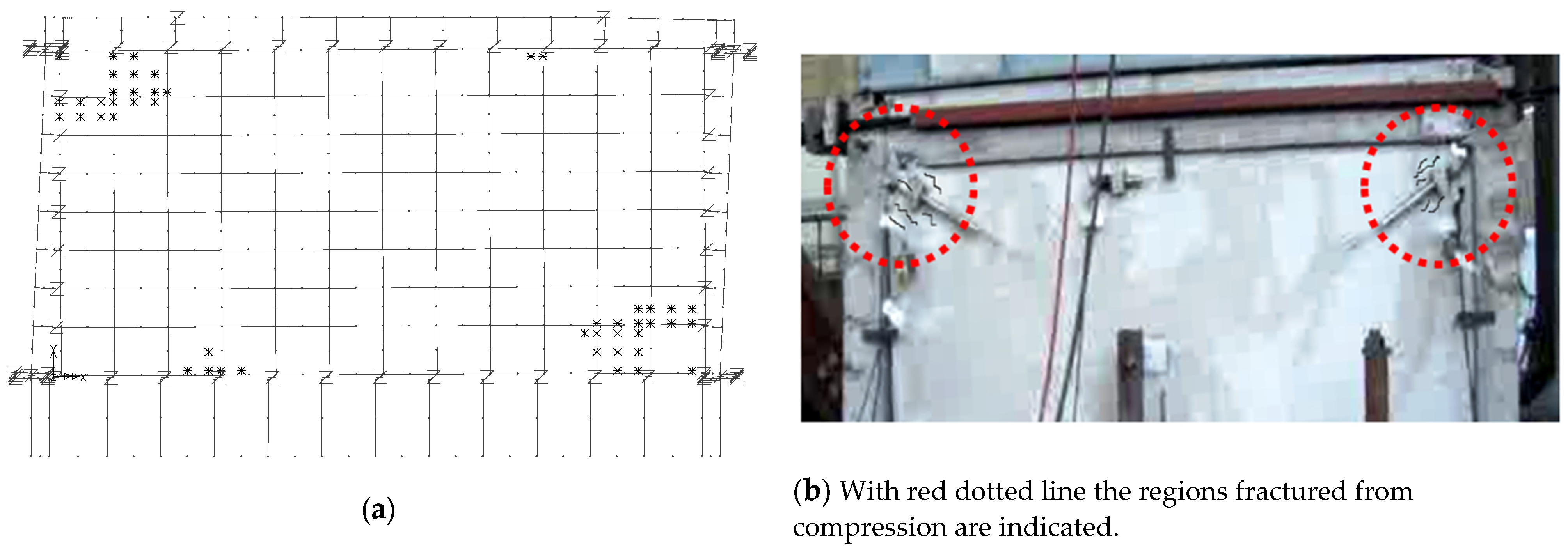
The possibility of either the two columns or the beam of the RC frame to form plastic hinges at their ends. To this end, the surrounding frame is simulated with linear frame elements based on the relevant cross-sections detailing specific locations for plastic hinges with nonlinear properties (bending moment against rotation) obtained from the cross-sectional reinforcing details and the mechanical properties of the concrete and the longitudinal reinforcement (Figure 6, Figure 10 and Table 1). This was done by employing an in-house-developed software based on the work by Mahin and Bertero [70] and the RC detailing [71]. Next, use was made of a number of commercial software packages that could simulate numerically the non-linear mechanism of the frame depicted in Figure 17 for specimen Bare jacket1 [60,61,62]. These commercial packages were employed in a combined way during the various stages of the numerical investigation [68,69].
In these numerical analyses, in order to trace the nonlinear solution path, a combined incremental/Newton–Raphson equilibrium iterative procedure included in these commercial packages has been utilized. The solution process follows a step-by-step incremental static material nonlinear analysis adopting initially a constant displacement increment. A line search technique was adopted together with a number of convergence parameters in an effort to improve the convergence rate and to achieve equilibrium from one step to the next. The resulting envelope curve in terms of a numerically predicted horizontal load against the top beam displacement is compared with the corresponding experimental cyclic response in Figure 18 demonstrating reasonable agreement.
(b)
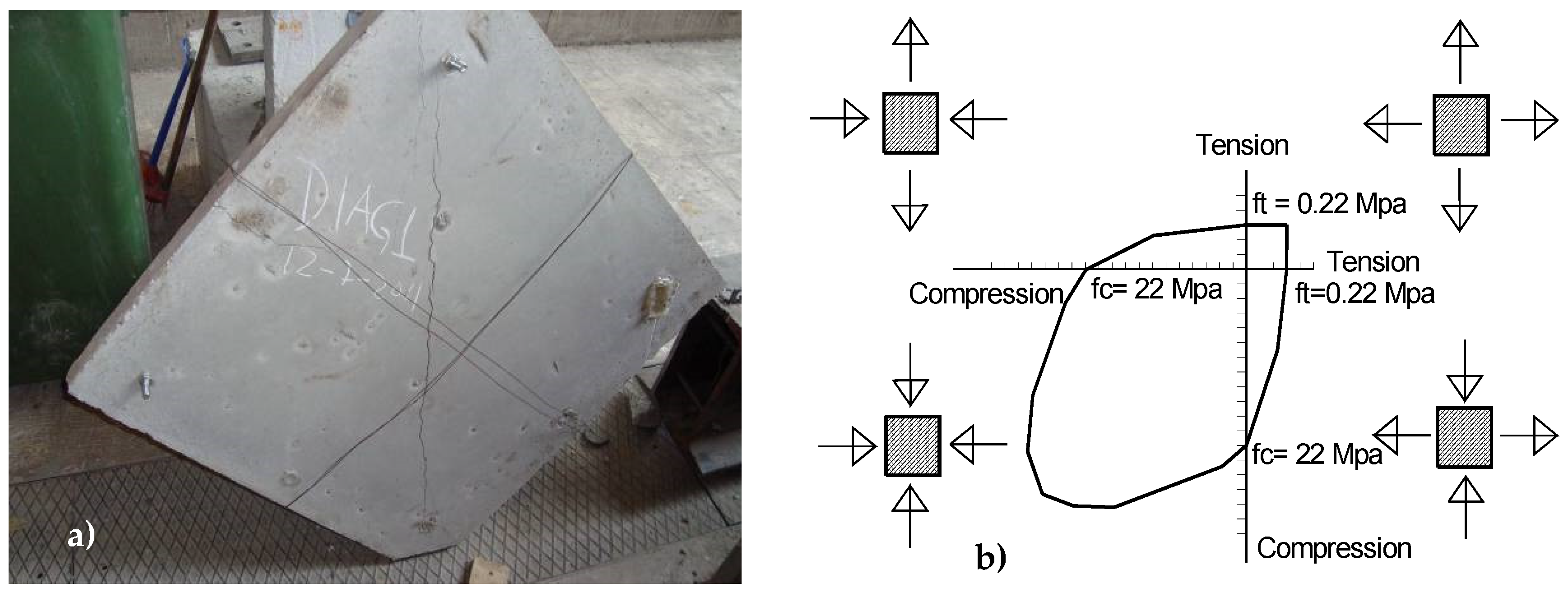
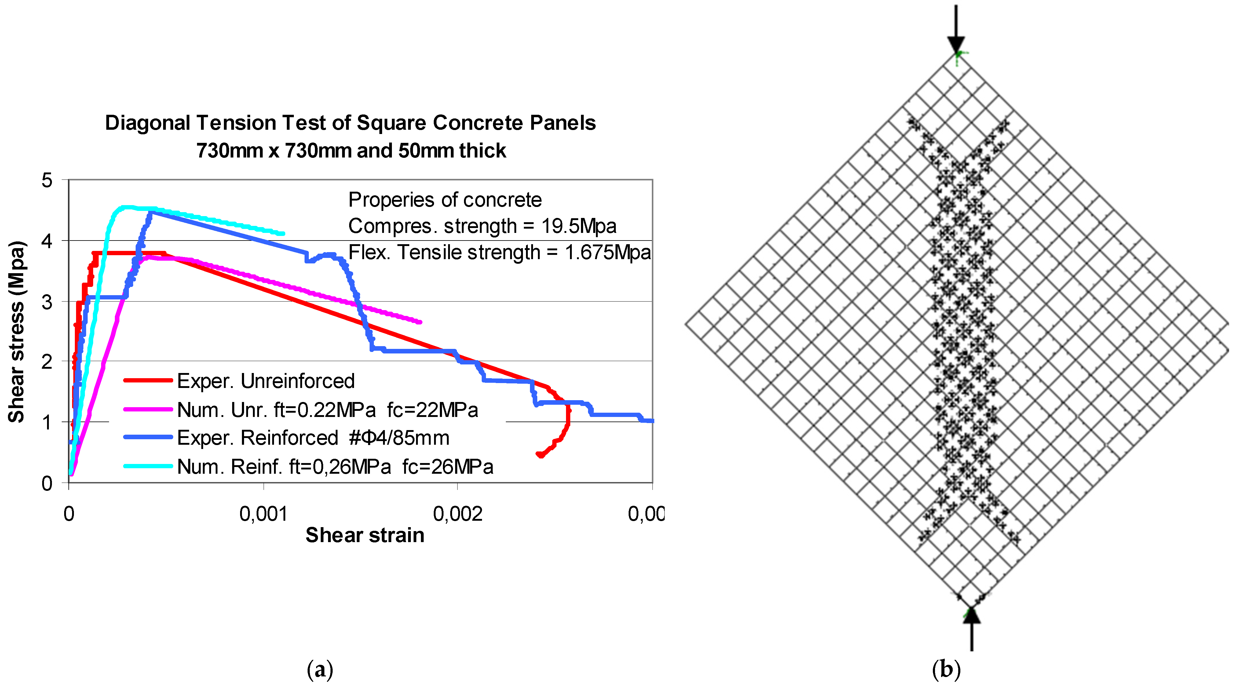
The same numerical simulation for the RC frame described before is also used here when forming the numerical model of the RC frame together with the UC-RC infill panels. The concrete infills were simulated with shell elements in all cases, together with a failure envelope for numerically predicting the formation of nonlinear limit states within the concrete infill (modified Von-Mises, Figure 19b) which was available in the used commercial software [68]. To quantify the parameters of this failure envelope, a number of square concrete panels with dimensions 730 mm × 730 mm and a thickness of 50 mm were constructed with the same concrete mix and at the same time with the concrete panels of the specimens presented in Section 3. These panels were next subjected to diagonal compression-tension (Figure 19a). Two of these diagonal compression panels were unreinforced (similar to UC-IP 1 and UC-IP 2) and the other two were reinforced with the same reinforcement as RC-IP 3 (see Figure 11). Figure 19a depicts the typical diagonal cracking, which developed along the main vertical diagonal during these tests [72,73,74,75]. This testing arrangement was numerically simulated by adopting the same failure envelope (Figure 19b) but with different sets of values—one set for the unreinforced panels and another set for the reinforced square panels. The values shown in Figure 19b for uniaxial compression or tension limits, equal to fc = 22 MPa and ft = 0.22 Mpa, correspond to the unreinforced panel. The corresponding values adopted for the reinforced panel are equal to fc = 26 Mpa and ft = 0.26 Mpa. These values were found from back analysis by utilizing these diagonal compression-tension tests (Figure 19a) and were employed for numerically simulating the behaviour of the RC infilled frames presented in Section 3.
As can be seen in Figure 20a, good agreement is reached between the numerical and measured diagonal compression–tension response through this nonlinear numerical simulation for these square panels tested in diagonal compression-tension. Based on this good agreement, the same numerical simulation is followed for the infilled RC frame specimens investigated in this study. This numerical simulation reproduced as a limit state the plastified region depicted in Figure 20b (where the “x” signs denote the areas reaching the adopted tensile limit state), which is along the same main vertical diagonal region depicted in Figure 19a.
(c)
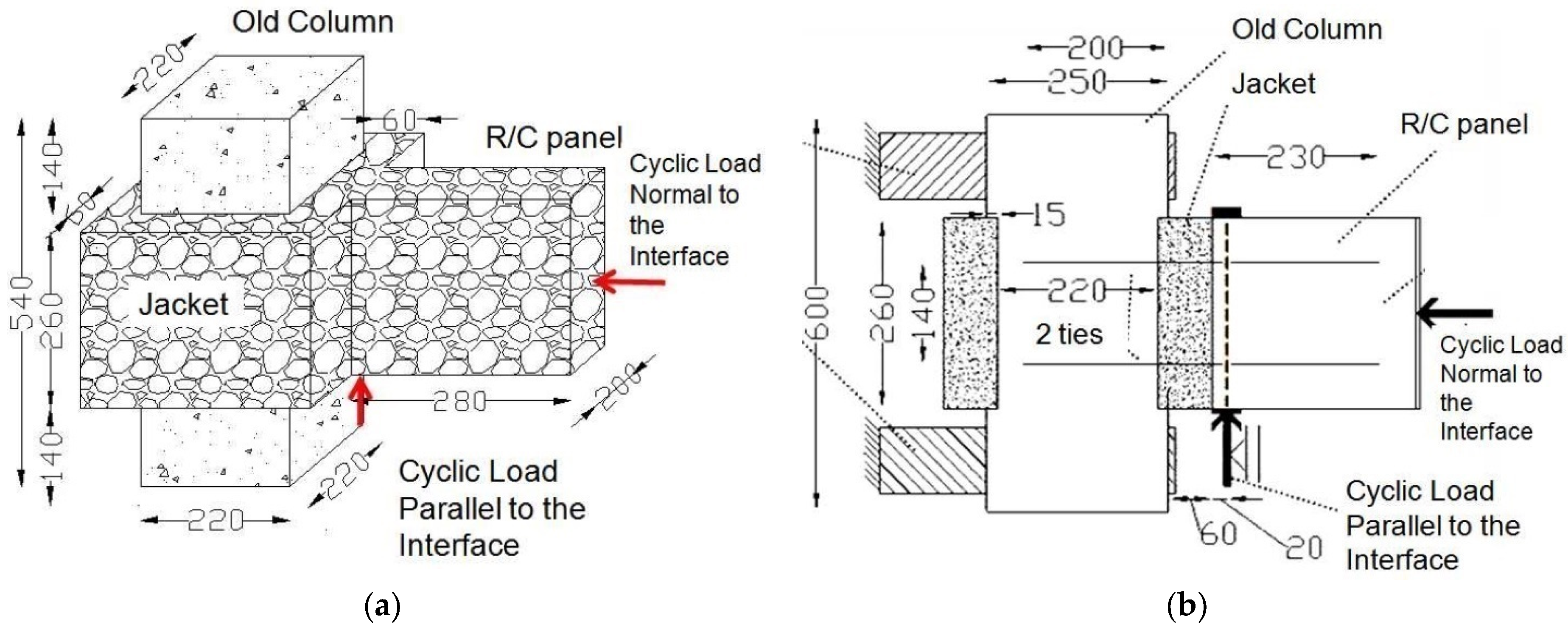
A first group of nonlinear link elements, which could not sustain any tension, was used to numerically simulate the possibility of the concrete infill to be separated from the surrounding frame. These elements could transfer shear at the interface when no separation was detected [44]. An additional second group of nonlinear link elements simulated the steel ties at their exact location, and they could transfer axial tensile and shear forces at the interface between the shell finite elements representing the infill panel and the linear finite elements simulating the surrounding frame. The nonlinear behaviour in axial tension of these link elements was derived from their diameter (8 mm) and yield stress (570 Mpa). These link elements were also provided with nonlinear properties to simulate the dowel action (shear force transfer) at this interface. A number of provisions with relevant empirical formulas are included in [67] that describe the nonlinear shear transfer mechanism between two concrete parts connected with a steel tie. In addition, an extensive experimental sequence was carried out at Aristotle University in an effort to quantify this shear force transfer for steel ties of diameters varying from 8 mm, identical to the ones depicted in Figure 11, up to 14 mm [60,61,62]. The used experimental setup is depicted in Figure 21 wherein a portion of a jacketed column together with a portion of the RC infill connected with these steel ties are subjected to combined loads indicated by the red arrows. All steel ties used in this experimental sequence as well, as for the specimens reported in Section 3, were embedded within the concrete volume in a way which prohibited any undesirable pullout.
Twenty-three specimens were built at the same time with the same geometry and the same quality concrete. Three of these specimens were built without any steel ties whereas the rest were provided with steel ties of the same steel grade having diameters varying of 8 mm, 10 mm, 12 mm, and 14 mm. Figure 21b depicts a cross-section of such specimens wherein the upper and lower parts of the “old” column are rigidly supported by the strong reaction frame. Initially, the load normal to the interface was applied as indicated in this figure, keeping its amplitude constant during one test. Then, a cyclic load with a direction parallel to the interface was applied with an eccentricity of 20 mm from this interface. The amplitude of this load was gradually increased until a limit state condition was reached. By comparing the nonlinear behaviour of the specimens with steel ties to that of the control specimen (without the steel ties), the non-linear shear force versus the relative sliding displacement at the interface due to the presence of the steel ties could be determined. This was used in the current numerical methodology to define the nonlinear constitutive behaviour of the second group of links in their tangential direction (parallel to the interface).
The obtained numerical response is presented in Figure 22, Figure 23, Figure 24, Figure 25, Figure 26 and Figure 27. The numerically predicted response of horizontal displacement versus load in the form of an envelope curve is compared against the corresponding cyclic measured response (Figure 22, Figure 24 and Figure 26). The results also include numerical predictions of regions that the numerical solution indicates damage (Figure 23a, Figure 25a and Figure 27a where the “x” signs denote the areas reaching the adopted tensile limit state). In Figure 23b, Figure 25b and Figure 27b is the corresponding observed damage.
Numerical Simulation of UC-IP 1: The previously described numerical methodology was first applied for specimen UC-IP 1. The numerical response in terms of envelope curve of the horizontal load versus the horizontal displacement at the top beam is depicted in Figure 22, being compared with the corresponding measured experimental cyclic response. The predicted peak load horizontal value is equal to 135 kN and compares reasonably well with the peak measured value equal to 127 kN. The predicted shear strain versus horizontal load response distribution compares reasonably well with the corresponding measured response. The numerically predicted compressive limit state at the corners of the infill panel (Figure 23a) also compares well with the crushing of the corners, which was observed for this specimen during testing (Figure 23b).
Numerical Simulation of UC-IP 2: The numerical response for specimen UC-IP 2, in terms of envelope curve of the horizontal load versus the horizontal displacement at the top beam, is depicted in Figure 24. This numerical response is compared with the corresponding experimentally measured cyclic response. The predicted peak horizontal load value is equal to 350 kN and compares reasonably well with the corresponding measured value equal to 338 kN. The predicted shear strain versus horizontal load response distribution compares reasonably well with the corresponding measured response. The observed sudden drop of the bearing capacity for specimen UC-IP 2 is not predicted by this numerical simulation. Figure 25a shows the diagonal tensile limit state numerically predicted at a wide region of this unreinforced infilled panel. This numerical limit state compares reasonably well with the quite wide diagonal cracks spread at most parts of the unreinforced concrete panel, which was observed for this specimen during testing (Figure 25b).
Numerical Simulation of RC-IP 3: The numerical response in terms of envelope curve of the horizontal load against the horizontal displacement of the top beam is depicted in Figure 26. In the same figure, the measured cyclic response is also plotted. The numerically predicted peak horizontal load value is equal to 450 kN and compares reasonably well with the peak measured value of 408 kN. The predicted shear strain versus horizontal load response distribution compares reasonably well with the corresponding measured response. The observed sudden drop of bearing capacity for specimen RC-IP 3 is not predicted by this numerical simulation, due to the adopted constitutive law for the RC panel. In Figure 27a, the numerically predicted diagonal tensile limit state is shown; this numerical limit state compares reasonably well with the diagonal cracks observed for this specimen during testing (Figure 27b).
The preceding comparison demonstrated that the outline simulation could predict quite well the in-plane bearing capacity of the RC frames infilled with concrete (UC or RC) panels and the corresponding limit states. The numerical simulation of the limit state of the RC panel needs further improvement. All the limit state numerical approximations are based on nonlinear constitutive laws of either the concrete infill panel itself or the steel ties that were obtained from specific experimental tests.

5. Conclusions

  • The construction of RC infill panels, connected with metal ties to the surrounding jacketed frame, considerably increases the horizontal in-plane stiffness, bearing capacity, and energy dissipation of the resulting RC frame and RC panel when compared with those of the initial bare frame before retrofit. This study highlighted the important role of the steel ties for such retrofit, which has not been investigated by other researchers when studying the performance of other retrofit schemes. It is relatively easy to apply the retrofit studied here to multiple bays of a soft story at the ground floor level, thus counteracting this soft-story deficiency and decreasing to a degree the seismic vulnerability of such old RC buildings.
  • Properly designed RC infills, RC frame jackets, and the connecting steel ties could prohibit undesired stress concentration and local damage at the corners of the RC infill and frame and also protect them from unstable out-of-plane response of the RC infill panels. Such effective retrofitting of multiple bays of the frames at ground floor, consisting of RC infills, RC jackets, and their steel ties, for each individual frame-bay should aim to upgrade bearing capacity and ductility and to prohibit premature damage of either the RC panel or the connecting steel ties.
  • The presented numerical simulation is proposed as a tool for designing such an effective retrofit. This numerical simulation includes important nonlinear mechanisms that could develop at the RC structural members, the RC infill at the steel ties. For all these nonlinear mechanisms the nonlinear material mechanical properties are required in order to predict with an acceptable degree of approximation. The validity of simulating each one of these nonlinear mechanisms was performed in a step-by-step process utilizing in each step experimental measurements obtained from testing. Its usefulness lies in its ability to be applied to prototype multi-story buildings. Directly applying the proposed methodology for each individual bay in a complete numerical model for the whole multistory building is too complex and costly and needs very large computational effort.
  • For multistory, frames Manos and Soulis [47] proposed an alternative approximation. The seismic demands, in terms of displacement or force for each individual infilled frame, can be found by utilizing a less complex equivalent 3D simulation of such a building, substituting each masonry or RC infill with an equivalent nonlinear diagonal truss element. The nonlinear properties of each equivalent diagonal truss are defined by simulating the in-plane behaviour of each one-story, one-bay frame, which is part and forms the whole 3D building. For each such subassembly two different models are formed having the same RC frame simulation (Figure 17). The first model is formed following the methodology presented in Section 4, which includes the infill panel and steel ties in all their details. The second model includes instead an equivalent nonlinear diagonal truss element [47]. By comparing the horizontal displacement versus force response of the two models, an effort is made to obtain reasonable agreement between their behaviour. This is done by using back analysis and altering the nonlinear properties of the equivalent diagonal truss aiming to reach reasonable agreement. Next, an equivalent 3D model is finally formed having all its infills replaced with such equivalent diagonal truss elements with nonlinear properties defined as described. The seismic demands are found from a “push over” analysis of this equivalent 3D model, in terms of horizontal displacement or force for each individual single-story infilled frame. The final step is to compare these demands to the available capacities and possible limit states of all parts (RC panel, steel ties, and RC members) for each infilled one-story, one-bay frame again utilizing its model, which was formed according to the proposed complex methodology.
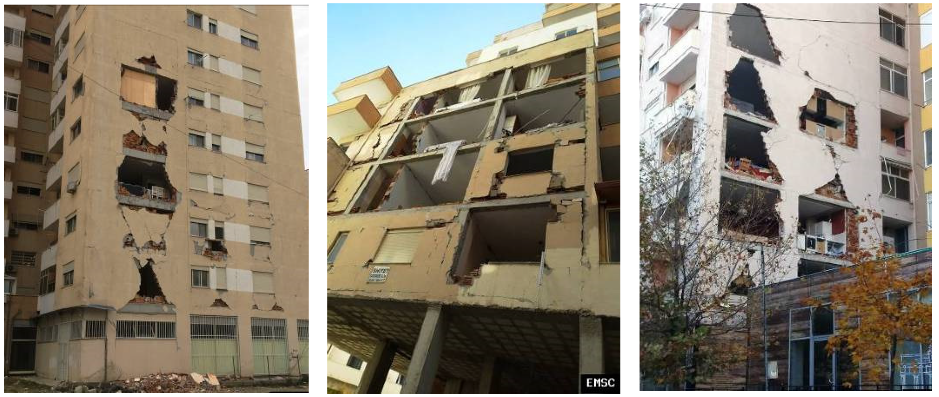
  • Multi-story frame old RC buildings in earthquake-active regions that have soft stories at their ground floor and UMI at all upper stories are quite vulnerable and prone to serious damage to their RC columns of this level. A retrofit aiming to counter this particular deficiency is the addition of RC infill panels at the bays of the ground floor RC frames together with RC jackets of the adjacent RC columns. This particular retrofit, when shown to be sufficient, is comparatively less cumbersome and costly compared to other structural interventions which extend to all floors. This is because these bays are left without infills as the ground floor serves as a parking space. When seismic retrofit is required for all floors of a vulnerable building, it becomes quite difficult and expensive and sometimes incompatible with basic functions of the facades and/or the interior, although it is more effective. It also requires the dislocation of the inhabitants for long periods. Seismic retrofit of existing multi-story RC building poses many practical difficulties and therefore requires additional research, despite the progress made so far, in order to validate ingenious and effective solutions. These difficulties differ from country to country as they are linked to a variety of past design and construction practices as well as the legal framework which governs the multiple ownership, which is usually the case in these buildings.

Author Contributions

G.C.M. was the principal investigator responsible for the whole project concept, for the design/execution of all the test sequences, the supervision of all the tests, the recording and analysis of all the experimental results, the writing of the manuscript and the observations and the conclusions drawn. K.K. participated in the experimental sequence and the study of the measured response. V.S. contributed the numerical investigation. L.M. contributed in plotting of the measurements and in the preparedness of this manuscript. All authors have read and agreed to the published version of the manuscript.

Funding

This research had the partial support of the Hellenic Earthquake Preparedness and Planning Organization (OASP).

Data Availability Statement

Any additional information can be requested by the authors.

Conflicts of Interest

The authors declare no conflict of interest.

References

  1. Manos, G. Consequences on the urban environment in Greece related to the recent intense earthquake activity. Int. J. Civ. Eng. Archit. 2011, 5, 1065–1090. [Google Scholar]
  2. Manos, G.C. The 30th of October Samos-Greece Earthquake. Issues relevant to the protection of structural damage caused by strong earthquake ground motions. J. Archit. Eng. 2020, 5, 3–17. Available online: https://aej.spbgasu.ru/index.php/AE (accessed on 1 January 2020). [CrossRef]
  3. Manos, G.C.; Papanaoum, E. Earthquake behaviour of a R/C building constructed in 1933 before and after its repair. In Proceedings of the Structural Studies Repairs and Maintenance of Heritage Architecture STREMAH XI, Tallin, Estonia, 22–24 June 2009; WIT Transactions on the Built Environment. WIT Press: Southampton, UK, 2009; Volume 109, pp. 465–475, ISBN 978-1-84564-196-2. Available online: www.witpress.com (accessed on 20 October 2022).
  4. Manos, G.C.; Papanaoum, E. Assessment of the earthquake behaviour of Hotel Ermionio in Kozani, Greece constructed in 1933 before and after its recent retrofit. In Earthquake Engineering Retrofitting of Heritage Structures, Design and Evaluation of Strengthening Techniques; Syngellakis, S., Ed.; Wessex Institute of Technology: Southampton, UK, 2013; pp. 25–40. ISBN 978-1-84564-754-4. eISBN 978-1-84564-755-1. [Google Scholar]
  5. Organization of Earthquake Planning and Protection of Greece (OASP). Guidelines for Level—An Earthquake Performance Checking of Buildings of Public Occupancy; OASP: Athens, Greece, 2001. [Google Scholar]
  6. Provisions of Greek Seismic Code. Organization of Earthquake Planning and Protection of Greece (OASP), Dec. 1999; Revisions of Seismic Zonation Introduced in 2003, Government Gazette, Δ17α /115/9/ΦΝ275, Νο. 1154; OASP: Athens, Greece, 2003. [Google Scholar]
  7. EN 1998-1/2005-05-12; Eurocode 8: Design of Structures for Earthquake Resistance—Part1: General Rules, Seismic Actions and Rules for Buildings. European Committee for Standardization: Brussels, Belgium, 2004.
  8. Ruggieri, S.; Chatzidaki, A.; Vamvatsikos, D. Reduced-order models for the seismic assessment of plan-irregular low-rise frame buildings. Earthq. Eng. Struct. Dyn. 2022, 51, 3327–3346. [Google Scholar] [CrossRef]
  9. Ruggieri, S.; Francesco Porco, F.; Uva, G. A practical approach for estimating the floor deformability in existing RC buildings: Evaluation of the effects in the structural response and seismic fragility. Bull. Earthq. Eng. 2020, 18, 2083–2113. [Google Scholar] [CrossRef]
  10. Valente, M.; Milani, G. Alternative retrofitting strategies to prevent the failure of an under-designed reinforced concrete frame. Eng. Fail. Anal. 2018, 89, 271–285. [Google Scholar] [CrossRef]
  11. Holmes, M. Steel Frames with Brickwork and Concrete Infilling. Proc. Inst. Civ. Eng. 1961, 19, 473–478. [Google Scholar] [CrossRef]
  12. Holmes, M. Combined Loading on Infilled Frames. Proc. Inst. Civ. Eng. 1963, 25, 31–38. [Google Scholar] [CrossRef]
  13. Smith, B.S. Behaviour of Square Infilled Frames. J. Struct. Div. 1966, 92, 381–404. [Google Scholar] [CrossRef]
  14. Mallick, D.V.; Severn, R.T. The behaviour of infilled frames under static loading. Proc. Inst. Civ. Eng. 1967, 38, 639–656. [Google Scholar] [CrossRef]
  15. Smith, B.S.; Carter, C. A Method of Analysis for Infilled Frames. Proc. Inst. Civ. Eng. 1969, 44, 31–48. [Google Scholar]
  16. Mainstone, R.J. Supplementary Note on the Stiffnesses and Strengths of Infilled Frames; Current Paper CP 13/74; Building Research Station: Watford, UK, 1974. [Google Scholar]
  17. Klingner, R.E.; Bertero, V.V. Infilled Frames in Earthquake—Resistant Construction; EERC, Report No. 76-32; University of California: Berkeley, CA, USA, 1976. [Google Scholar]
  18. Zarnic, R.; Tomazevic, M. The Behaviour of Masonry Infilled Reinforced Concrete Frames Subjected to Cyclic Lateral Loading. In Proceedings of the 8WCEE, San Francisco, CA, USA, 21–28 July 1984. [Google Scholar]
  19. Styliniades, K. Experimental Investigation of the Behaviour of Single-Story Infilled R/C Frames under Cyclic Quasi-Static Horizontal Loading (Parametric Analysis). Ph.D. Thesis, Department of Civil Engineering, Aristotle University of Thessaloniki, Thessaloniki, Greece, 1985. [Google Scholar]
  20. Pook, L.L.; Dawe, J.L. Effects of interface conditions between a masonry shear panel and surrounding steel frame. In Proceedings of the 4th Canadian Masonry Symposium, Fredericton, NB, Canada, 2–4 June 1986; University of New Brunswick Press: Fredericton, NB, Canada, 1986; pp. 910–921. [Google Scholar]
  21. Buonopane, S.G.; White, R.N. Pseudo-dynamic testing of masonry infilled reinforced concrete frame. J. Struct. Eng. 1999, 125, 578–589. [Google Scholar] [CrossRef]
  22. Da Porto, F.; Grendene, M.; Mosele, F.; Modena, C. In-plane cyclic behaviour of load bearing masonry walls. In Proceedings of the 7th International Masonry Conference, London, UK, 30 October–1 November 2006. [Google Scholar]
  23. Thauampteh, J. Experimental Investigation of the Behaviour of Single-Story R/C Frames Infills, Virgin and Repaired, under Cyclic Horizontal Loading. Ph.D. Thesis, Department of Civil Engineering, Aristotle University of Thessaloniki, Thessaloniki, Greece, 2009. (In Greek). [Google Scholar]
  24. Dhanasekar, D.; Page, A.W. The influence of brick masonry infill properties on the behaviour of infilled frames. Proc. Inst. Civ. Eng. 1986, 81, 593–605. [Google Scholar]
  25. Lourenco, P.B. Computational Strategies for Masonry Structures. Ph.D. Thesis, Delft University of Technology, Delft, The Netherlands, 1996. [Google Scholar]
  26. Lourenco, P.; Rots, J.G. On the Use of Micro-Models for the Analysis of Masonry Shear-Walls; Pande, G.N., Middleton, J., Eds.; Computer Methods in Structural Masonry-2; Books & Journals International: Swansea, UK, 1993; pp. 14–25. ISBN 187414902X, 9781874149026. [Google Scholar]
  27. Mehrabi, A.B.; Shing, P. Finite element modelling of masonry-infilled RC frames. J. Struct. Eng. 1997, 123, 604–613. [Google Scholar] [CrossRef]
  28. Karapitta, L.; Mouzakis, H.; Carydis, P. Explicit finite element analysis for the in-plane cyclic behaviour of unreinforced masonry structures. Earthq. Eng. Struct. Dyn. 2011, 40, 175–193. [Google Scholar] [CrossRef]
  29. Arnau, O.; Sandoval, C.; Murià-Vila, D. Determination and validation of input parameters for detailed micro- modelling of partially grouted reinforced masonry walls. In Proceedings of the Tenth Pacific Conference on Earthquake Engineering, Sydney, Australia, 6–8 November 2015; Volume 101. [Google Scholar]
  30. Sandoval, C.; Arnau, O. Experimental characterization and detailed micro-modeling of multi-perforated clay brick masonry structural response. Mater. Struct. 2017, 50, 34. [Google Scholar] [CrossRef]
  31. Bolhassani, M.; Hamid, A.A.; Lau, A.C.; Moon, F. Simplified micro modeling of partially grouted masonry assemblages. Constr. Build. Mater. 2015, 83, 159–173. [Google Scholar] [CrossRef]
  32. Malomo, D.; DeJong, M.J.; Penna, A. A Homogenized Distinct Macro-Block (HDM) Model for Simulating the In-Plane Cyclic Response of URM Walls. In Proceedings of the 13th North American Masonry Conference, Salt Lake City, UT, USA, 16–19 June 2019; Volume 1, pp. 1042–1054. [Google Scholar]
  33. Ghosh, A.K.; Amde, A.M. Finite Element Analysis of Infilled Frames. J. Struct. Eng. 2002, 128, 881–889. [Google Scholar] [CrossRef]
  34. Asteris, P.G.; Antoniou, S.T.; Sophianopoulos, D.S.; Chrysostomou, C.Z. Mathematical Macromodeling of Infilled Frames: State of the Art. J. Struct. Eng. 2011, 137, 1508–1517. [Google Scholar] [CrossRef]
  35. Asteris, P.G.; Cotsovos, D.M.; Chrysostomou, C.Z.; Mohebkhah, A.; Al-Chaar, G.K. Mathematical micromodeling of infilled frames: State of the art. Eng. Struct. 2013, 56, 1905–1921. [Google Scholar] [CrossRef]
  36. Dias-Oliveira, J.; Rodrigues, H.; Asteris, P.G.; Varum, H. On the Seismic Behaviour of Masonry Infilled Frame Structures. Buildings 2022, 12, 1146. [Google Scholar] [CrossRef]
  37. Manos, G.C.; Yasin, B.; Thawambteh, J. The Dynamic Response of Multi-story R.C. Frame Structures with Masonry Infills. A Laboratory tested 7-Story R.C. Planar Model and an In-situ 5-story Building at the European Test Site at Volvi, Greece. In Proceedings of the 4th Internernational Symposium on Computer Methods in Structural Masonry, Florence, Italy, 3–5 September 1997. [Google Scholar]
  38. Manos, G.C.; Yasin, B.; Thaumpta, J. The Simulated Earthquake Response of two 7-story R.C. Planar Model Structures—A Shear Wall and a Frame with Masonry Infills. In Proceedings of the 1998 11th European Earthquake Engineering Conference, Paris, France, 6–11 September 1998. [Google Scholar]
  39. Manos, G.C.; Pitilakis, K.D.; Sextos, A.G.; Kourtides, V.; Soulis, V.; Thauampteh, J. Field experiments for monitoring the dynamic soil-structure-foundation response of model structures at a Test Site. J. Struct. Eng. Am. Soc. Civ. Eng. 2015, 141, D4014012. [Google Scholar] [CrossRef]
  40. Chiou, Y.C.; Tzeng, J.-C.; Liou, Y.W. Experimental and analytical study of Masonry Infilled Frames. J. Struct. Eng. 1999, 125, 1109–1116. [Google Scholar] [CrossRef]
  41. Soulis, V. Investigation of the Numerical Simulation of Masonry Infilled R/C Frame Structures under Seismic Type Loading. Ph.D. Thesis, Department of Civil Engineering, Aristotle University of Thessaloniki, Thessaloniki, Greece, 2009. (In Greek). [Google Scholar]
  42. Da Porto, F.; Guidi, G.; Garbin, G.; Modena, C. In-plane behaviour of clay masonry walls: Experimental testing and finite element modelling. J. Struct. Eng. 2010, 136, 1379–1392. [Google Scholar] [CrossRef]
  43. Domede, N.; Sellier, A. Experimental and numerical analysis of behaviour of old brick masonries. Adv. Mater. Res. 2010, 133–134, 307–312. [Google Scholar] [CrossRef]
  44. Manos, G.C.; Soulis, V.J.; Thauampteh, J. The Behaviour of Masonry Assemblages and Masonry-infilled R/C Frames Subjected to Combined Vertical and Cyclic Horizontal Seismic-type Loading. J. Adv. Eng. Softw. 2011, 45, 213–231. [Google Scholar] [CrossRef]
  45. Del Vecchio, C.; Molitierno, C.; Di Ludovico, M.; Verderame, G.M.; Prota Manfredi, G. Experimental response and numerical modelling of two-story infilled RC fame. In Proceedings of the CompDyn2021, Athens, Greece, 27–30 June 2021; pp. 131–140. [Google Scholar]
  46. Lavado, L.; Gallardo, J.; Honma, C. Experimental and numerical analysis of behaviour in compression and shear of handmade clay brick masonry. In Proceedings of the 17th World Conference in Earthquake Engineering, Sendai, Japan, 13–18 September 2020. Paper 2i-0141. [Google Scholar]
  47. Manos, G.C.; Soulis, V.J.; Thauampteh, J. A Nonlinear Numerical Model and its Utilization in Simulating the In-Plane Behaviour of Multi-Story R/C frames with Masonry Infills. Open Constr. Build. Technol. J. 2012, 6 (Suppl. S1-M16), 254–277. [Google Scholar] [CrossRef] [Green Version]
  48. Manos, G.C.; Soulis, V. Simulation of the in-plane seismic behaviour of masonry infills within Multi-story Reinforced Concrete Framed Structures. In Proceedings of the 9th International Masonry Conference, Guimarães, Portugal, 7–9 July 2014. [Google Scholar]
  49. Rastegarian, S.; Sharifi, A. An Investigation on the Correlation of Inter-story Drift and Performance Objectives in Conventional RC Frames. Emerg. Sci. J. 2018, 2, 140–147. [Google Scholar] [CrossRef]
  50. Umar, M.; Shah, S.A.A.; Shahzada, K.; Naqash, M.T.; Ali, W. Assessment of Seismic Capacity for Reinforced Concrete Frames with Perforated Unreinforced Brick Masonry Infill Wall. Civ. Eng. J. 2020, 6, 2397–2415. [Google Scholar] [CrossRef]
  51. Rahem, A.; Djarir, Y.; Noureddine, L.; Tayeb, B. Effect of Masonry Infill Walls with Openings on Nonlinear Response of Steel Frames. Civ. Eng. J. 2021, 7, 278–291, E-ISSN 2476-3055. [Google Scholar] [CrossRef]
  52. Romano, F.; Alam, M.S.; Zucconi, M.; Faggela, M.; Barbosa, A.; Ferracuti, B. Seismic loss analysis of Code-designed infilled RC buildings accounting for model class uncertainty. In Proceedings of the CompDyn2021, Athens, Greece, 27–30 June 2021; pp. 102–110. [Google Scholar]
  53. Carydis, P.G.; Mouzakis, H.P.; Taflambas, J.M.; Vougioukas, E.A. Response of infilled frames with brick walls to earthquake motions. In Proceedings of the 10th World Conference Earthquake Engineering, Madrid, Spain, 19–24 July 1992; pp. 2829–2834. [Google Scholar]
  54. Cavaleri, L.; Zizzo, M.; Asteris, P.G. Residual out-of-plane capacity of infills damaged by in-plane cyclic loads. Eng. Struct. 2020, 209, 109957. [Google Scholar] [CrossRef]
  55. Di Domenico, M.; Paolo Ricci, P.; Verderame, G.M. Effect of In-plane/Out-of-plane interaction in infill walls on the floor spectra of Reinforced Concrete Buildings. In Proceedings of the CompDyn2021, Athens, Greece, 27–30 June 2021; pp. 84–101. [Google Scholar]
  56. Sugiyama, T.; Matsuzaki, Y.; Nakano, K. Design for Structural Performances of R/C Frame with Cast in Place Non-Structural R/C Walls. Paper No. 1277. In Proceedings of the 13th World Conference on Earthquake Engineering, Vancouver, BC, Canada, 1–6 August 2004. [Google Scholar]
  57. Choi, C.S.; Lee, H.Y. Rehabilitation of Reinforce Concrete Frames with Reinforced Concrete Infills. Eng. Mater. 2006, 324–325, 635–638. [Google Scholar] [CrossRef]
  58. Anil, O.; Altin, S. Rnq1: An experimental study on reinforced concrete partially infilled frames. Eng. Struct. 2007, 29, 449–460. [Google Scholar] [CrossRef]
  59. Altin, S.; Anil, O.; Kara, M.E. Strengthening of RC nonductile frames with RC infills: An experimental study. Cem. Concr. Compos. 2008, 30, 612–621. [Google Scholar] [CrossRef]
  60. Manos, G. Investigation of the behaviour of RC infilled frames at the ground floor of buildings subjected to cyclic seismic-type loads—Study of the connections of the RC infills with the surrounding frame retrofitted with RC jackets. Internal Report submitted to the Greek Organization of Earthquake Planning and Protection. 2012. (In Greek).
  61. Manos, G.C.; Soulis, V.; Katakalos, K.; Koidis, G. Numerical and Experimental study of seismic retrofitting for one-bay single-story reinforced concrete (R/C) frames with an encased R/C panel. Comput. Methods Exp. Meas. XVI J. 2013, 55, 39–411. [Google Scholar]
  62. Manos, G.C.; Soulis, V.; Katakalos, K.; Koidis, G. Study of the in-plane behaviour of ground floor reinforced concrete (R/C) frames retrofitted with jacketing and an encased R/C Panel in order to withstand seismic forces. In Proceedings of the 4th ECOMASS Thematic Conference on Computational Methods in Structural Dynamics and Earthquake Engineering—COMPDYN 2013, Kos Island, Greece, 12–14 June 2013. [Google Scholar]
  63. Biskinis, D.; Fardis, M.N.; Psaros-Andriopoulos, A. Strength, stiffness and cyclic deformation capacity of RC frames converted into walls by infilling with RC. Bull. Earthq. Eng. 2016, 14, 769–803. [Google Scholar] [CrossRef]
  64. Moretti, M.L.; Papatheocharis, T.; Perdikaris, P.T. Design of Reinforced Concrete Infilled Frames. J. Struct. Eng. 2014, 140, 04014062. [Google Scholar] [CrossRef]
  65. Papatheocharis, T.; Perdikaris, P.T.; Moretti, M.L. Response of RC Frames Strengthened by RC Infill Walls: Experimental Study. J. Struct. Eng. 2019, 145, 04019129. [Google Scholar] [CrossRef]
  66. Chrysostomou, C.Z.; Poljansek, M.; Kyriakides, N.; Taucer, F.; Molina, F.J. Pseudo-Dynamic Tests on a Full-Scale Four-Story Reinforced Concrete Frame Seismically Retrofitted with Reinforced Concrete Infilling. Struct. Eng. Int. 2018, 23, 59–166. [Google Scholar] [CrossRef]
  67. Organization of Earthquake Planning and Protection of Greece (OASP). Guidelines for Retrofitting in Reinforced Concrete Buildings; Government Gazzette, Δ17α/04/5/ΦΝ 429-1, Νο 42; OASP: Athens, Greece, 20 January 2012. [Google Scholar]
  68. LUSAS 13.3. Finite Element System; FEA Ltd.: Kingston, UK, 2000. [Google Scholar]
  69. SAP. Structural Analysis Program; Computer and Structure Inc.: Walnut Creek, CA, USA, 2000. [Google Scholar]
  70. RCCola, R.C.; Mahin, S.; Bertero, V. A Computer Program for Reinforced Concrete Column Analysis; User’s Manual and Documentation; Department of Civil Engineering, University of California: Berkeley, CA, USA, 1977. [Google Scholar]
  71. EN 1992-1-1; Eurocode 2: Design of Concrete Structures—Part 1.1: General rules and rules for buildings. CEN: Brussels, Belgium, 2004.
  72. ASTM E519-15; Standard Test Method for Diagonal Tension (Shear) in Masonry Assemblages. American Society for Testing Material: West Conshohocken, PA, USA, 2015.
  73. Focardi, F.; Manzini, E. Cyclic and Monotonic Diagonal Tension Tests on Various Shape Reinforced and Non-Reinforced Brick Panels. In Proceedings of the 8th European Conference on Earthquake Engineering, Lisbon, Portugal, 7–12 September 1986; Volume 4. [Google Scholar]
  74. Malm, R. Predicting Shear Type Crack Initiation and Growth in Concrete with Non-Linear Finite Element Method. Ph.D. Thesis, Department of Civil and Architectural Engineering, Royal Institute of Technology (KTH), Stockholm, Sweden, 2009. [Google Scholar]
  75. Mercan, B.; Schultz, A.E.; Stolarski, H.K. Finite element modeling of pre-stressed concrete spandrel beams. Eng. Struct. 2010, 32, 2804–2813. [Google Scholar] [CrossRef]
Figure 1. Damaged columns at the soft story.
Applsci 12 11597 g001
Figure 2. Temporary wooden story. Damaged shear wall at the soft story.
Applsci 12 11597 g002
Figure 3. Damaged columns at the soft-story and temporary steel shoring.
Applsci 12 11597 g003
Figure 4. Damaged short columns from the interaction of unreinforced masonry infills (UMI), built within the bay of an RC frame structure, with the adjacent RC columns.
Applsci 12 11597 g004
Figure 5. (a) UMI as a diagonal strut. (b) Shear-sliding failure of UMI.
Applsci 12 11597 g005
Figure 6. Structural details of the RC frame models hosting UMI tested at Aristotle University [23,44].
Applsci 12 11597 g006
Figure 7. RC frame + UMI specimen F3NP [23] (a) before applying the mortar facades. (b) attaching the wire net. (c) applying the cement mortar hosting the wire net to produce (Last row of Table 2).
Applsci 12 11597 g007
Figure 8. (a) The loading arrangement for F2N-UMI specimen (second row of Table 2) (b) The loading arrangement for F3NP- UMI specimen after having applied the cement mortar with the wire net (last row of Table 2). (c) Observed damage for F2N-UMI specimen (d) Observed damage fir F3NP specimen [23,44].
Applsci 12 11597 g008
Figure 9. Out-of-plane collapse of unreinforced masonry infills (UMI) panles from RC frame structures due to earthquake excitation.
Applsci 12 11597 g009
Figure 10. Specimens Bare J1 (Bare Jacket1) and Bare J2 (Bare Jacket2).
Applsci 12 11597 g010
Figure 11. Specimens UC-IP 2 and RC-IP 3.
Applsci 12 11597 g011
Figure 13. Damage of UC-IP 1, UC-IP 2, and RC-IP 3. (a) Crushing of the UC infill panel and the RC frame at the corner. Specimen UC-IP 1. (b) Large cracking of the UC infill panel. Specimen UC-IP 2 (c) Control of cracking of the reinforced infilled panel. Specimen RC-IP 3.
Applsci 12 11597 g013
Figure 15. (a) Horizontal load cyclic response versus sliding at the contact surface of the concrete infill panel and surrounding frame for specimen UC-IP 1. (b) Horizontal load cyclic response versus sliding or separation at the contact surface of the concrete infill panel and surrounding frame for specimen UC-IP 2. (c). Horizontal load cyclic response versus sliding or separation at the contact surface of the concrete infill panel and surrounding frame for specimen UC-IP 3.
Applsci 12 11597 g015aApplsci 12 11597 g015b
Figure 16. Horizontal load cyclic response versus sliding or separation at the contact surface of the concrete infill panel and surrounding frame for specimens UC-IP 1, UC-IP 2, and RC-IP 3.
Applsci 12 11597 g016
Figure 17. Numerical simulation of the surrounding RC frame with the location of the plastic hinges.
Applsci 12 11597 g017
Figure 18. Horizontal displacement versus horizontal load cyclic response of specimens Bare Jacket1,2.
Applsci 12 11597 g018
Figure 19. (a) Observed damage. (b) Numerically simulated diagonal tension cracking of square concrete panel. (b) Assumed combined compression–tension failure envelope included in the numerical simulation of the square concrete panel subjected to diagonal compression as well as of RC the infilled panels.
Applsci 12 11597 g019
Figure 20. Diagonal compression–tension. (a) Comparison between observed and numerically simulated behaviour of the tested square concrete panels. (b) Predicted plastified regions from the numerical simulation.
Applsci 12 11597 g020
Figure 21. (a) Experimental setup to study the force transfer mechanism between portions of the RC panel and the jacketed RC column with or without steel ties. (b) Cross-section [60,61,62].
Applsci 12 11597 g021
Figure 22. Horizontal displacement versus horizontal load cyclic response of specimen UC-IP 1. Comparison between observed and numerically predicted behaviour.
Applsci 12 11597 g022
Figure 23. (a) The numerically predicted compression limit state for specimen UC-IP 1. (b) The observed damage for specimen UC-IP 1.
Applsci 12 11597 g023
Figure 24. Horizontal displacement versus horizontal load cyclic response of specimen UC-IP 2. Comparison between observed and numerically predicted behaviour.
Applsci 12 11597 g024
Figure 25. (a) The numerically predicted diagonal tension limit state for specimen UC-IP 2. (b) The observed damage for specimen UC-IP 2.
Applsci 12 11597 g025
Figure 26. Horizontal displacement versus horizontal load cyclic response of specimen RC-IP 3. Comparison between observed and numerically predicted behaviour.
Applsci 12 11597 g026
Figure 27. (a) The numerically predicted diagonal tension limit state for specimen RC-IP 3. (b) The observed damage for specimen RC-IP 3.
Applsci 12 11597 g027
Table 1. Basic mechanical properties of all the building materials [23].
Concrete Compressive Strength (MPa)Steel Reinforcement Yield/Ultimum Stress (MPa)Clay Brick Compressive Strength (MPa)Mortar Compressive/Tensile Strength (MPa)Masonry Compressive Strength (MPa)Masonry Diagonal Tension Strength (MPa)Compressive Strength of Mortar Applied to the Façade (MPa)
(1)(2)(3)(4)(5)(6)(7)
23.3311/4254.81.13 / 0.122.50.1517.0
Table 2. Summary of the obtained peak response of the bare and the infilled specimens.
Code
Name
Initial hor. Stiffness (kN/mm)Hmax Maximum * Hor. Load (kN)Normalized ** Inter-Story Drift at HmaxCumulative Plastic Energy Till Hmax (kN/mm)Initial Stiffness Ratio ***Maximum Hor. Load Ratio ***Cumulative Energy Ratio ***
(1)(2)(3)(4)(5)(6)(7)(8)
Bare F1BN8.7515.201.04%472/10 mm111
Decrease Hor. Load 12.502.65%1927/25 mm
F2N infilled22.1235.300.80%924/8 mm2.532.321.96
Further testing stopped
F3NP infilled77.8478.100.80%2743/8 mm8.905.145.81
Decrease Hor. Load 45.002.55%8076/25 mm
* Average value of measured minimum and maximum load. ** Measured hor. displacement at maximum load normalized by the frame height. *** Ratio of the infilled specimen response by the response of the corresponding bare specimen.
Table 3. Summary of the obtained peak response of the Bare and the Infilled specimens.
Code
Name
Initial Hor. Stiffness (kN/mm)Hmax Maximum * Hor. Load (kN)Normalized ** Inter-Story Drift at HmaxCumulative Plastic Energy Till Hmax (kN/mm)Initial Stiffness Ratio ***Maximum Hor. Load Ratio ***Cumulative Energy Ratio ***
(1)(2)(3)(4)(5)(6)(7)(8)
Bare 1211.121.48%1241.86.011.1811.3
UC-IP 112124.300.7%14,048.6
Bare jacket113.355.811.48%7574.35.266.061.98
UC-IP 270338.41.48%15,028.3
Bare jacket23.252.992.4%5913.418.757.710.75
RC-IP 360408.252.86%63,597.9
* Average value of measured minimum and maximum load. ** Measured hor. displacement at maximum load normalized by the frame height. *** Ratio of the Infilled specimen response by the response of the corresponding Bare specimen.
Publisher’s Note: MDPI stays neutral with regard to jurisdictional claims in published maps and institutional affiliations.

