Article

Application of Graphene Oxide as a Biomaterial for the Development of Large-Area Cell Culture Vessels

1
School of Convergence & Fusion System Engineering, Institute of Global Climate Change and Energy, Kyungpook National University, Gajang-dong 386, Sangju 37224, Republic of Korea
2
Joint Institute for Regenerative Medicine, Kyungpook National University, Dongdeok-ro 135, Jung-gu, Daegu 41944, Republic of Korea
3
Central Research Center, Corestem Inc., 255 Pangyo-ro, Seoul 13486, Republic of Korea
4
Biomedical Research Institute, Joint Institute for Regenerative Medicine, Kyungpook National University Hospital, Kyungpook National University School of Medicine, Dongdeok-ro 135, Jung-gu, Daegu 41944, Republic of Korea
*
Authors to whom correspondence should be addressed.
Appl. Sci. 2022, 12(22), 11599; https://doi.org/10.3390/app122211599
Submission received: 21 October 2022 / Revised: 10 November 2022 / Accepted: 11 November 2022 / Published: 15 November 2022
(This article belongs to the Special Issue Bio-Materials in Regenerative Medicine)

Abstract

:
In this study, graphene oxide (GO) was coated on the surface of a large-area polystyrene film using spray coating. To analyze the possibility of developing a large-area cell culture vessel from this material, the mechanical properties of the coated surface as well as the cell compatibility and cell proliferation in the vessel were evaluated. Step measurements confirmed a curve of 100 nm or larger on the cell culture vessel surface. The surface was composed of GO (as determined from Raman spectroscopy) and its measured transmittance was ~90% or higher. The coated surface was rendered hydrophilic with an increase in surface energy. Although the cells hardly grew on the general polystyrene film, they attached and proliferated on the polystyrene film coated with GO. Zero cytotoxicity was reported, particularly in the sample that was spray-coated three times at 93.75 mm/s. Note that the cell viability was 1.43 times higher than that in the conventional cell culture vessel. Economic and efficient large-area cell culture vessels can be developed if the GO coating establishes an appropriate surface roughness and surface energy.

1. Introduction

Graphene and graphene oxide (GO) are known as “dream nanomaterials” owing to their excellent thermal and electrical conductivity and high mechanical strength [1,2,3]. In the early days, GO was known only as an intermediate in the mass production of graphene, so graphene was regarded as a substance with more potential. However, GO has since become recognized for its excellent mechanical properties and high biocompatibility.
The unique characteristics of GO can be attributed to the structure of graphene. Graphene can be fabricated via various methods, such as the mechanical exfoliation method, chemical synthesis, the CVD growth method, and epitaxy synthesis. Among these methods, chemical exfoliation oxidizes graphite with acid and caused ultrasonic pulverization, which infiltrates water molecules into the hydrophilic graphite oxide generated in the interlayer, thus widening the gap between the carbon side and the carbon side. Graphene oxide is obtained by separating layers using a wide gap. When sp2 bonds are broken and sp3 bonds are formed, multiple oxygen functional groups, such as hydroxyl groups, epoxy groups, carboxyl groups, and ketone groups can bond to the broken parts [4,5,6,7,8,9,10].
Due to various properties of GO such as amphiphilicity, easy surface functionalization, high antiviral activity, and biocompatibility, GO received considerable attention as a good biomaterial for biomedical applications, including cell culture plates, biosensors, and more recently, filter materials, that inactivate the COVID-19 virus [11,12,13,14]. The advantages of GO, unlike other metals such as molybdenum and titanium, include non-toxicity, being harmless to the human body, and physicochemical properties similar to metals despite being a nonmetal. In addition, the physical properties of the GO matrix are known to promote the adhesion, proliferation, and differentiation potential of progenitor cells [15,16]. Previously, our team investigated the characteristics of GO and the development of the coating process to assess the viability of GO as a biomaterial for efficient cell culture vessels [17]. The study confirmed that a GO coating on the plastic cell culture plate induced fast cell attachment and increased cell proliferation efficiency. Moreover, this coating process is rapid, relatively simple, and economic. It demonstrated its potential as a high-efficiency method of producing cell culture plates [18,19].
In the previous study, GO was coated on the surface of polystyrene cell-culture vessels with a diameter of 35 mm. The earlier results highlighted the requirement for the deposition of GO on a large area in a cell culture system that must be mass-produced for clinical applications. In order to increase the cell culture efficiency, the cell adhesion time must be reduced, and the proliferation efficiency increased within the economic constraints of mass production. In this study, we developed the GO-coated plate in a large area and investigated its coating properties. The physiochemical analysis was performed with Raman spectroscopy, surface energy analysis, contact angle analysis, and surface transparency [20]. Biological analysis was performed on cell cultures using human fibroblast cells and human bone marrow-derived mesenchymal stem cells, followed by cell viability, cell proliferation analysis, flow cytometry, and enzyme-linked immunosorbent assay (ELISA).

2. Materials and Methods

2.1. Materials

2.1.1. Graphene Oxide

GO was purchased as an ultra-highly concentrated single-layer GO solution (6.2 mg/mL, hereafter abbreviated to US GO) from Graphene Supermarket (New York, NY, USA), and polystyrene film was obtained from Sigma (Darmstadt, Germany).

2.1.2. Cell Culture Test

For the cell culture tests, fibroblasts (ATCC® PCS201012™, Manassas, VA, USA) were cultured in Dulbecco’s Modified Eagle Medium (DMEM) (WELGENE, Republic of Korea) containing 9% fetal bovine serum (Merck Darmstadt, Germany) and 1% antibiotics. Cell proliferation and cell cytotoxicity were analyzed using a cell counting kit (CCK-8; Dojindo, Kumamoto, Japan) and a live/dead double-staining kit (Abbkine, CA, USA).
Human bone marrow-derived mesenchymal stem cells (hBM-MSCs) were maintained in CSBM-A06 supplemented with 10% FBS and 100 units/mL penicillin and 100 ug/mL streptomycin. Additionally, the cells were incubated at 37 °C in the presence of 5% CO2.

2.2. Equipment

Spraying was performed by a 250+ spray-coating system purchased from Spray Systems Co. (Chicago, IL, USA). Its components are a nozzle and bracket, a conveyor assembly, a tank unit, and a controller (250+) (Figure 1).

2.3. Experimental Method

2.3.1. Spray Coating

The GO solution used for spray coating was diluted with ethanol to prepare 0.5 mg/mL concentration. The concentration of 0.5 mg/mL was determined as the most effective spray concentration out of the 0.1 mg/mL~2 mg/mL range performed in the previous studies [18,19].
Prior to spraying, a (300 × 300) mm2 polystyrene film was placed on a hot plate and preheated for 3 min at 100 °C. The film was sprayed twice. Each spray followed by 30 s of preheating on a hot plate was considered as one spray-coating process. The coating speed was varied as 42.90 (low, L), 71.40 (medium, M), and 93.75 mm/s (high, H), and the number of coatings was varied as 3, 5, and 7, thus yielding nine coating models in total. The models (named after their coating speed and number) are summarized in Table 1. The GO-coated polystyrene film was washed with 30 mL of distilled water and 10 mL of ethanol before use.

2.3.2. Surface Profiling Measuring System

The 3D shape and step difference on the surface of the spray-coated polystyrene film were analyzed using a step profiler (Surface profiler, AlphaStep D-500, Kla-tencor, Milpitas, CA, USA).
The step measurement method forms 2D data by measuring the height difference using the linear movement of a tip with a single arcuate structure. This method can precisely measure the thickness of ultra-fine thin films and the thickness and step differences on soft materials with low mechanical strength.
The surface scanned by the stylus (size 2.5 μm; stylus force 3 mg) of the step measuring instrument was measured using 3D mapping.

2.3.3. Raman Spectroscopy

Raman scattering refers to light scattering that changes the wavelength of light. Raman scattering was first observed as a scattering of green light when blue light was irradiated on a solution. In Raman spectroscopy, the light of a single wavelength is transmitted using a material and the spectral lines of wavelengths other than the transmitted light are observed, thus providing qualitative and quantitative analyses of the vibrational structure of molecules and the measured material. In the Raman analyses of graphene and GO, the number of graphene layers is determined from the G peak, D peak, 2D peak, and the relative intensity ratio (ID/IG) of the D and G bands of graphene. Raman spectroscopy can determine the degree of structural defects.
The presence or absence of GO coating on the surface of the polystyrene film and the characteristics of the coated GO were confirmed using a Raman spectrometer (inVia reflex, Renishaw Co., Wotton-under-Edge, UK). The spectrum was then collected and analyzed.

2.3.4. Ultraviolet/Visible Light Spectrophotometer

The transmittance of the GO-coated polystyrene film surface was measured in the visible-light region (400–700 nm) using an ultraviolet/visible-light (UV/Vis) spectrophotometer (UV-160A, Shimadzu Co., Kyoto, Japan). As the polystyrene film is a transparent material, its coating property was evaluated by measuring the opacity of the coated surface.

2.3.5. Contact Angle Measurements

The contact angle refers to the angle that forms when a liquid and a gas reach a thermodynamic equilibrium on a solid surface when a liquid is dropped on the surface. Currently, when the contact angle is low, the surface energy is high; inversely, when the contact angle is high, the surface energy is low. Hydrophilicity can be determined through surface energy. Therefore, in order to evaluate the change in the hydrophilicity or surface energy of hydrophobic polystyrene film after coating with GO, the contact angle was measured using a drop shape analyzer (DSA100, KRUSS Co., Hamburg, Germany).

2.3.6. Human Fibroblast Cells Culture Test

To evaluate the cell proliferation and cell cytotoxicity of the GO coating, a GO-coated polystyrene film was fixed on a cell culture slide (Figure 2). The GO-coated polystyrene film was selected from a random area on the original (300 × 300) mm2 film and cut to the same size as the slide. The results on the prepared film were compared with those on a cell culture slide coated with GO but no film (positive control) and a sample with no polystyrene film (negative control).
Each well was seeded with 5 × 10⁴ fibroblasts in 500 μL of DMEM medium and cultured for 3 days in a 37 °C CO2 incubator (PANASONIC HCO 18AC-PK, Osaka City, Japan). After culturing, cell proliferation was confirmed on the second and third days following the CCK-8 manufacturer’s protocol. For the CCK-8 kit, 500 μL of CCK-8 reagent mixed with DMEM medium at a ratio of 9: 1 was added to each well, washed twice with PBS, and reacted in a CO2 incubator for 30 min with a multi-plate reader (TECAN SPARK 10 M, Männedorf, Switzerland). Proliferation was assessed by measuring the optical density (OD) of the cell suspensions. For cell cytotoxicity analysis, a staining solution (staining buffer 98% + live dye 1% + dead dye 1%) was added to the double-staining assay kit as per the manufacturer’s protocol and reacted in a CO2 incubator for 15 min. The differently stained live and dead cells were then imaged under a fluorescence microscope (AXIO, ZEISS).
The cell compatibility of the GO-coated plastic surface was determined by comparing the cell proliferation and cell division times after two and three days of cell culturing. The cell proliferation was analyzed using the CCK-8 kit. After reacting each culture with the CCK-8 reagent on the first day, the absorbance at 450 nm was measured using a multiplate reader (TECAN SPARK 10 M, Männedorf, Switzerland). WST-8, a highly water-soluble tetrazolium salt in the CCK-8 reagent, reduces to a yellow formazan dye through intracellular dehydrogenase activity. The amount of yellow formazan dye (as a proxy of cell number) was then determined from the OD value at 450 nm. Cell proliferation was then estimated by comparing the OD values on Days 2 and 3. Cytotoxicity was confirmed using a live/dead assay of cells. Under a fluorescence microscope, the stained live and dead cells had a fluorescence of green and red, respectively.

2.3.7. Human Bone Marrow-Derived Mesenchymal Stem Cells (hBM-MSCs) Culture Test

In the cell culture test and physicochemical analysis using HF cells, the ability of H3 to improve cell culture efficiency was the highest, so hBM-MSCs were tested only with H3 GO substrates. The experimental method using hBM-MSCs is described below.

Cell Viability and Proliferation Analysis

The cell viability and proliferation rate were evaluated using the trypan blue staining method. The same numbers of hBM-MSCs were inoculated on both polystyrene (PS) and graphene-oxide (GO) culture substrates. Following 72 h of incubation, they were detached and stained with trypan blue dye. Then, the live cells (unstained) and dead cells (stained) were counted. The population doubling level (PDL) and population doubling time (PDT) were calculated with the following formula: PDL = log2(Nf/Ni). PDT = CT/PDL. Nf and Ni indicate the final and initial cell numbers, respectively. Additionally, CT refers to culture time (h).

Flow Cytometry

hBM-MSCs cultured on PS or GO substrates for 7 days were harvested and washed with cold DPBS. Then, they stained with eight antibodies (CD29-PE. CD34-PE, CD44-PE, CD45-PE, CD73-PE, CD90-PE, CD105-PE, and HLA-DR-PE) for 30 min at 4 °C in the dark. The cells were analyzed with BD FACSCanto II and FACSDivaTM software. All the used antibodies were obtained from BD Biosciences.

Enzyme-Linked Immunosorbent Assay (ELISA)

hBM-MSCs were incubated on PS or GO culture substrates for 7 days, and the cell supernatants were obtained. The concentration of vascular endothelial growth factor (VEGF) was measured using Human VEGF Quantikine ELISA Kit (DVE00, R&D systems) according to the manufacturer’s instruction.

3. Results

3.1. Step Measurements

The surface roughness and Ra and Rq values of each sample were obtained using step measurements. The Ra is the average roughness (arithmetic mean) relative to the center line, and the Rq value is the root mean square (RMS) of the roughness, which more closely captures the actual surface height than Rq. The Rq is known to be ~10% larger than Ra.
Ra = Y 1 + Y 2 + + Y n n   Y n = amplitude   area   with   respect   to   the   centerline
R q = Y 1 2 + Y 2 2 + + Y n 2 n Y n = amplitude   area   with   respect   to   the   centerline
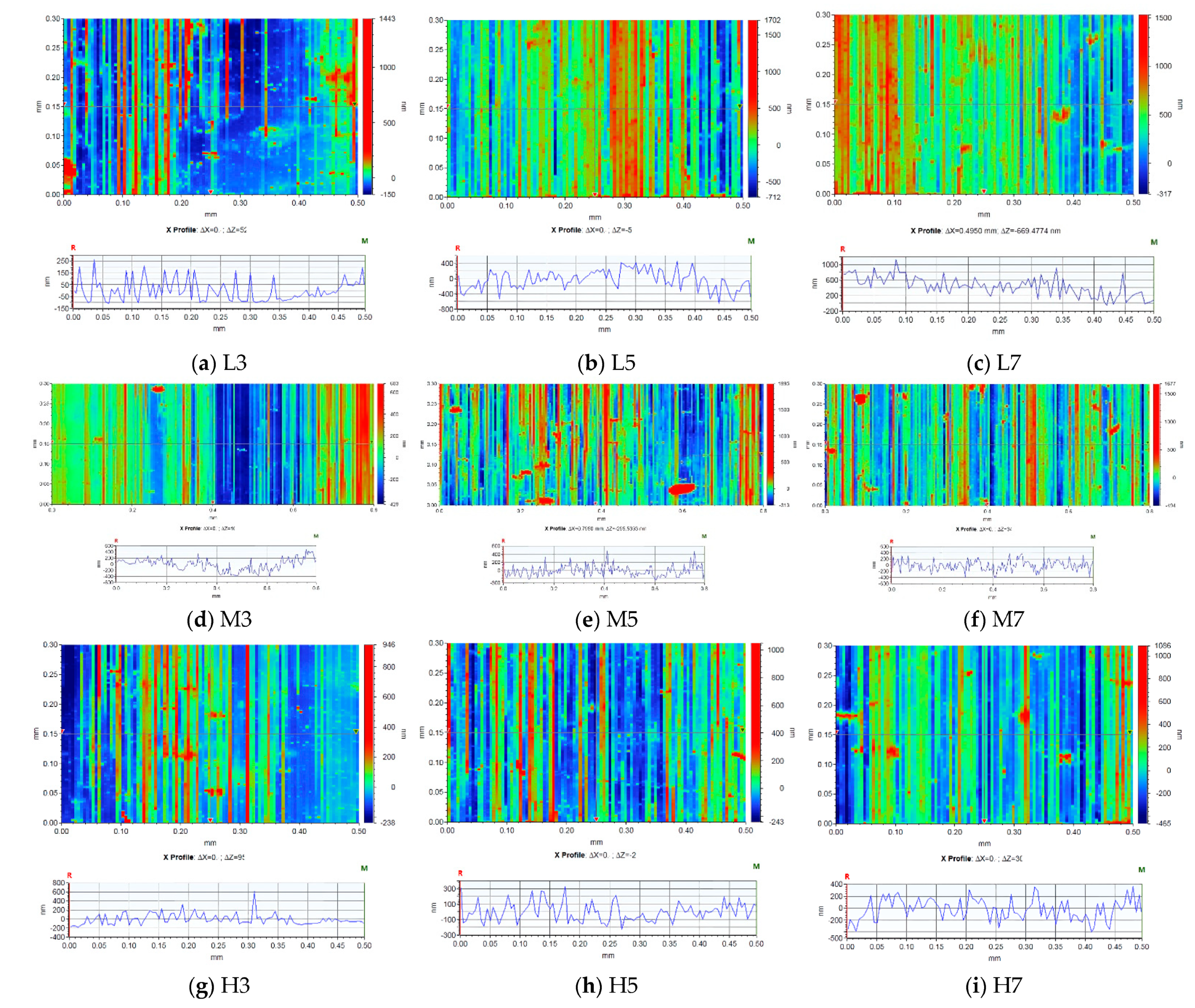
As confirmed in Table 2, increases in the coating speed reduced the roughness values (Ra, Rq) over the entire surface. After three, five, and seven coatings, the roughness values were 73, 210, and 458 nm, respectively, in the L group, increasing to 93, 98, and 148 nm, respectively, in the H group. The mean surface curvatures largely varied in the L group and similarly largely in the M group; however, the number of surface curvatures was higher in the M group than in the other groups (Figure 3).

3.2. Raman Spectroscopy

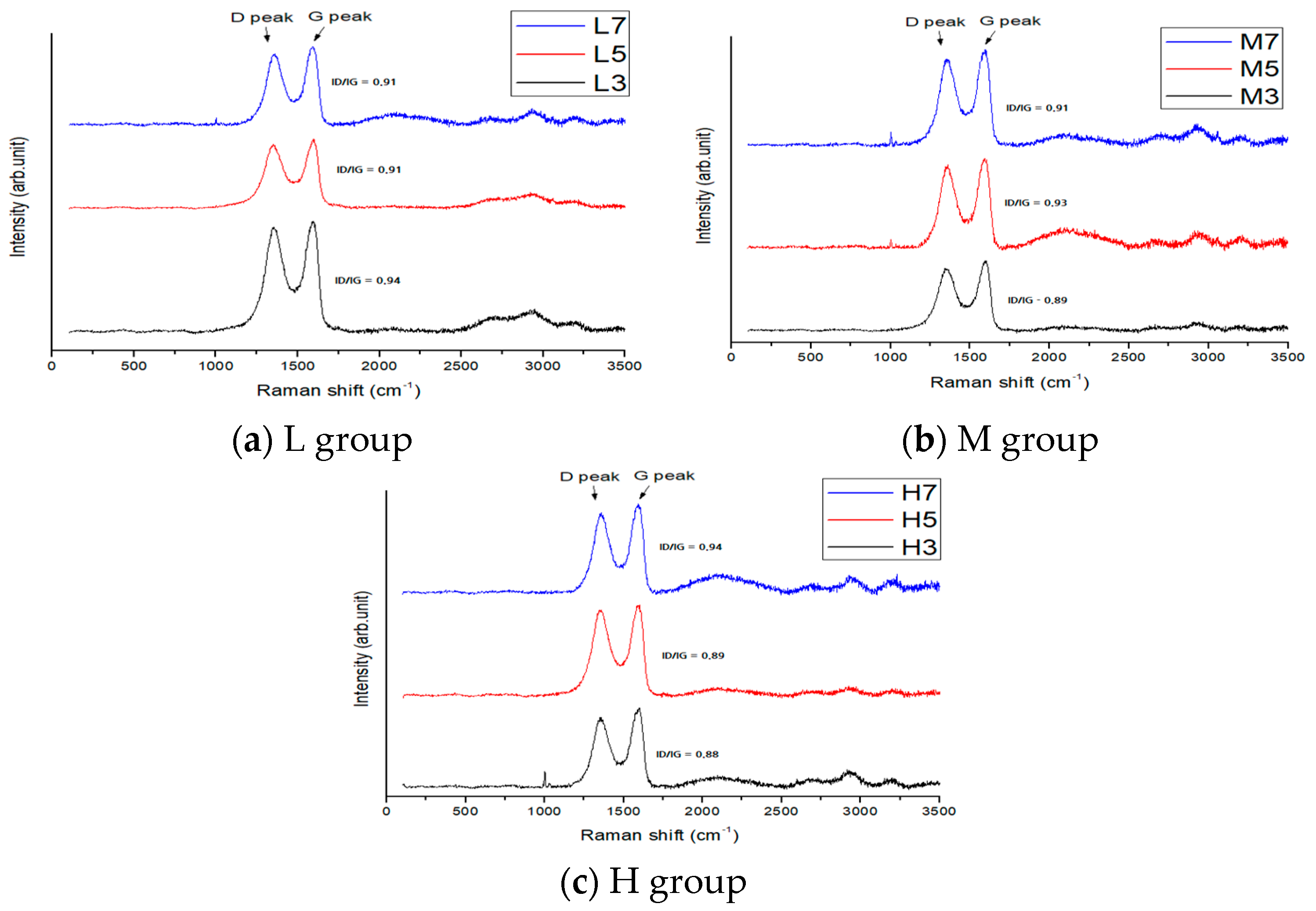
The G peak appeared in the Raman spectra of all spray coatings, confirming that polystyrene was coated with GO. The ID/IG values were 0.94, 0.91, and 0.91 for L3, L5, and L7, respectively, 0.89, 0.93, and 0.91 for M3, M5, and M7, respectively, and 0.88, 0.89, and 0.94 for H3, H5, and H7, respectively (Figure 4). As all models produced the same type of GO, they exhibited similar defects in their spectra.

3.3. Permeability

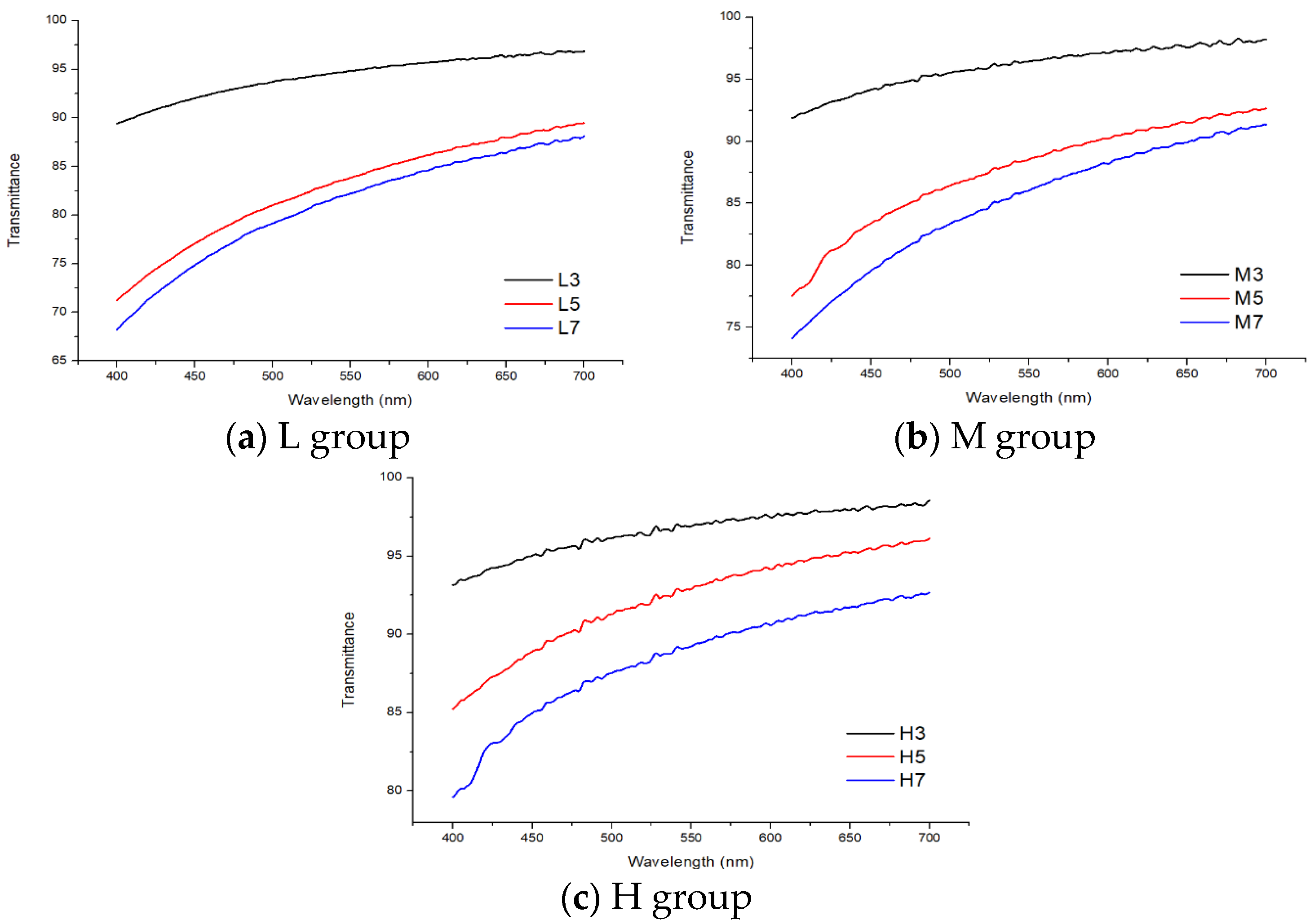
The transmittance values were obtained compared to the polystyrene film not being coated with GO. The average transmittances were 94.3% T, 82.8% T, and 81.0% T in M3, M5, and M7, respectively, 96.0% T, 87.6% T, and 85.1% T in L3, L5, and L7, respectively, and 96.6% T, 92.2% T, and 88.5% T in H3, H5, and H7, respectively (Figure 5). As the number of coatings increased or the progress rate reduced, the GO was more thickly laminated on the polystyrene film surface, and the transmittance was lowered.

3.4. Contact Angle

The contact angle defines the angle at which the liquid–gas interface of a droplet intersects the solid on which the droplet is deposited. It is measured with respect to the liquid phase at the contact point of the solid, liquid, and gas phases. Its value indicates the wettability and surface energy of the solid. A low angle indicates high wettability (hydrophilicity) and high surface energy, whereas a high angle indicates low wettability (high hydrophobicity) and low surface energy.
The contact angles were calculated as the averages of five measurements, each with a 4 μL droplet. The average contact angles were 40.0°, 39.0°, and 39.8° on L3, L5, and L7, respectively, 51.0°, 36.6°, and 38.4° on M3, M5, and M7, respectively, and 54.6°, 36.1°, and 36.0° on H3, H5, and H7, respectively (Figure 6). All GO-coated surfaces had contact angles lower than the conventional polystyrene contact angle of 85.6° (see Table 3). The polystyrene surface, which is hydrophobic, became hydrophilic after spray coating with GO. As cells better adhere to hydrophilic surfaces than hydrophobic surfaces, the GO coating is expected to facilitate cell growth [21].

3.5. Human Fibro Blast Cell’s Viability and Proliferation

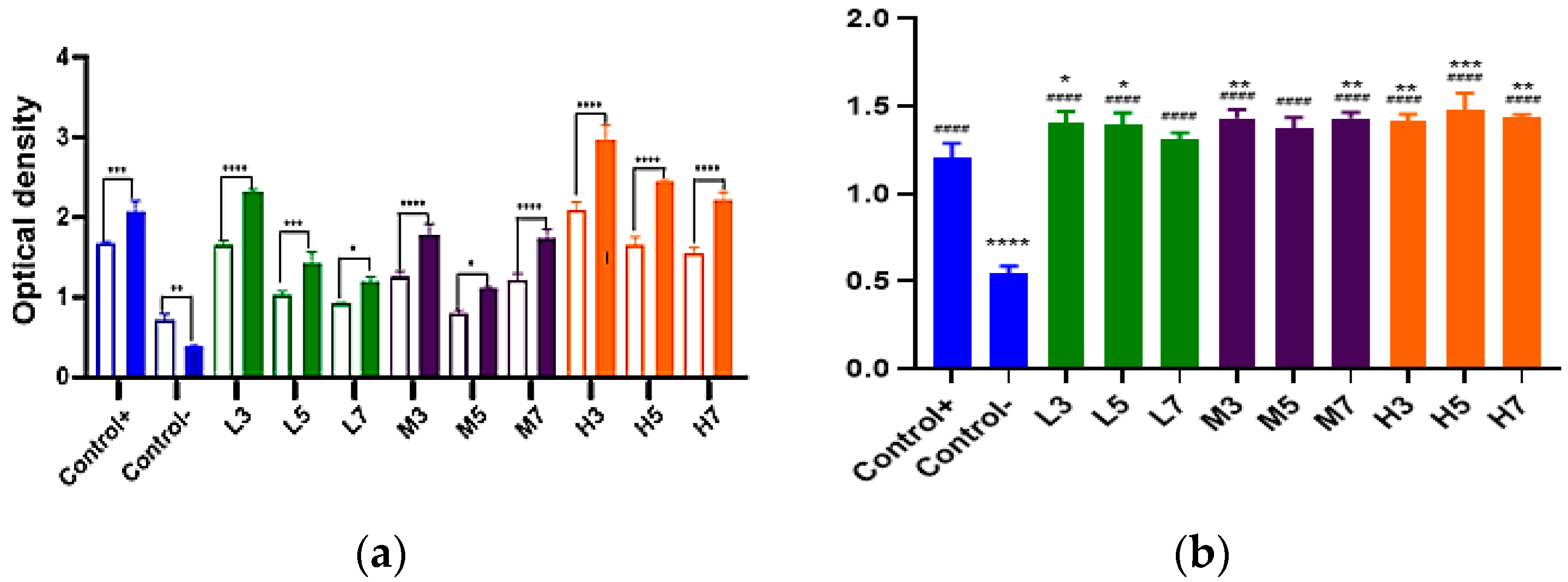
Figure 7 shows the proliferation rates obtained by comparing the OD values of the cultures using the CCK-8 reagent on Days 2 and 3 of culturing on the GO-coated polystyrene film. As pure polystyrene is a hydrophobic material containing only phenyl groups, it is unsuitable for cell adhesion but can be deformed to a hydrophilic state with surface charges for cell culturing [22,23,24]. On the unmodified polystyrene film (negative control), the number of cells decreased between Days 2 and 3 and the cell proliferation rate was 1.0 or lower. However, the cell proliferation rate increased on the PS film coated with GO, regardless of the coating conditions. Among the GO-coated films, L3 and H3 demonstrated obviously higher ODs on Day 3 than on the positive control at Day 3. If the coating conditions of GO are appropriately adjusted, the cell culture efficiency in the CO-coated vessel can exceed that in the existing cell culture vessel, and a large-area cell culture vessel can be expected. Therefore, when developing cell culture vessels, one must select coating conditions that maximize the cell culture efficiency. For this purpose, the optimal conditions of the proposed vessel were selected by comparing the results of physical and biological analyses.
As reported previously, the surface roughness values of the GO-coated polystyrene films tended to increase with the number of coatings. Additionally, the slower the speed, the larger the degree of change was analyzed. However, when comparing the L group and the fastest cell proliferation on the third day of the H group, it was analyzed that the OD value decreased as the number of coatings increased (Figure 8).
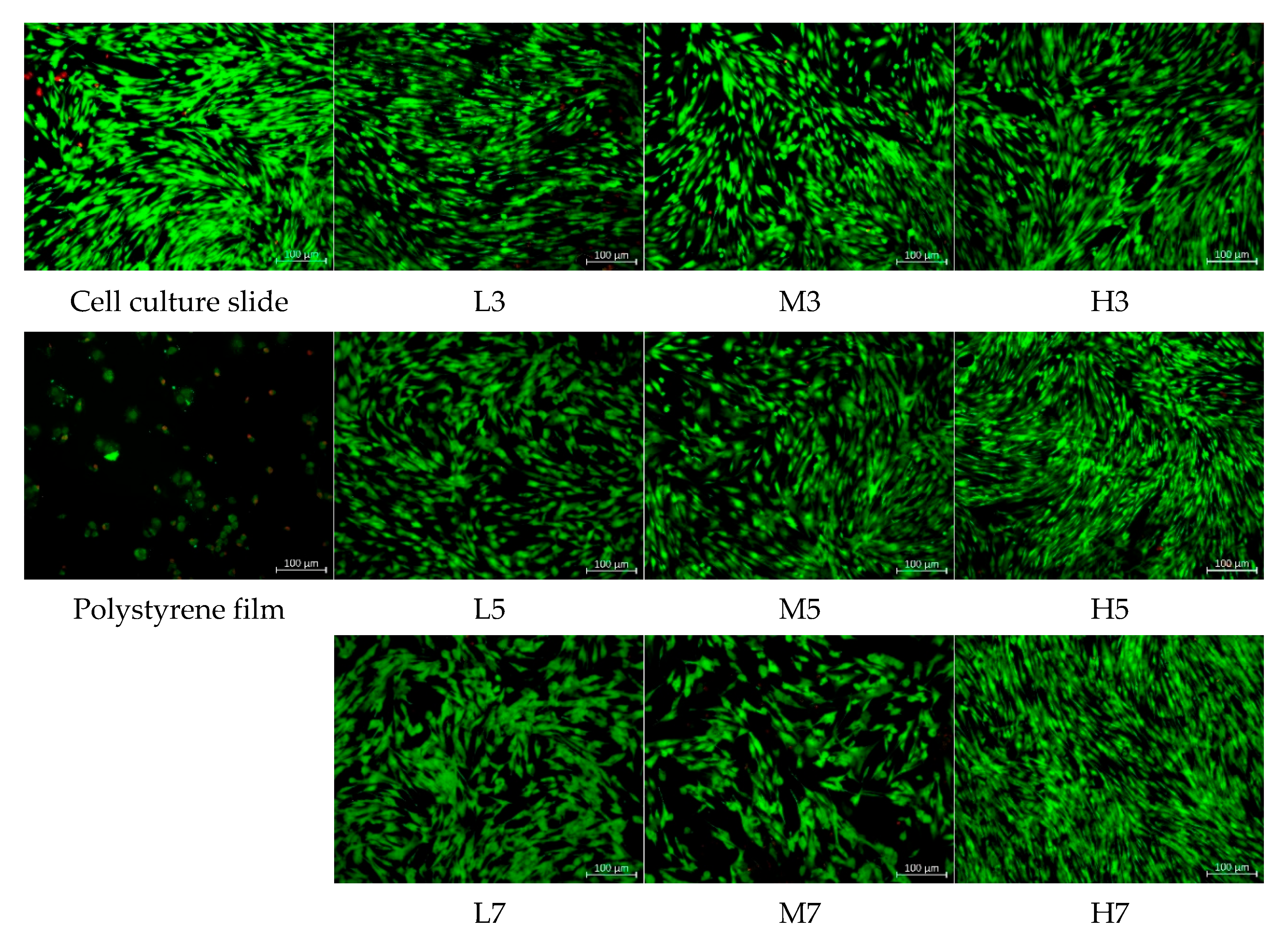
Cell cytotoxicity was confirmed by live/dead assay using a double-staining kit. The images taken under a fluorescence microscope are shown in Figure 9. The live cells emitted green fluorescence (excitation wavelength = 514 nm) while their dead counterparts expressed red fluorescence (excitation wavelength = 561 nm). While the negative control PS film expressed green and red fluorescence at a similar ratio, all samples coated with GO demonstrated insignificant red fluorescence, affirming the non-cytotoxicity of the GO-coated film.
As the GO coating increased the surface energy and surface roughness of the PS film (Table 2 and Table 3), it increased the cell culture efficiency by increasing the initial adhesion and proliferation rate of cells without requiring complex chemical treatment. Unlike the polystyrene film, the GO-coated PS film demonstrated no cytotoxicity and improved the cell compatibility with the vessel surface.

3.6. hBM-MSCs Cell Culture Test

3.6.1. Cell Morphology Analysis

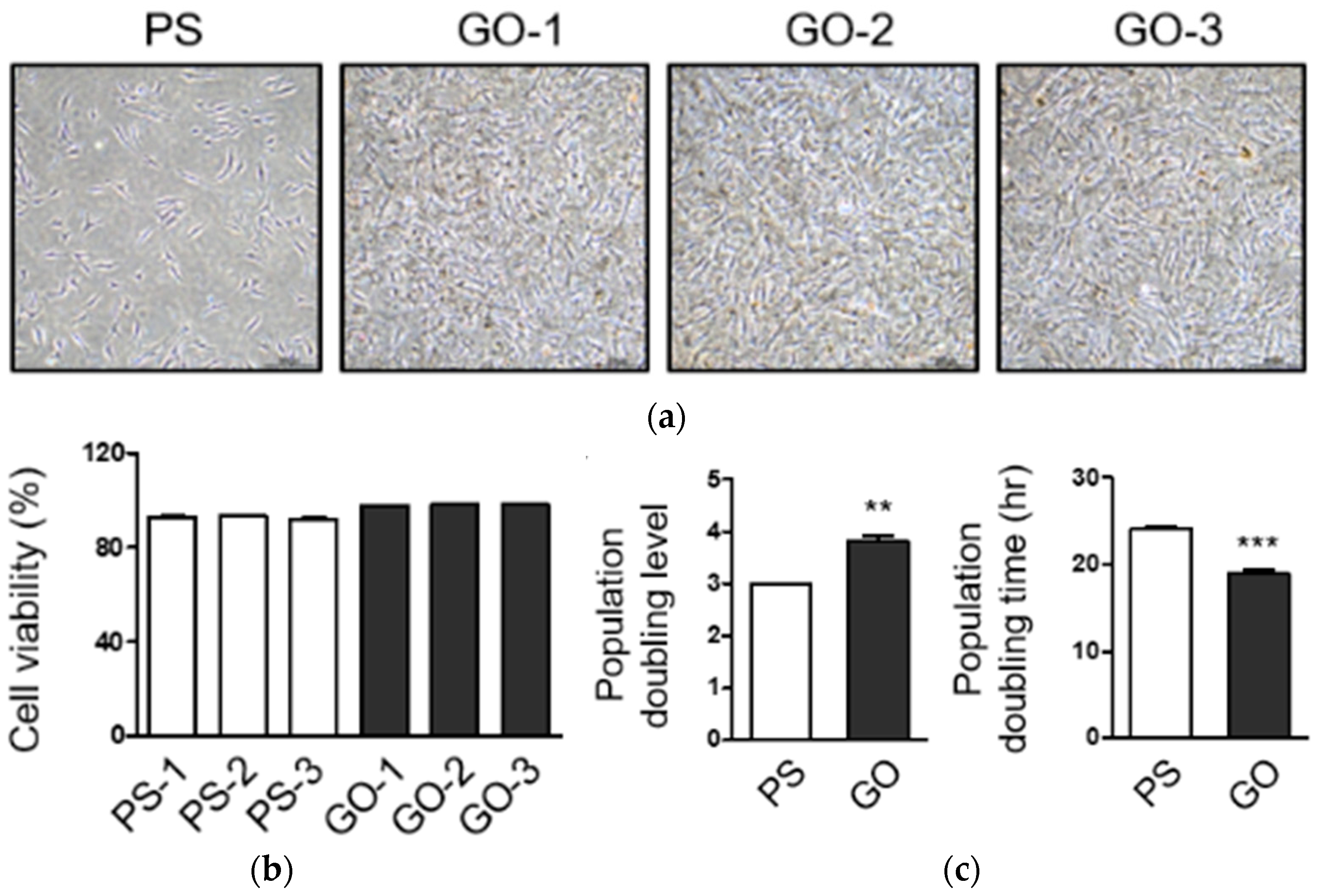
Human bone marrow-derived mesenchymal stem cells (hBM-MSCs) were attached to both polystyrene (PS) and graphene-oxide (GO) substrates. hBM-MSCs are known to have spindle-shaped and fibroblast-like morphology. Additionally, the hBM-MSCs cultured on PS or GO substrates did not appear to have any differences in morphology (Figure 10a). In addition, it was confirmed that the cells cultured on the GO substrates grew faster than the cells cultured on the PS substrates when the cells were observed at the same time point.

3.6.2. Cell Proliferation Analysis

The viability of hBM-MSCs cultivated on both PS and GO substrates was over 90%, and there were no differences between them (Figure 10b). The population doubling level, one of the markers of cell growth, increased by about 27% in cells of GO substrates compared to PS substrates. Additionally, the population doubling time was reduced by approximately 21% in the GO substrates than in the PS substrates (Figure 10c). Therefore, this suggested that hBM-MSCs grow more effectively on the GO substrates than on the PS substrates.

3.6.3. Flow Cytometric Analysis of MSC Markers

To characterize hBM-MSC grown on the GO substrates, the surface markers of BM-MSCs were analyzed using flow cytometry. The expression of MSC positive markers, CD29, CD44, CD73, CD90, and CD105, was all over 95% and of MSC negative markers, CD34, CD45, and HLA-DR was less than 1% (Figure 11). Thus, this indicates that hBM-MSCs retain MSC-specific properties on GO culture substrates.

3.6.4. The Secretion of a Cytokine

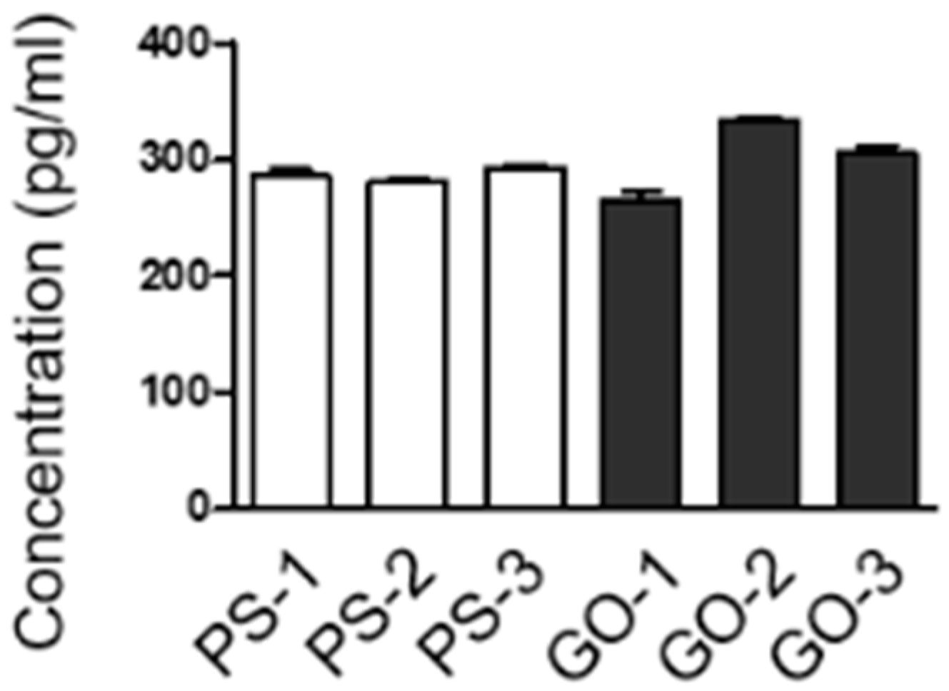
To compare the protein secretion of hBM-MSCs cultivated on PS or GO substrates, the protein expression of vascular endothelial growth factor (VEGF), which is known to be secreted in large amounts from hBM-MSCs, was investigated. The concentration of secreted VEGF from PS or GO substrates-cultured hBM-MSCs did not appear to have a significant difference (Figure 12). This also proves the MSC-specific characteristics of hBM-MSCs cultured on GO substrates.

4. Discussion

This study evaluated the mechanical properties of GO spray-coated onto the surface of a large-area polystyrene film. The possibility of developing a large-area cell culture vessel was analyzed by evaluating cell compatibility and cell proliferation on the GO-coated surface.
Step difference measurements across the GO-coated polystyrene film revealed a curve of 100 nm or higher on the film surface. The change in the flexural difference according to the number of coatings became more pronounced as the coating speed decreased. In general, the roughness values (Ra, Rq) of the entire surface reduced with increases in coating speed and increased with increases in the number of coatings. In particular, the difference in the average size of the surface curvature was large in the group coated at a low speed. In the case of medium speed (M group), the average size of surface curves similar to that of the low speed group (L group) appeared, but the number of surface curves was higher. Therefore, the magnitudes of the surface roughness and the number of curves can be controlled by appropriately adjusting the speed of the coating application. In the case of cells, it is known that cells adhere well to a curved surface rather than a flat surface during the cell adhesion process, and growth is good on a curved surface in the cell growth field [25]. In this study, an appropriate shape of the GO coating on the polystyrene surface appeared to facilitate cell growth. The G peak in the Raman spectra of all groups confirmed the GO coating, and the ID/IG ratios (0.88–0.94) confirmed the same type of GO with similar structural defects in each group. The transmittances of GO-coated surfaces (relative to that of uncoated polystyrene film) decreased as the number of coatings increased and the coating speed decreased. The contact angle measurements of the surface of the GO-coated polystyrene film confirmed a hydrophilic surface with higher surface energy than the hydrophobic polystyrene surface. Moreover, the cells better adhered to and proliferated on the hydrophilic surface provided by the GO coating [21].
The cells grew poorly on the uncoated polystyrene film but thrived on the GO-coated polystyrene film. After adhering to the surface, the cells increased in number and eventually formed colonies that flattened and extended across the surface. At this time, the surface energy and roughness ratio were appropriate for attachment and growth; however, when the number of coatings increased, the surface roughness became unfavorable which possibly explains the comparatively low cell adhesion rates on these surfaces [20,25,26]. As the cell proliferation rate was highest on the H3 sample, the cell culture efficiency was determined to be sufficiently increased by coating with small amounts of GO. As confirmed in the growth-rate analysis, the cell growth was enhanced by the surface roughness and hydrophilicity introduced by the GO coating, requiring no complex chemical treatment. Moreover, the polystyrene film inhibited cell growth, but the GO-coated polystyrene film was entirely nontoxic, thus confirming its improved cell compatibility.
Among the coating conditions set in this study, the smallest amount of GO (three coatings) deposited at the highest speed (93.25 mm/s) achieved the highest cell proliferation, indicating that a small amount of GO sufficiently increases the cell culturing efficiency. The cell viability on the H3 coating was 1.43 times higher than in the conventional cell culture vessel. That is, by optimizing the GO coating, we can realize an economical and practical large-area cell culture vessel that can maximize the cell culture efficiency.
In this study, we demonstrated that graphene oxide improved cell proliferation efficiencies and does not have cytotoxicity. Additionally, it was confirmed that the specific surface antigen expression of mesenchymal stem cells did not change. These findings demonstrate that the substrates based on graphene oxide are suitable and biocompatible for anchorage-dependent cell growth. Therefore, these substrates could be suggested for improved biological applications.

5. Conclusions

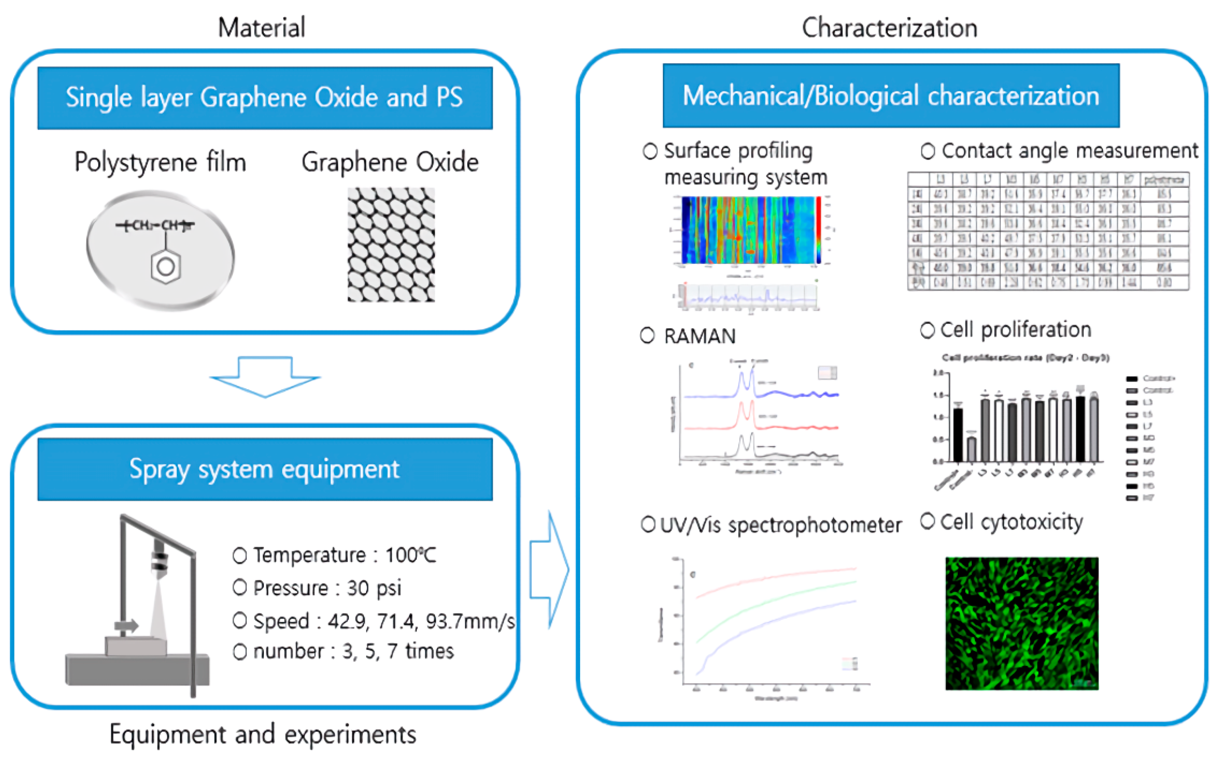
In this study, GO was spray-coated onto the surface of a large-area polystyrene film. The mechanical properties, cell compatibility, and cell proliferation on the GO-coated surface were evaluated to confirm the possibility of developing a large-area cell culture vessel (Figure 13). Through various biological analyses, the cell culture efficiency was found to be greatly improved by applying a simple spray-coating of GO onto conventional cell culture plates. The coating stability on the large scale area was also proved. These results supported the potential of GO as a promising biomaterial for the easy processing and functionalization of plastic surfaces.

Author Contributions

Conceptualization, J.-O.L. and J.-S.H.; investigation, D.-b.P., J.-h.L., S.-j.Y., J.-K.P., J.-e.L. and J.-b.P.; writing—original draft preparation, J.-b.P.; writing—review and editing, D.-b.P. and J.-O.L.; supervision, J.-O.L. and J.-S.H. All authors have read and agreed to the published version of the manuscript.

Funding

This work was supported by the National Research Foundation of Korea (NRF) grant funded by the Korean government (MSIT) (No. NRF-2021R1A5A8033165) and the Central Research Center, Corestem Inc. (Seoul, Republic of Korea).

Conflicts of Interest

The authors declare no conflict of interest.

References

  1. Zhu, Y.; Murali, S.; Cai, W.; Li, X.; Suk, J.W.; Potts, J.R.; Ruoff, R.S. Graphene and graphene oxide: Synthesis, properties, and applications. Adv. Mater. 2010, 22, 3906–3924. [Google Scholar] [CrossRef] [PubMed]
  2. Lui, C.H.; Liu, L.; Mak, K.F.; Flynn, G.W.; Heinz, T.F. Ultraflat graphene. Nature 2009, 462, 339–341. [Google Scholar] [CrossRef] [PubMed]
  3. Ovid’Ko, I.A. Mechanical properties of graphene. Rev. Adv. Mater. Sci. 2013, 34, 1–11. [Google Scholar]
  4. Han, J.T.; Jeong, S.Y.; Jeong, H.J.; Lee, G.W. Preparation of chemically exfoliated graphene nanosheets and its applications. KIC News 2012, 15, 23–37. [Google Scholar]
  5. Dreyer, D.R.; Park, S.; Bielawski, C.W.; Ruoff, R.S. The chemistry of graphene oxide. Chem. Soc. Rev. 2010, 39, 228–240. [Google Scholar] [CrossRef] [PubMed]
  6. Mkhoyan, K.A.; Contryman, A.W.; Silcox, J.; Stewart, D.A.; Eda, G.; Mattevi, C.; Miller, S.; Chhowalla, M. Atomic and electronic structure of graphene-oxide. Nano Lett. 2009, 9, 1058–1063. [Google Scholar] [CrossRef] [Green Version]
  7. Ma, W.S.; Li, J.; Zhao, X.S. Improving the thermal and mechanical properties of silicone polymer by incorporating functionalized graphene oxide. J. Mater. Sci. 2013, 48, 5287–5294. [Google Scholar] [CrossRef]
  8. Han, Z.Y.; Huang, L.J.; Qu, H.J. A review of performance improvement strategies for graphene oxide-based and graphene-based membranes in water treatment. J. Mater. Sci. 2021, 56, 9545–9574. [Google Scholar] [CrossRef]
  9. Hu, J.; Jia, X.; Li, C.; Ma, Z.; Zhang, G.; Sheng, W.; Zhang, X.; Wei, Z. Effect of interfacial interaction between graphene oxide derivatives and poly (vinyl chloride) upon the mechanical properties of their nanocomposites. J. Mater. Sci. 2014, 49, 2943–2951. [Google Scholar] [CrossRef]
  10. Politano, G.G.; Versace, C. Electrical and Optical Characterization of Graphene Oxide and Reduced Graphene Oxide Thin Films. Crystals 2022, 12, 1312. [Google Scholar] [CrossRef]
  11. Park, S. History of graphene oxide and future direction. KIC News 2013, 16, 1–5. [Google Scholar]
  12. Girão, A.F.; Serrano, M.C.; Completo, A.; Marques, P.A. Do biomedical engineers dream of graphene sheets? Biomater. Sci. 2019, 7, 1228–1239. [Google Scholar] [CrossRef]
  13. Palmieri, V.; Papi, M.J.N.T. Can graphene take part in the fight against COVID-19? Nano Today 2020, 33, 100883. [Google Scholar] [CrossRef]
  14. Raghav, P.K.; Mohanty, S. Are graphene and graphene-derived products capable of preventing COVID-19 infection? Med. Hypotheses 2020, 144, 110031. [Google Scholar]
  15. Kim, S.J.; Choi, Y.Y.; Lee, W.J.; Kim, K.B. Fabrication Parameter-Dependent Physico-Chemical Properties of hiolated Gelatin/PEGDA Interpenetrating Network Hydrogels. Tissue Eng. Regen. Med. 2021, 19, 309–319. [Google Scholar] [CrossRef]
  16. Christopherson, G.T.; de Vasconcellos, J.F.; John, C.; Griffin, D.W.; Jones, P.E.; Nesti, L.J. Three-Dimensional Modeling of the Structural Microenvironment in Post-Traumatic War Wounds. Tissue Eng. Regen. Med. 2021, 18, 963–973. [Google Scholar] [CrossRef]
  17. Park, D.B.; Park, J.B.; Lee, J.H.; Shim, C.J.; Kim, M.S.; Lee, T.Y.; Lim, J.O. Fabrication and Characterization of Graphene Oxide-Coated Plate for Efficient Culture of Stem Cells. Tissue Eng. Regen. Med. 2021, 18, 775–785. [Google Scholar] [CrossRef]
  18. Park, J.B.; Lee, J.H.; Huh, J.S.; Park, D.B.; Lim, J.O. Investigation on the polystyrene surface coating method of graphene oxide. J. Korean Inst. Surf. Eng. 2021, 54, 77–83. [Google Scholar]
  19. Lee, J.H.; Park, J.B.; Park, D.B.; Huh, J.S.; Lim, J.O. Coating properties of single and multi-layer graphene oxide on a polystyrene surface. Korean J. Mater. Res. 2021, 31, 420–426. [Google Scholar] [CrossRef]
  20. Groth, T.; Altankov, G. Studies on cell-biomaterial interaction: Role of tyrosine phosphorylation during fibroblast spreading on surfaces varying in wettability. Biomaterials 1996, 17, 1227–1234. [Google Scholar] [CrossRef]
  21. Jo, D.A.; Song, K.S. Cell count sensor using graphene FET. J. Inst. Electron. Inf. Eng. 2021, 58, 71–76. [Google Scholar]
  22. Horbett, T.A. The role of adsorbed proteins in animal cell adhesion. Colloids Surf. B Biointerfaces 1994, 2, 225–240. [Google Scholar] [CrossRef]
  23. Tamada, Y.; Ikada, Y. Cell adhesion to plasma-treated polymer surfaces. Polymer 1993, 34, 2208–2212. [Google Scholar] [CrossRef]
  24. Skarlatos, S.I.; Rao, R.; Kruth, H.S. Accelerated development of human monocyte-macrophages cultured on Plastek-C tissue culture dishes. J. Tissue Cult. Methods 1992, 14, 113–117. [Google Scholar] [CrossRef]
  25. Hong, J.W.; Shin, J.H. Effects of surface geometrical properties on cellular adhesion behavior. In Proceedings of the Korean Society of Mechanical Engineers, Lectures and Abstracts, Fall Conference, Pyeong Chang, Korea, 4–11 November 2009; pp. 2963–2966. [Google Scholar]
  26. Majhy, B.; Priyadarshini, P.; Sen, A.K. Effect of surface energy and roughness on cell adhesion and growth–facile surface modification for enhanced cell culture. RSC Adv. 2021, 11, 15467–15476. [Google Scholar] [CrossRef]
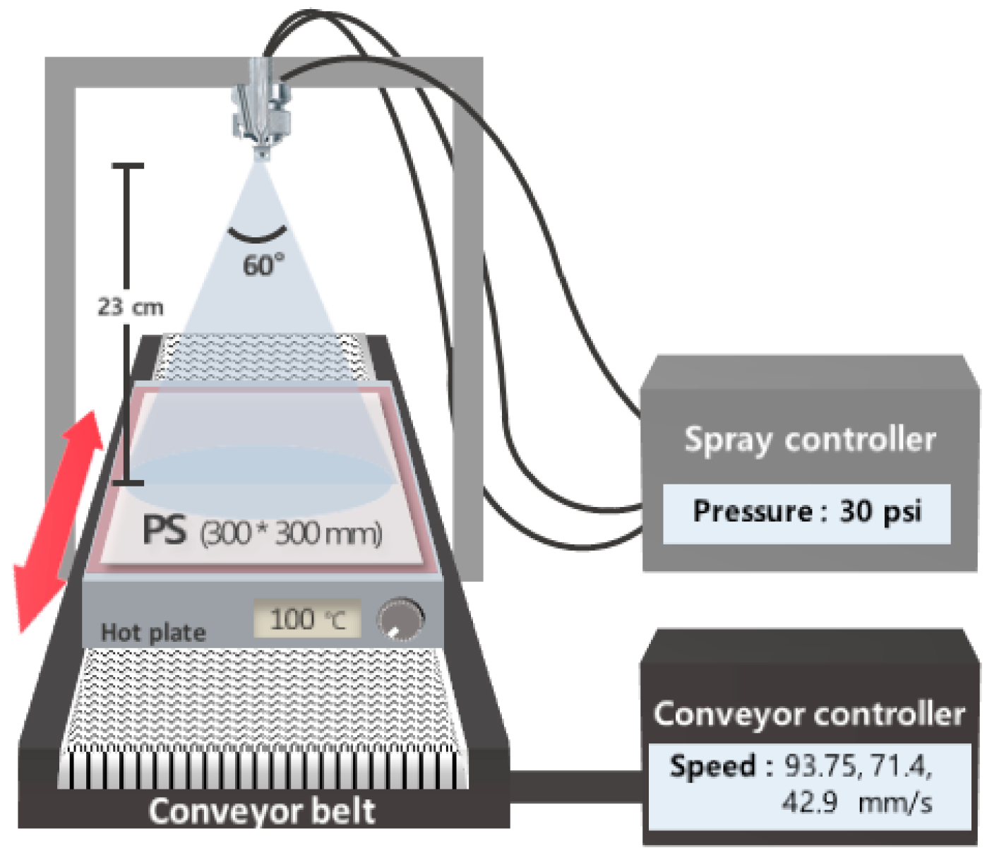
Figure 1. Schematic of large-area spray coating.
Applsci 12 11599 g001
Figure 2. Preparation of a cell culture slide coated with a GO-coated polystyrene film.
Applsci 12 11599 g002
Figure 3. Step measurement images of L3, L5, and L7 (top row), M3, M5, and M7 (middle row), and H3, H5, and H7 (bottom row). Compared to the center line, the average surface curvature is largest in the L group, and the number of curvatures is highest in the M group. The average roughness values were ~70–450 nm in the L group, 110–150 nm in the M group, and 100–150 nm in the H group. In the slow L group, the number of coatings remarkably affected the average roughness.
Applsci 12 11599 g003
Figure 4. Raman spectra of the L, M, and H groups. The G peak in all groups is the characteristic peak of graphene oxide (GO). The ID/IG values range from 0.88 to 0.94, indicating similar defects.
Applsci 12 11599 g004
Figure 5. Transmittance spectra of the L, M, and H groups. The transmittance is highest in the H group and in the films with three coatings in any group.
Applsci 12 11599 g005
Figure 6. Schematic diagram of contact angle measurement. This is the contact angle between the polystyrene cell culture plate and the GO-coated polystyrene cell culture plate (the sample showing the best cell growth). The contact angle of PS was measured to be 85.6°, and that of H3 was measured to be 54.6°.
Applsci 12 11599 g006
Figure 7. OD values of cells on the control slides and the GO-coated film, analyzed by the CCK-8 assay: (a) OD values measured on Days 2 and 3 (n = 3). The cells significantly proliferated on the positive control and GO-coated film. The cell growths (OD values) on both days were highest in the H3 sample. Data are presented as the means ± SDs, * p < 0.05, ** p < 0.01, *** p < 0.001, **** p < 0.0001 vs. day 2. (b) Cell proliferation rates analyzed by comparing the OD values on Days 2 and 3 (n = 3): control+ = 123.03%, control- = 58.76%, A1 = 141.43%, A2 = 140.54%, A3 = 131.10%, B1 = 141.23%, B2 = 139.18%, B3 = 143.11%, C1 = 141.62%, C2 = 146.69%, C3 = 144.28%, analyzed. Data are presented as the means ± SDs, * p < 0.05, ** p < 0.01, *** p < 0.001. **** p < 0.0001 vs. positive control; #### p < 0.0001 versus negative control.
Applsci 12 11599 g007
Figure 8. Comparison of OD on the 3rd day and roughness values in the L group (a) and H group (b) The surface roughness values of the GO-coated polystyrene films tended to increase with the number of coatings.
Applsci 12 11599 g008
Figure 9. Live/dead cell assay images obtained under a fluorescent microscope (combining a green and red filter). Cells adhered and proliferated on the GO coated on polystyrene film, confirming zero cytotoxicity.
Applsci 12 11599 g009
Figure 10. Morphology and cell proliferation of hBM-MSCs on PS and GO substrates. Morphology of hBM-MSCs on PS and GO substrates (a) Cell viability of hBM-MSCs (b) Population doubling level and population doubling time of hBM-MSCs (c) Growth of cells increased by about 27% in cells of GO substrates compared to PS substrates. Data are presented as the means ± SDs, ** p < 0.01, *** p < 0.001 versus control (PS).
Applsci 12 11599 g010
Figure 11. Flow cytometric analysis of MSC markers. The expression of MSC positive markers was all over 95% and of MSC negative markers was less than 1%.
Applsci 12 11599 g011
Figure 12. Secretion of a cytokine. The concentration of secreted VEGF from PS or GO substrates-cultured hBM-MSCs did not appear to have a significant difference.
Applsci 12 11599 g012
Figure 13. Schematic of the experiment.
Applsci 12 11599 g013
Table 1. Coating conditions.
Speed42.90 mm/s71.40 mm/s93.75 mm/s
Time
3L3M3H3
5L5M5H5
7L7M7H7
L: Low speed at 42.90 mm/s, M: Medium speed at 71.40 mm/s, H: High speed at 93.75 mm/s. 3: 3 times coatings, 5: 5 times coating, 7: 7 times coating.
Table 2. Average step differences across the samples.
L3L5L7M3M5M7H3H5H7
Ra a (nm)732104581521181419398148
Rq b (nm)98262521193166183124125181
a average roughness. b root-mean-square.
Table 3. Water contact angles of the L, M, and H surfaces. (PS = polystyrene) The measurement results are expressed as average values after 5 measurements.
L3L5L7M3M5M7H3H5H7PS
Average40.039.039.851.036.638.454.636.236.085.6
deviation0.460.510.692.280.620.751.730.990.440.80
Publisher’s Note: MDPI stays neutral with regard to jurisdictional claims in published maps and institutional affiliations.