Article

An Improved Surface Treatment Process of 304 Stainless Steel Based on Low-Temperature Chromizing and Ultrasonic Vibration Extrusion

1
School of Mechanical Engineering and Automation, Beihang University, Beijing 100191, China
2
Beijing Xinfeng Aerospace Equipment Co., Ltd., Beijing 100854, China
3
Institute of Artificial Intelligence, Beihang University, Beijing 100191, China
4
MIIT Key Laboratory of Intelligent Manufacturing Technology for Aeronautics Advanced Equipments, Ministry of Industry and Information Technology, Beijing 100191, China
*
Author to whom correspondence should be addressed.
Appl. Sci. 2022, 12(22), 11729; https://doi.org/10.3390/app122211729
Submission received: 19 September 2022 / Revised: 7 November 2022 / Accepted: 16 November 2022 / Published: 18 November 2022

Abstract

:
The ultrasonic vibration extrusion process is a widely used surface treatment process of stainless steel, e.g., 304 stainless steel, to improve the surface quality and increase hardness and wear resistance. However, for high-hardness 304 stainless steel, the traditional process, i.e., a single ultrasonic vibration extrusion process, does not fulfil its application requirements. To cope with this problem, this paper proposes an improved surface treatment method based on low-temperature chromizing and ultrasonic vibration extrusion to obtain the expected surface quality of 304 stainless steel. Using orthogonal design and multivariate regression, the influence of ultrasonic impact parameters on the surface integrity of 304 stainless steel was studied in this work. Finally, the experimental results show that the hardness of the surface processed by the proposed method is increased by about 2.55 times compared with the ultrasonic vibration extrusion process, and the surface roughness of the composite process is reduced by an average of 60.8% compared with that of unfinished surface. In addition, the optimal combination of process parameters is obtained: the spindle speed of 240 rpm, the feed of 0.1 mm/r, and the static extrusion of 40 μm, which can provide the optimal process parameter support for the surface treatment of 304 stainless steel.

1. Introduction

Stainless steel has proved to be a vital material found in modern industries, e.g., energy, chemical industry, and aviation due to its excellent properties, e.g., high strength, weldability, corrosion resistance, easy processing, and surface gloss [1,2,3,4,5,6]. There has been high demand for 304 stainless steel with high strength, hardness, precision, wear resistance and corrosion resistance. Currently, the surface modification process mainly includes ultrasonic shot peening, ultrasonic rolling, surface film strengthening and heat treatment strengthening technology (e.g., carburizing and nitriding) [7,8].
Ultrasonic extrusion is used for surface treatment as a hybrid treating process combining conventional extrusion and ultrasonic vibration, which converts electric power into mechanical vibration at the ultrasonic frequency [9]. The chromizing treatment is a chemical surface heat treatment process in which chromium is infiltrated into the surface of metal parts [10]. In the mid-19th century, Blaha et al. [11] proposed the effect of ultrasonic excitation on the elastic–plastic deformation of the metal. A group of scholars [12,13,14,15] studied the metal wire drawing and extrusion technology by adding ultrasonic vibration, performed complex operations and processing of the metal under different conditions, and analyzed the results by using the finite element method, which shows that the ultrasonic vibration has advantages such as reducing the coefficient of friction and the cutting force. Bozdana et al. [16,17] then studied the ultrasonic impact surface strengthening of metal materials, which shows that only a tiny static extrusion pressure was required to produce plastic deformation on the metal surface when the ultrasonic impact was superimposed. Dong et al. [18] focused on the chromizing of 316L stainless steel, which shows that the corrosion resistance of the stainless steel is significantly improved by chromizing. Ruan et al. [19] performed chromizing strengthening treatment on the surface of titanium alloy, showing that chromizing treatment significantly improves the fatigue resistance of the specimen. Wang et al. [20] conducted ultrasonic impact research on 65 Mn steel after chromizing treatment, which shows that ultrasonic impact strengthens the chromizing layer and enhances the wear resistance of the stainless steel. Dong [21] studied the chromizing surface modification technology of 316L stainless steel, which indicates that chromizing surface modification significantly improves the corrosion resistance of the stainless steel.
Most of the above papers only studied a single surface treatment process. For example, many researchers are studying ultrasonic vibration-assisted machining as a special machining method, with its own machining characteristics and advantages. However, a single process is difficult to meet the actual machining needs at the same time. For example, in this paper, the single ultrasonic vibration-assisted machining can only meet the roughness requirements and cannot meet the hardness requirements. In addition, the traditional chromizing process has some practical problems. The high temperature of traditional chromizing treatment causes obvious deformation of low-temperature alloy workpieces, coarsening of workpiece grain structure and deterioration of working performance.
Thus, to solve the problems above, a low-temperature chromizing–ultrasonic extrusion composite surface modification process (composite process) is introduced to make 304 stainless steels achieve better surface properties that combine the advantages of two processes such as high residual compressive stress, hardness and wear resistance while obtaining low surface roughness [22,23].
The composite process can eliminate the limitations of a single process and reach multiple requirements in practice such as high hardness and low surface roughness. In addition, low-temperature chromizing treatment reduces the effect of temperature on the change of grain structure, thus the stability of material properties is improved, e.g., the surface hardness, corrosion resistance, oxidation resistance and surface wear resistance of parts.
In this work, the influence of the spindle speed, feed and static extrusion on surface properties, e.g., surface hardness, surface roughness and surface morphology, is focused on optimizing the process parameters for the proposed method. Through the orthogonal design results of three factors including feed rate, spindle speed and static extrusion amount, the order of influencing factors and the best process parameters were obtained. Meanwhile, the roughness and hardness models were obtained through multiple regression analysis. In addition, the feasibility of the proposed method is verified by comparing the low-temperature chromizing, ultrasonic extrusion, and low-temperature chromizing–ultrasonic extrusion composite surface modification processes.

2. Improved Surface Treatment Process Based on Low-Temperature Chromizing and Ultrasonic Vibration Extrusion

2.1. Low-Temperature Chromizing Process

The treatment temperature of the traditional chromizing method is generally higher than 1000 °C for about 6 h. In the process of long-time high-temperature chromizing, the grain of the infiltrated workpiece often grows, resulting in the decline of the mechanical properties of the infiltrated workpiece, which limits the wide application of chromizing technology. This paper adopts the method of low-temperature salt bath chromizing treatment to realize the chromizing treatment of 304 stainless steel at 700 °C. The specific process includes the following steps:
  • Sodium salt or potassium salt is selected as the primary solvent, and low melting point chromium salt is used as the auxiliary agent.
  • Chromium powder or ferrochromium powder is used as the chromizing agent.
  • The workpiece to be infiltrated, one of sodium salt or potassium salt, chromium salt and chromium powder or ferrochromium powder infiltrating agent are put in a closed container.
  • The temperature is raised to a specific temperature which is kept for a particular time.
  • Hydrogen is continuously injected into the closed container under a certain pressure during the insulation process.
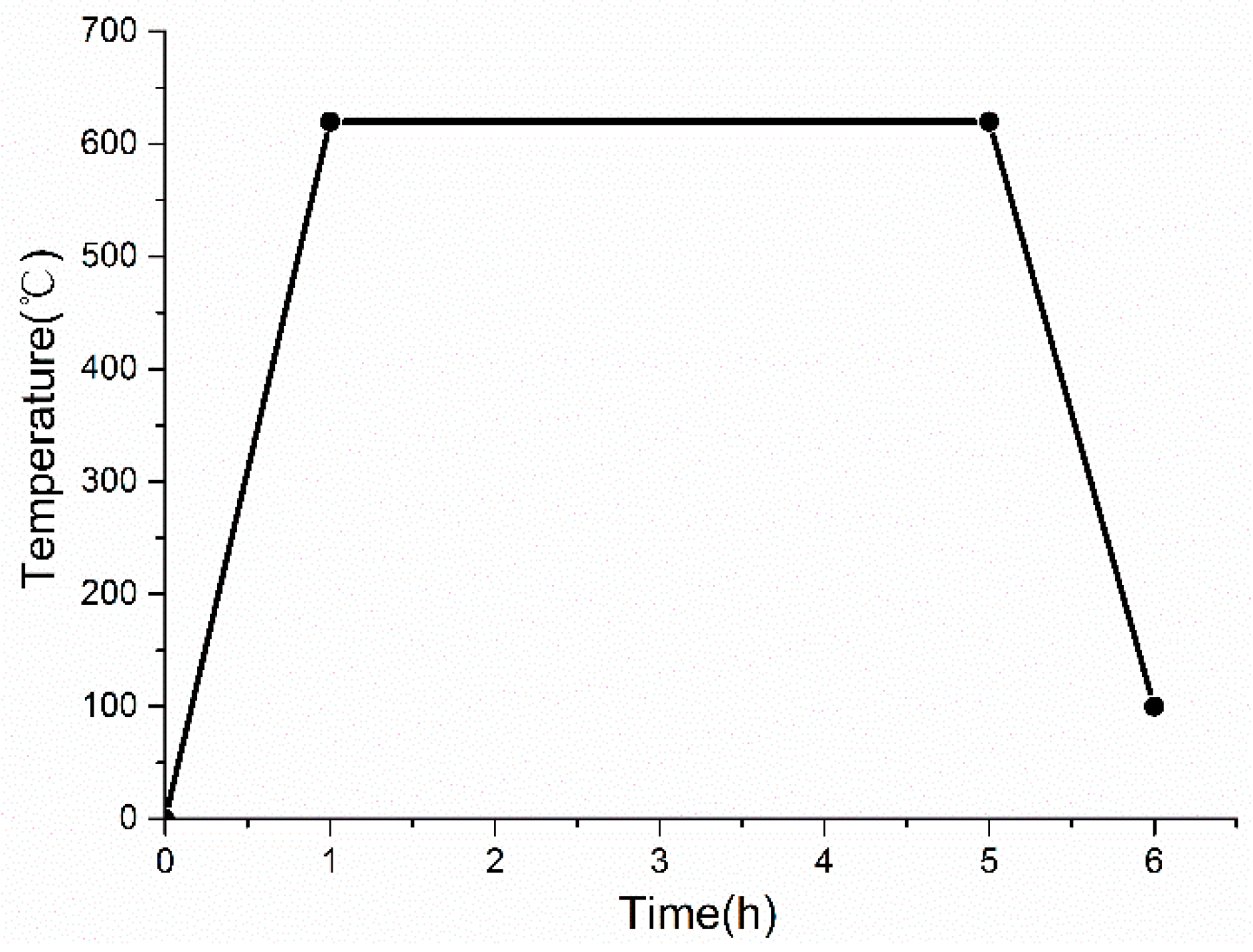
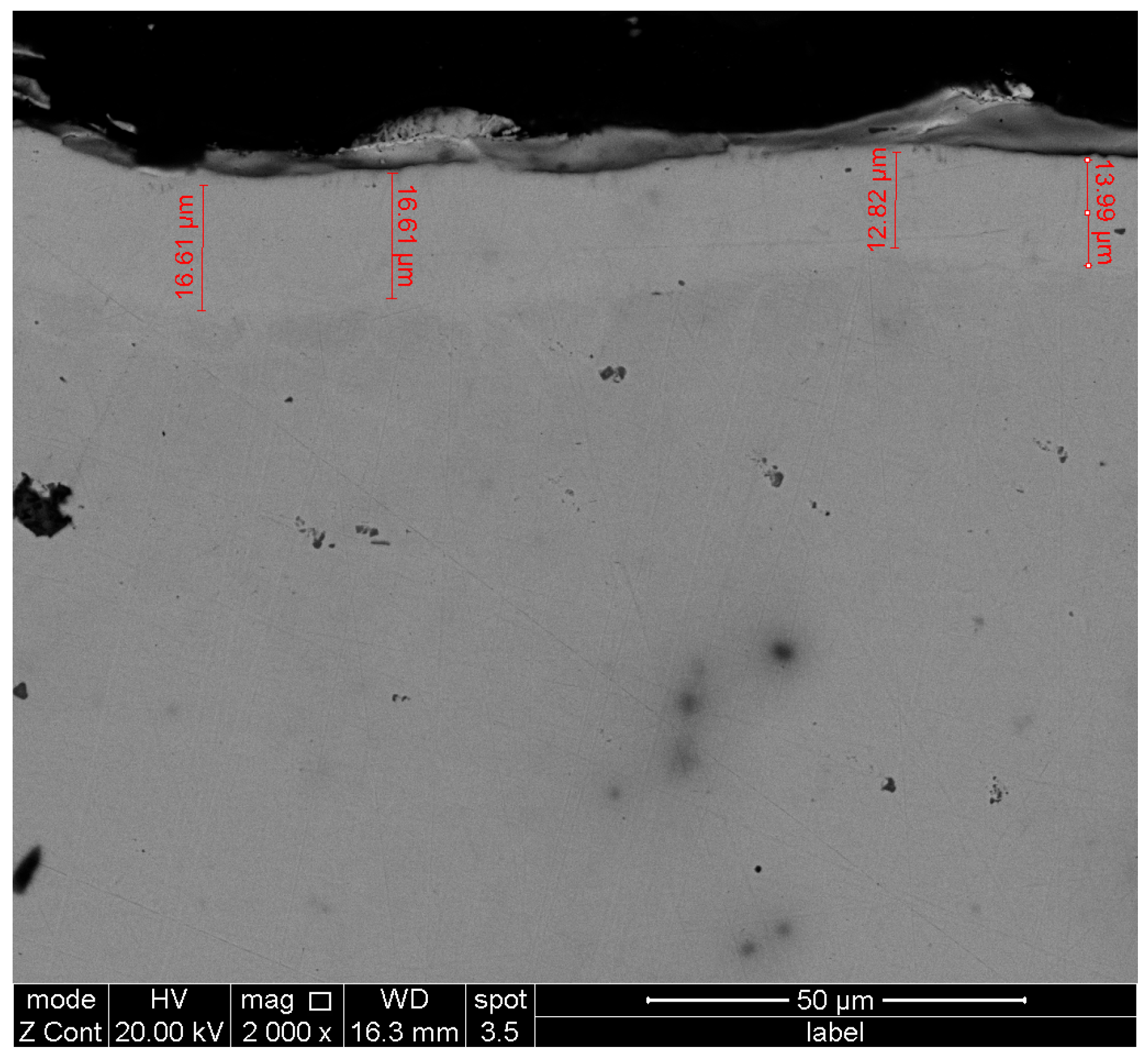
The solvents are NaCl and CrCl3 · 6H2O, where the weight proportion of CrCl3 · 6H2O is 25%. Chromium powder is added, and the weight ratio of chromium powder to CrCl3 · 6H2O is 1:6. Those materials are mixed and then poured into a crucible and loaded with the 304 stainless steel parts. The crucible is placed into a closed container with a vacuum and starts to heat up. After the temperature rises to 620 °C, hydrogen is slowly injected into the container. When the hydrogen pressure is higher than 0.02 MPa, injection of hydrogen is stopped, and the temperature is kept for 4 h. During the insulation process, if the pressure is lower than 0.02 MPa, the hydrogen is continuously injected until the pressure is higher than 0.02 MPa. It is then cooled to within 100 °C and taken out the workpiece. The principle of chromizing process is shown in Figure 1. The chromizing temperature curve is shown in Figure 2. After taking out the workpiece, dehydrogenation treatment is conducted at 200 °C for 4 h. The obtained chromizing layer is 10~20 μm, as shown in Figure 3.
In the above processes, the melting point of NaCl is 801 °C, and the melting point of CrCl3 · 6H2O is 83 °C. After the two are mixed in a certain proportion, the melting point of the mixture can be controlled below 650 °C. Under the condition of hydrogen, the following reactions are occurred by
2CrCl3 + H2 = 2CrCl2 + 2HCl,
CrCl2 + Fe = FeCl2 + [Cr],
CrCl2 + H2 = 2HCl + [Cr].
Thus, it can be observed that the active chromium atoms produced by Reactions (2) and (3) penetrate into the surface of 304 stainless steel, and the thickness of the chromized layer is also increased with the reaction progress.

2.2. Ultrasonic Vibration Extrusion Process

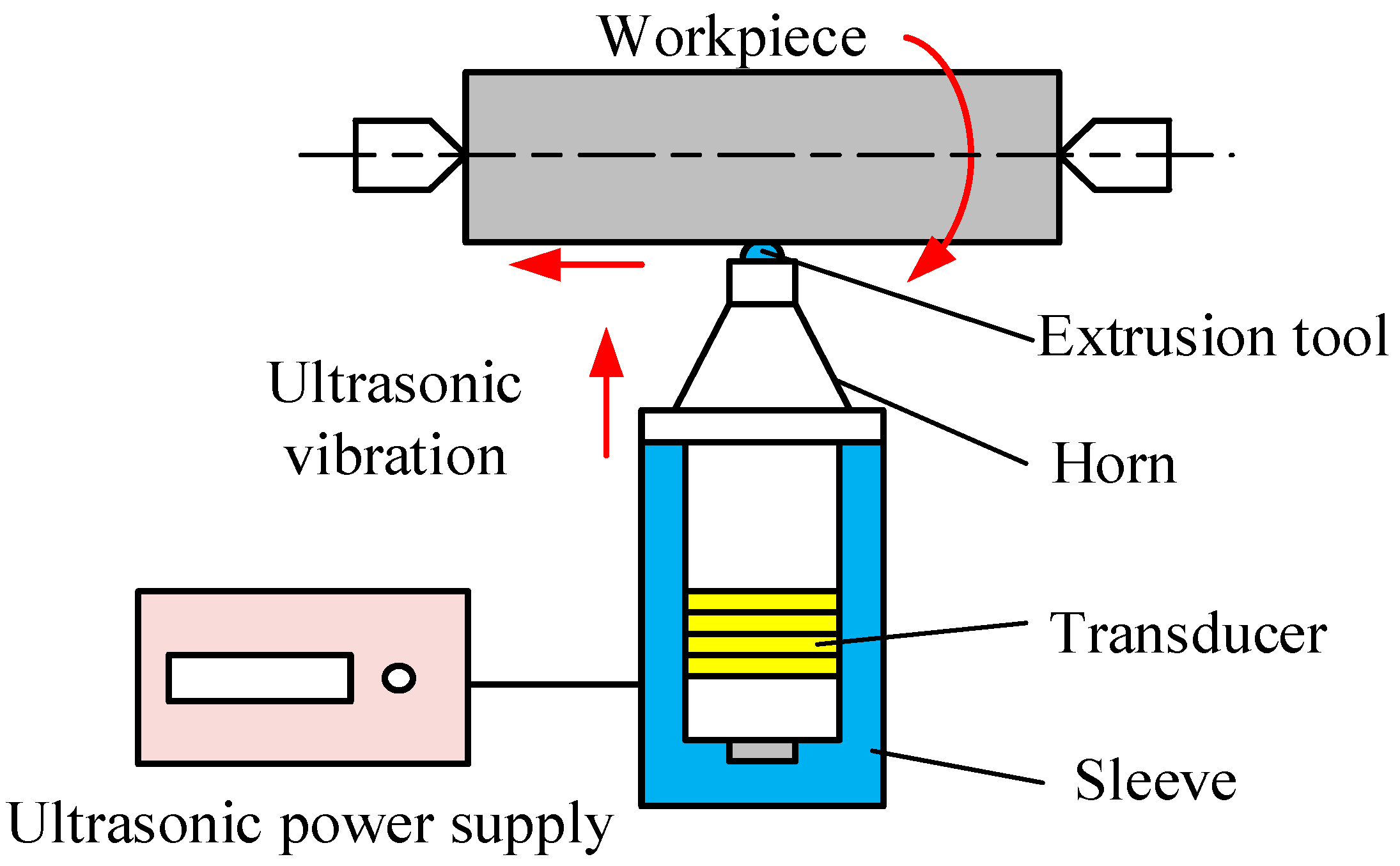
The ultrasonic vibration extrusion system is mainly composed of an ultrasonic power supply, transducer, horn, extrusion tool and sleeve [24] as shown in Figure 4.
The AC power is converted into electrical oscillation at the resonance frequency of the transducer by the ultrasonic generator. The electrical oscillation is converted into longitudinal mechanical vibration at the same frequency by the transducer. The vibration is then transferred to the tool through the horn, which has an increased amplitude.
The mechanical vibration, predominantly longitudinal mechanical vibration, is amplified by the horn and transferred to the extrusion tool. With ultrasonic vibration, the tool impacts the workpiece at a high frequency; then, the machined surface of the workpiece and the extrusion tool head displays micro separation with the machined surface, leading to better surface properties [25], e.g., lower surface roughness and higher residual compressive stress. Thus, the ultrasonic extrusion process has been used in the material surface strengthening treatment of hard brittle and difficult to machine and thin-walled cylindrical parts [26].

3. Experimental Setup

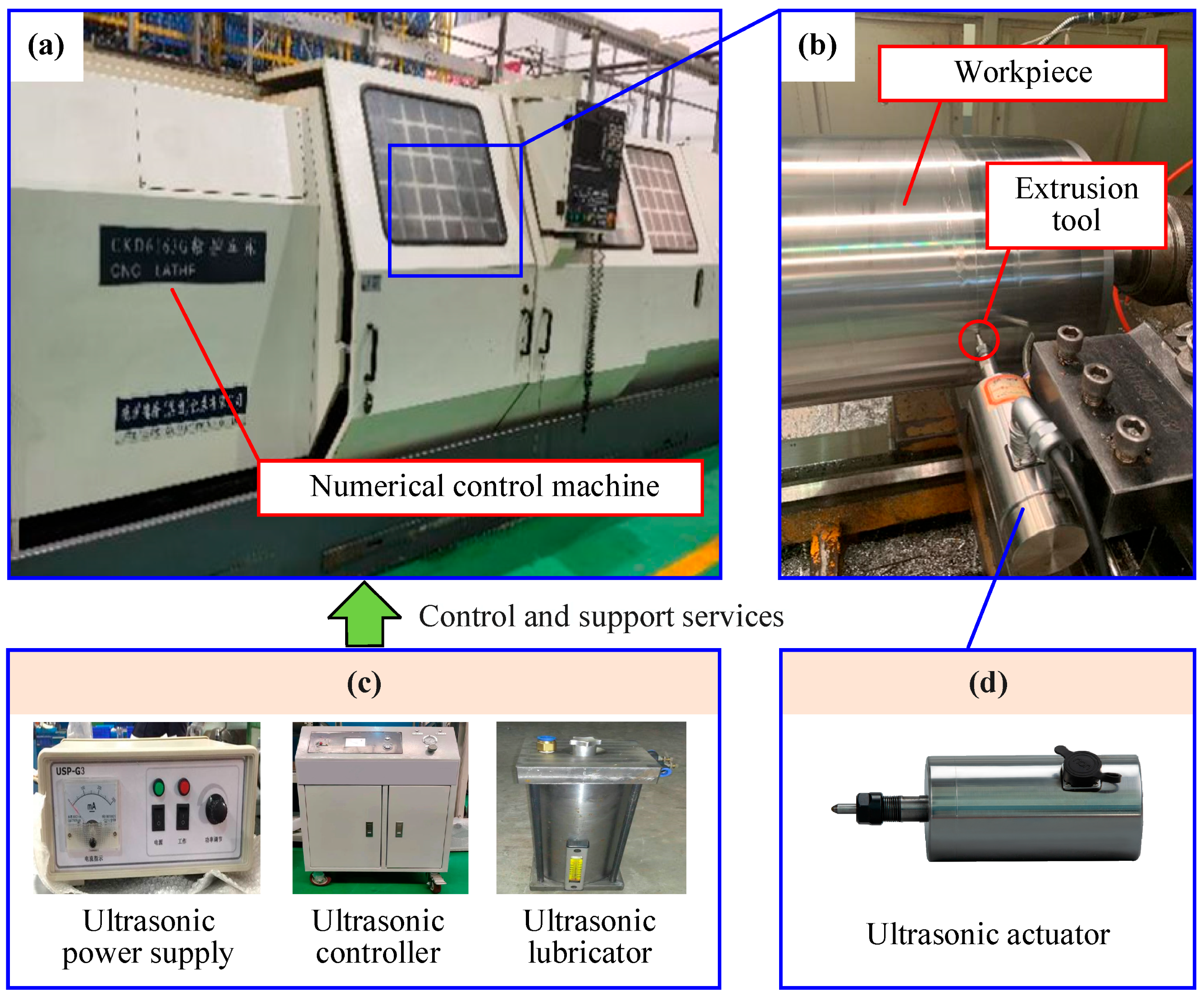
The experiment is carried out using the numerical control machine (CKD6163G) and ultrasonic vibration equipment, as indicated in Figure 5. Roughness meters, hardness testers, and scanning electron microscopes, respectively, are used to determine the surface roughness, hardness, and surface morphology. According to the operational instructions, the operating parameters of the ultrasonic vibration apparatus were set to a frequency of 41.243 kHz and an amplitude of 5 μm, respectively.

3.1. Principle of Ultrasonic Vibration Extrusion

The operating frequency is determined by the ultrasonic vibration device; it is the series resonant frequency or resonant frequency of the ultrasonic vibration device. The series resonant frequency and resonant frequency are the inherent properties of the ultrasonic vibration device, which can be detected by the ultrasonic power supply and displayed on the ultrasonic controller. The amplitude can reach 5 µm at 100% power according to the product manual, and 100% power was used in the experiment.
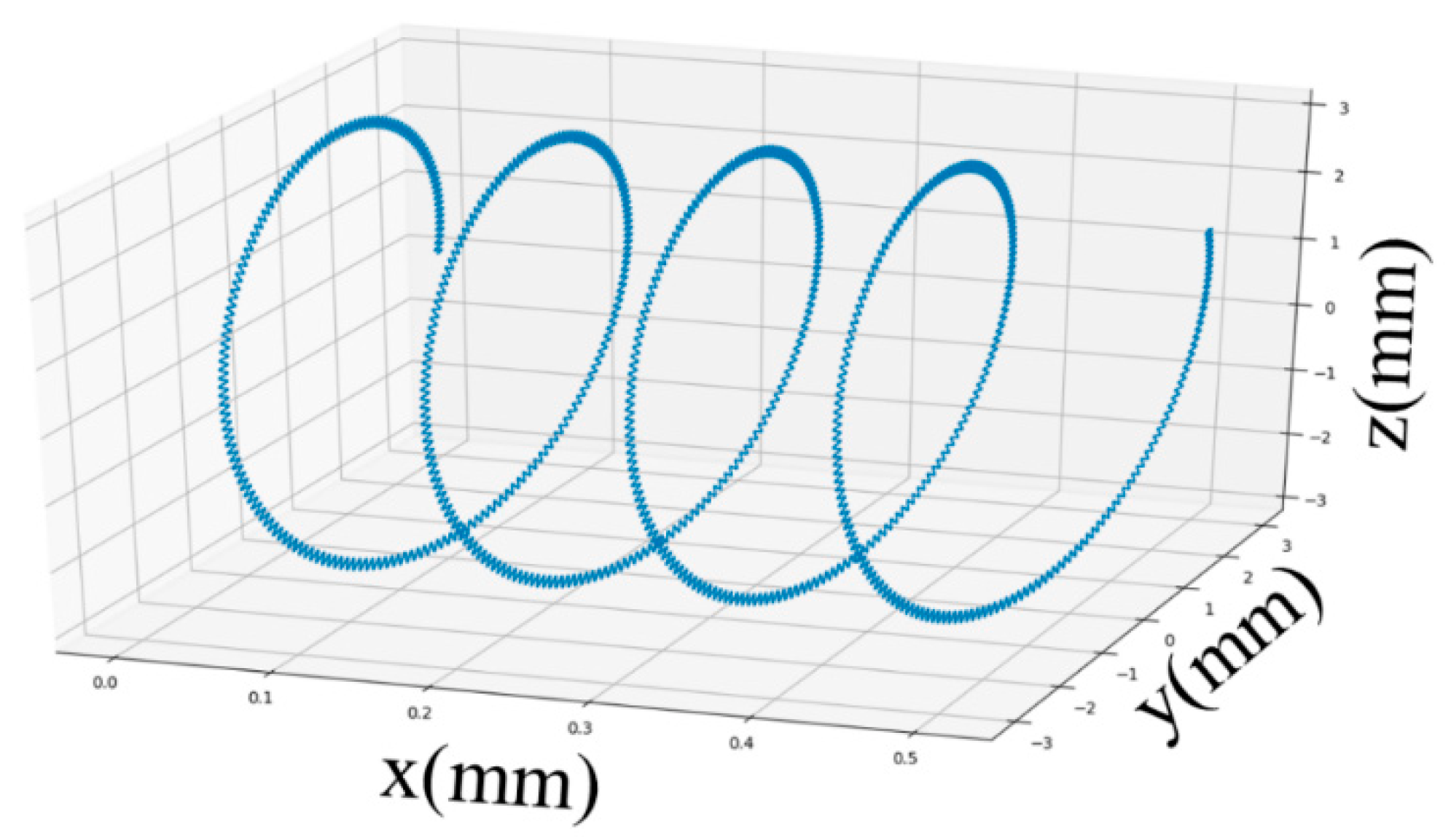
Ultrasonic vibration extrusion superimposes the longitudinal vibration at the ultrasonic frequency on the traditional extrusion, and the vibration magnitude is generally on the micrometer scale [27]. Assuming that the section which contains the current contact point of the tool and workpiece is perpendicular to the workpiece axis, the intersection of the axis and the section is the coordinate origin O, and the workpiece axis is the X axis. The positive Y direction is the feed direction of the tool, and the section is the YZ plane. The schematic diagram of the motion trajectory of the tooltip relative to the workpiece is shown in Figure 6.
Assuming that the ultrasonic vibration is sinusoidal and the workpiece is stationary, the tool moves along the workpiece surface in the form of spiral feed, accompanied by the sinusoidal ultrasonic vibration with the direction of motion pointing to the axis of the workpiece (i.e., x axis in Figure 6). In this case, the motion equation of the tip of the tool is given by [28]
x = v r = v n t y = r + A u t sin 2 π f t cos 2 π n t z = r + A u t sin 2 π f t sin 2 π n t ,
where v , n , r , A u t , f and t represent the feed, rotation speed, workpiece radius, ultrasonic amplitude, frequency, and time, respectively.
The operating frequency 41.243 kHz and ultrasonic amplitude 5 µm correspond to f and A u t in Formula (4). A larger operating frequency will cause the tool head to produce more hammering times, and a larger ultrasonic vibration amplitude will increase the hammering depth of the tool head, making it easier to produce plastic deformation on the machined surface.
With ultrasonic vibration of the tool, the high instantaneous strain rate and the high-frequency cyclic load of dynamic ultrasonic loading cause stress waves in the material. Take one period of the ultrasonic vibration loading cycles for analysis. When the tool vibrates forward, the material is in the loading stage, and the dislocations in the deformation region slide, multiply and plug up rapidly, leading the plastic deformation stress increases rapidly. At this time, the compressive stress wave is transmitted along the axial direction; when the punch vibrates backwards, the material is unloading, and the stress wave is emitted at the bottom of the material, transformed into a tensile stress wave, and then transmitted in the reverse direction. Thus, the transmission of the stress wave significantly changes the stress state in the deformation region, causing the internal structure of the material to slide in the reverse direction, and the dislocation also diffuses in multiple directions, significantly reducing the dislocation accumulation. At the same time, the dislocation moving in the opposite direction is easier to meet and annihilate, which can not only improve the plastic deformation limit of the material but also significantly reduce the deformation stress. After 41,243 loading cycles (i.e., the ultrasonic vibration frequency) in 1 s, the material undergoes significant plastic deformation under high-frequency dynamic loading and produces significant strengthening on the surface.

3.2. Experimental Design

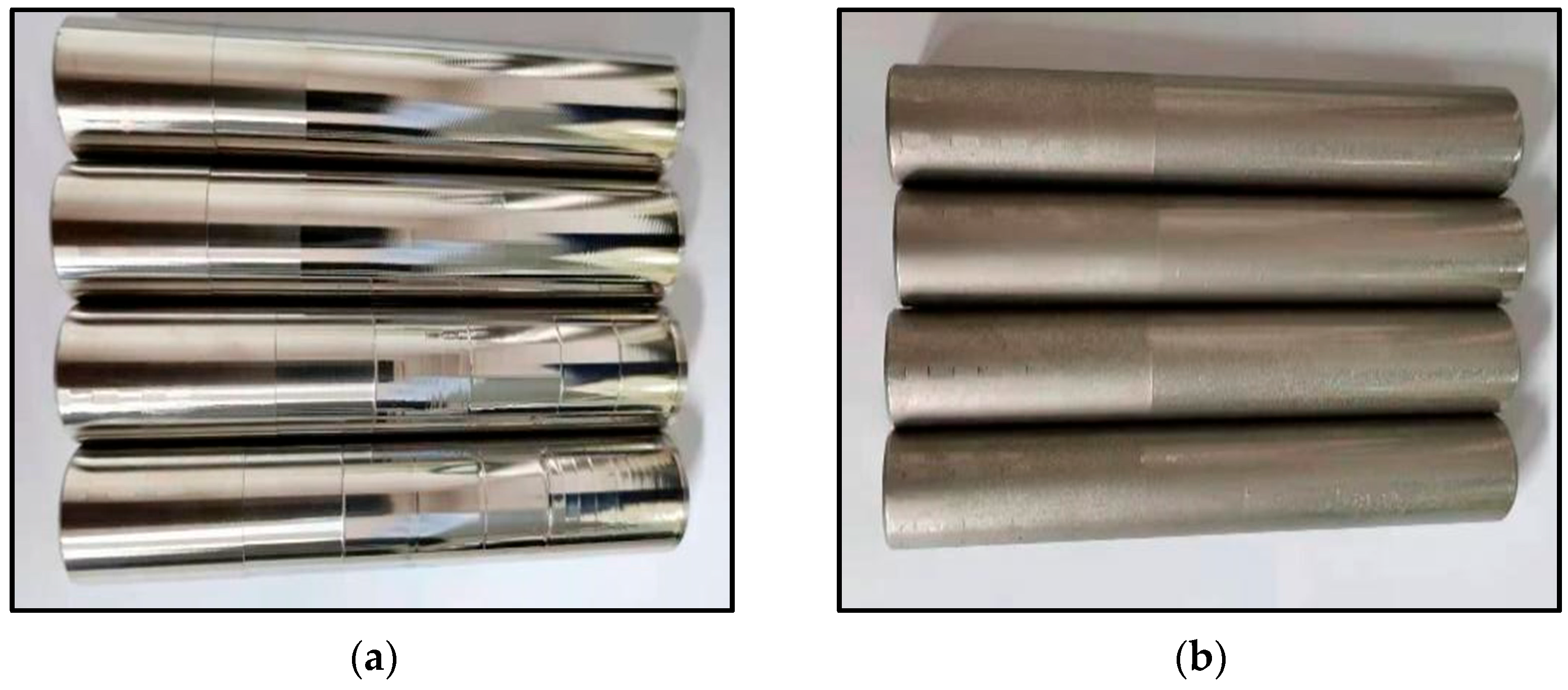
The 304 stainless steel sample was a 20 mm-diameter cylinder with a length of 100 mm. The samples after the composite treatment (i.e., the composite process combining the low-temperature chromizing treatment with the ultrasonic vibration extrusion treatment) are shown in Figure 7a,b, respectively.
The ultrasonic vibration equipment was clamped on the numerical control machine for the surface treatment of the sample workpiece. The tip radius of the diamond extrusion tool was 2 mm, and the main processing parameters were the spindle speed of n , the feed f of the extrusion tool and static extrusion amount P of tool head. The orthogonal test was conducted for these process parameters. Without considering the complexity of the interaction, a three-factor and four-level orthogonal tests were selected, and the test table is shown in Table 1.
The expected process parameter range is selected according to the processing efficiency and ultrasonic vibration processing effect. When the spindle speed is lower than 100 rpm, the feed speed (mm/min) decreases, resulting in low processing efficiency and long processing time. When the spindle speed is higher than 300 rpm, the feed speed increases and the processing time is shortened, resulting in the reduction of ultrasonic vibration hammering density on the machined surface, thus reducing the ultrasonic vibration processing effect. The effect of feed is consistent with the speed. When the feed is too high, the ultrasonic extrusion effect will be reduced, and when the feed is too small, the processing efficiency will be low. When the static extrusion amount is too small, the ultrasonic vibration hammering effect is weak, thus reducing the ultrasonic extrusion effect. When the static extrusion amount is too large, the removal amount will be generated, which will affect the machining dimensional accuracy. To sum up, the process parameters are selected as the spindle speed of 100–300 rpm, the feed of 0.04–0.1 mm/r, and the static extrusion amount of 10–40 μm.

4. Experimental Results and Discussion

4.1. Analysis of the Surface Roughness and Hardness

In this study, the experimental scheme of ultrasonic extrusion process based on L16 (34) was designed [29], as shown in Table 2. Ultrasonic extrusion tests were carried out in 32 groups, including 16 groups of composite process experiments and 16 groups of conventional ultrasonic vibration extrusion experiments.
The surface roughness Ra and hardness of 304 stainless steel substrates were 0.792 μm and 164.84 Hv before the experiments. The hardness is measured with a Vickers hardness tester (HVS-1000Z Vickers hardness tester). The applied loading force is 20 g and the holding time is 15 s. After unloading, the Vickers hardness value of the measured point is calculated by measuring the diagonal length of the diamond indentation. Jimtec TR200 surface roughness measuring instrument is used for surface roughness. For each experimental group, the surface roughness and hardness were measured five times along the circumferential direction and displayed the averaged value as the final result. Table 2 shows the test results of the composite process and ultrasonic extrusion process.
As shown in Table 2, the ultrasonic extrusion can effectively reduce the surface roughness and enhance the surface hardness of 304 stainless steel. The lowest surface roughness value and the highest surface hardness value are obtained at the spindle speed of 300 rpm, the feed of 0.04 mm/r and the static extrusion of 40 μm, which are 0.065 μm and 212.49 Hv, respectively. Compared with the 304 stainless steel substrates, the roughness underwent a substantial improvement, and the hardness has increased by about 28%.
The average value of processed surface hardness can reach 615 Hv, and the maximum can reach 754.15 Hv after the composite process. Compared with the initial substrate surface hardness (164 Hv), the surface hardness of 304 stainless steel increased by 2.75 times. The average surface roughness value is 0.310 μm, compared with the initial substrate surface roughness (0.792 μm) reduced by 60.86%, indicating that the composite process can effectively improve the surface hardness and reduce the surface roughness.
During the extrusion process, the extrusion tool head impacts the surface at the ultrasonic frequency and causes micro-separation while feeding along the workpiece axially at certain working parameters. The high-frequency energy is channeled into the material from the surface, causing the surface material of the extruded workpiece to be elastically and plastically deformed. The micro surface depression on the surface will be filled up by its plastic deformation after ultrasonic extrusion, causing the metal part to achieve a more desirable surface [30].
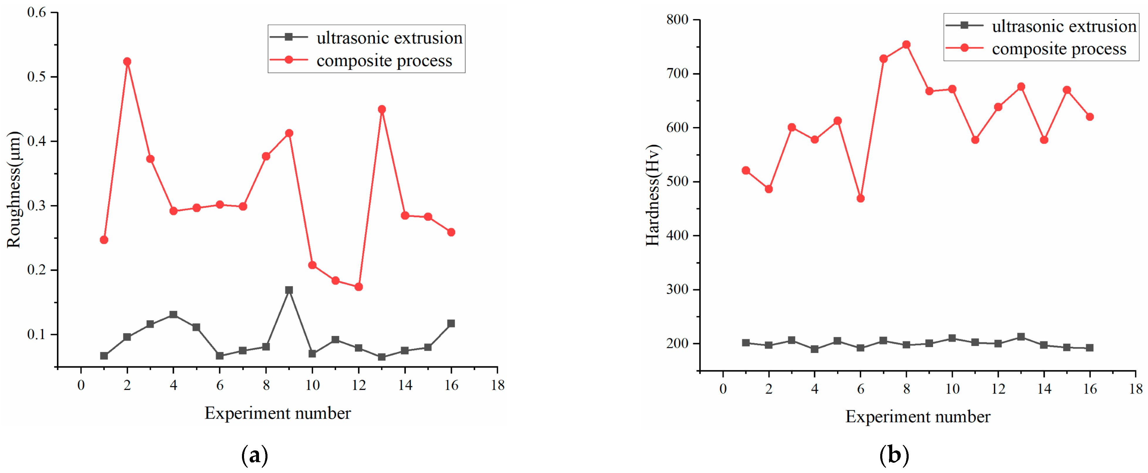
The surface roughness and hardness of the two processes are compared, as shown in Figure 8. The surface roughness values of the two processes remain at a low level, as shown in Figure 8a. The surface roughness of the composite process is higher than ultrasonic extrusion; there are two reasons for this. One is that the high hardness after low-temperature chromizing penetration decreases the effect of ultrasonic vibration extrusion and plastic deformation requires more energy. Another is that chromizing will increase the roughness of the unfinished surface. If the rotational speed, the feed and static extrusion amount remain unchanged, to achieve the same roughness of single ultrasonic extrusion, more ultrasonic energy injection is required to cause the machined surface to produce more plastic deformation.
At the same time, the surface hardness of the composite process is higher than the ultrasonic vibration extrusion process, as shown in Figure 8b, since both the low-temperature chromium penetration and the ultrasonic vibration extrusion significantly increase the surface hardness, and its surface hardness is increased by 2.55 times compared with the ultrasonic extrusion process.
Comparing the effects of process parameters on surface roughness and hardness after the two processes, the results of the range analysis are shown in Table 3 and Table 4.
In addition, note that the optimal solution for the ultrasonic extrusion process and the composite process needs to consider the simultaneous optimization of surface roughness and hardness. The smaller the surface roughness and the higher the hardness of the workpiece, the better the surface quality of the workpiece. The range method is used to determine the order of the influencing factors of surface roughness and hardness; then, the optimal solutions are obtained by comparing the values of surface roughness and hardness at each level of each factor, and finally the optimal solutions of ultrasonic extrusion process and composite process are obtained by taking both into account. The following are the details. Range analysis means that the change of the value of any factor within the test range will lead to a greater change in the value of the test index, i.e., the column with the largest range is the factor whose level has the greatest impact on the test result, i.e., the most important influencing factor. Usually, the range of each column is not equal, which indicates that the level change of each factor has different effects on the test results. R is the difference between the maximum value and the minimum value of average index value at each level on any list of factors, i.e., range R is calculated by R = max {K1, K2, K3, K4}–min {K1, K2, K3, K4} on any column. Max {K1, K2, K3, K4} and min {K1, K2, K3, K4} represent the maximum and minimum values of K1, K2, K3 and K4, respectively. For example, in the first column of Table 3, the maximum Ki is K1 = 0.41, and the minimum Ki is K2 = 0.334, so R = 0.41 − 0.334 = 0.076. Generally, the range R of each column is unequal, which means that the influence of the change in the level of each factor on the test results is different. The greater the range, the greater the change of the values of the factors in the test range will lead to greater changes in the values of the surface roughness and hardness.
Thus, the column with the largest range indicates that this factor has the greatest impact on the test results, which is the most important factor. Similarly, it can be calculated that the range of the second column is 0.104, and the range of the third column is 0.1. In the ultrasonic extrusion process, factor B (i.e., feed speed) is the factor that has the greatest impact on the test results, factor C (i.e., static extrusion amount) takes the second place, and factor A (i.e., spindle speed) has the least impact. The smaller the workpiece surface roughness, the higher the hardness, and the better the surface quality. For factor B, the roughness of Level 2 is the smallest. Similarly, for factor C, the roughness of Level 4 is the smallest. For factor A, the roughness of Level 2 is the smallest. Hence, the optimal solution of surface roughness is B2C4A2. Similarly, for the hardness, the descending order of influencing factors is BCA, i.e., the feed speed, spindle speed and static extrusion amount. The optimal solution is B1C4A3.
The optimal solution considering both the surface roughness and the hardness is analyzed. Factor B is the main factor for both hardness and roughness. If the hardness difference between B1 and B2 is not significant, then B1 is chosen. The surface roughness of A1 is lower than that of A1, and if the hardness difference between A1 and A2 is small, then A2 is chosen. C4 is chosen since it is the optimal surface roughness and hardness factor. Therefore, the optimal solution considering roughness and hardness is B1A2C4.
Table 4 shows the roughness of the composite process, and the descending order of the factor influence is ACB, which stands for spindle speed, static extrusion amount, and feed. A3B4C1 is the best solution for surface roughness. The descending sequence of factor influence for hardness is CBA, i.e., static extrusion quantity, feed, spindle speed, and its ideal solution is C4B4A2.
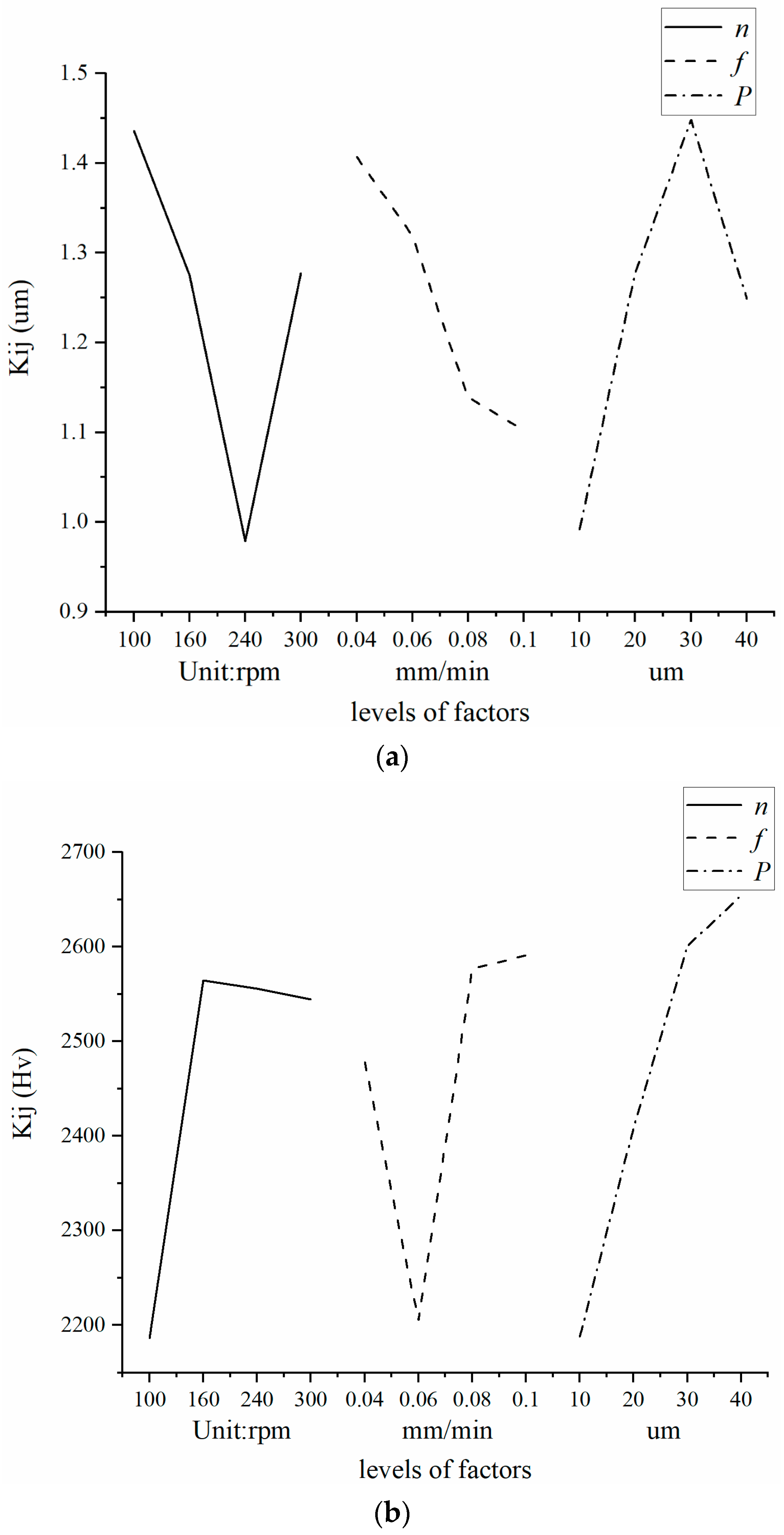
The optimal solution considering both the surface roughness and the hardness is analyzed. For factor A, it is the main factor of roughness and the last factor of hardness; then, A3 is selected. Factor B is the second factor of both roughness and hardness, and B4 is the optimal factor for both the surface roughness and the hardness; then, B4 is selected. Factor C is the main factor of the hardness and the last factor of the roughness; then, C4 is selected. Thus, the optimal solution considering both roughness and hardness is A3B4C4. The visual analysis of the two processes is shown in Figure 9 and Figure 10. The composite process can obtain higher hardness than the ultrasonic extrusion, and its surface roughness remains at a low level, although it is relatively large.
To study comprehensively the influences of the machining parameters, i.e., spindle speed, feed and static extrusion on the machined surface roughness and hardness, the second-order response surface method is used to establish the relationship between surface properties and machining parameters [31]. The equation of this method is given by
y = β 0 + i n β i x i + i n β i i x i 2 + i n β i j x i x j + ε ,
where, β 0 is a constant, n is the number of factors, β i is the linear coefficient, x i and x j are processing parameters, β i i and β i j is the coefficient of quadratic term, ε is the error of experimental data.
The model coefficients are determined by multivariate data analysis of the orthogonal test data in Table 2. The model of the ultrasonic extrusion and the composite process is given by
R u = 12 n 26326 f + 146 P + 232812 f 2 P 2 48 n f 378 f P 590 H u = 564 n + 2178486 f + 7988 P 3 n 2 7015625 f 2 + 57 P 2 + 12757 n f + 26 n P 171926 f P + 1907587 ,
R c u = 21 n + 88913 f + 330 P + 79687 f 2 3 P 2 234 n f 2662 f P 518 H c u = n 8942 f + 12 P + 44914 f 2 + 18 n f 3 f P + 512 ,
where subscripts u and c u represent the ultrasonic extrusion and the composite process, respectively. R and H represent the surface roughness and hardness, respectively.
Through these mathematical models, the roughness and hardness under composite process and ultrasonic process can be well predicted and analyzed, the influence of spindle speed, feed and static extrusion amount on workpiece surface roughness and surface hardness can be analyzed, and the process parameters can also be optimized by using this model.
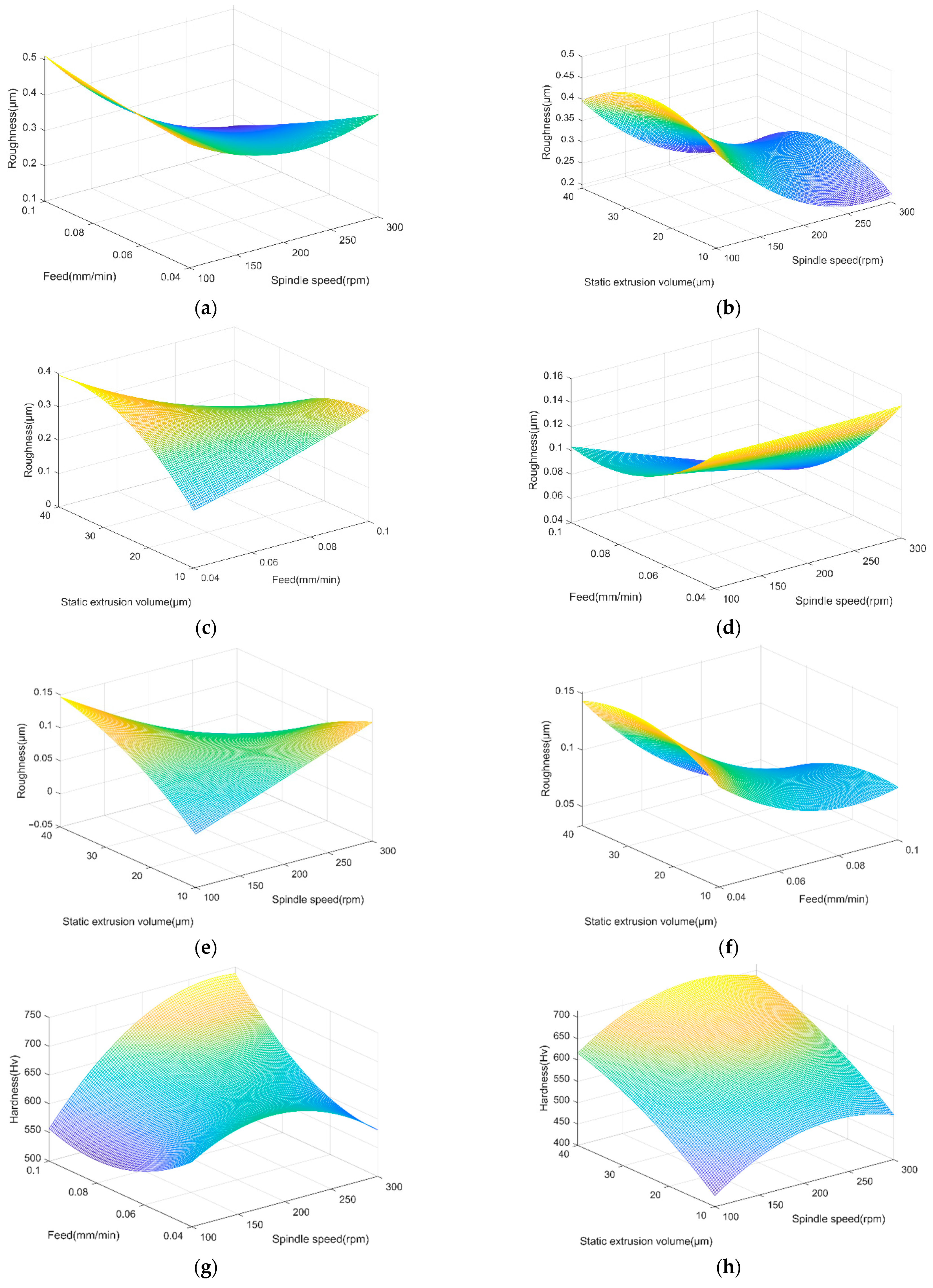
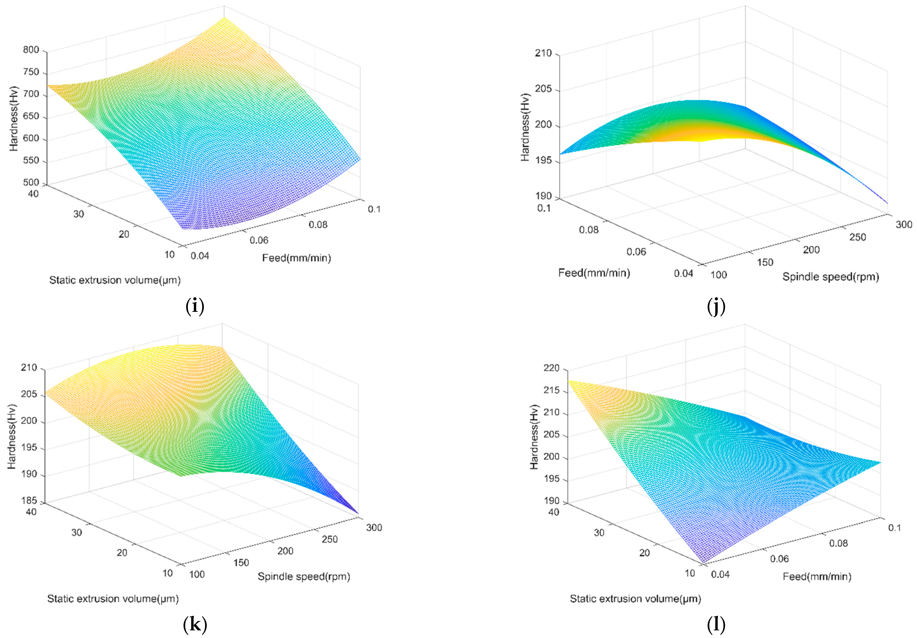
Based on the established response surface model, the response surfaces reflecting the relationship of the target value (i.e., the surface roughness and hardness) and the interaction of each two parameters are drawn, as shown in Figure 11. The interaction f × P of both two processes have a significant impact on the surface roughness and surface hardness, as shown in Figure 11c,f,i,l. The interaction n × f of both processes has a small influence, as shown in Figure 11b,e,h,k. The interaction n × f has no significant effect on surface roughness and surface hardness, as depicted in Figure 11a,d,g,j.
The relationships between process parameters are nonlinear. The results show that for the composite process, the spindle speed is negatively correlated with the surface roughness, and the feed and static extrusion amount are positively correlated with the surface roughness. By comparing the color changes, the interaction between the spindle speed and the feed has a greater impact on the surface roughness, as shown in Figure 11a,b,c. Feed, spindle speed and static extrusion amount are positively correlated with surface hardness. The interaction between spindle speed and static extrusion amount has a greater impact on surface roughness, as shown in Figure 11j,h,i. For the ultrasonic extrusion process, the feed is negatively related to the surface roughness, the spindle speed and the static extrusion amount are positively related to the surface roughness, and the interaction between the feed and the static extrusion amount has a greater impact on the surface roughness, as shown in Figure 11d,e,f. Spindle speed is negatively correlated with surface hardness, and feed and static extrusion amounts are positively correlated with surface hardness. The interaction between feed and static extrusion amount has a greater impact on surface hardness, as shown in Figure 11j,k,l. This is of guiding significance for the design of optimal parameter combination and the processing of workpieces in practice.

4.2. Comparison with Previous Research

In this section, the surface roughness reduction rate and hardness increase rate of the composite process compared with the stainless steel substrate are compared with those of the ultrasonic surface strengthening process in [32,33], as shown in Table 5. The effects of initial matrix, initial roughness and initial hardness can be ignored when adopting the roughness reduction rate and hardness increase rate.
Because of the high surface hardness of chromizing and the diminished impact of the plastic flow effect brought on by ultrasonic vibration, the roughness reduction ratio in this paper is lower than that in [32,33]. The ultrasonic vibration frequency used in this paper is much higher than that in [33], but the roughness reduction ratio is not significantly different from that in [33]. The intensity of the impact times will increase on the surface as the ultrasonic vibration frequency rises, which is to increase the roughness reduction ratio.
Compared to [32,33], the hardness increase rate in this paper is significantly higher. This is so that the low-temperature chromizing process used in this study can add active elements such as chromium to the matrix’s surface, preventing crack growth, lowering surface tension, and significantly raising surface hardness.
As a result, the composite process used in this paper can significantly increase the matrix’s hardness and satisfy the actual high hardness requirements while accounting for roughness.

4.3. Analysis of Machined Surface Topography

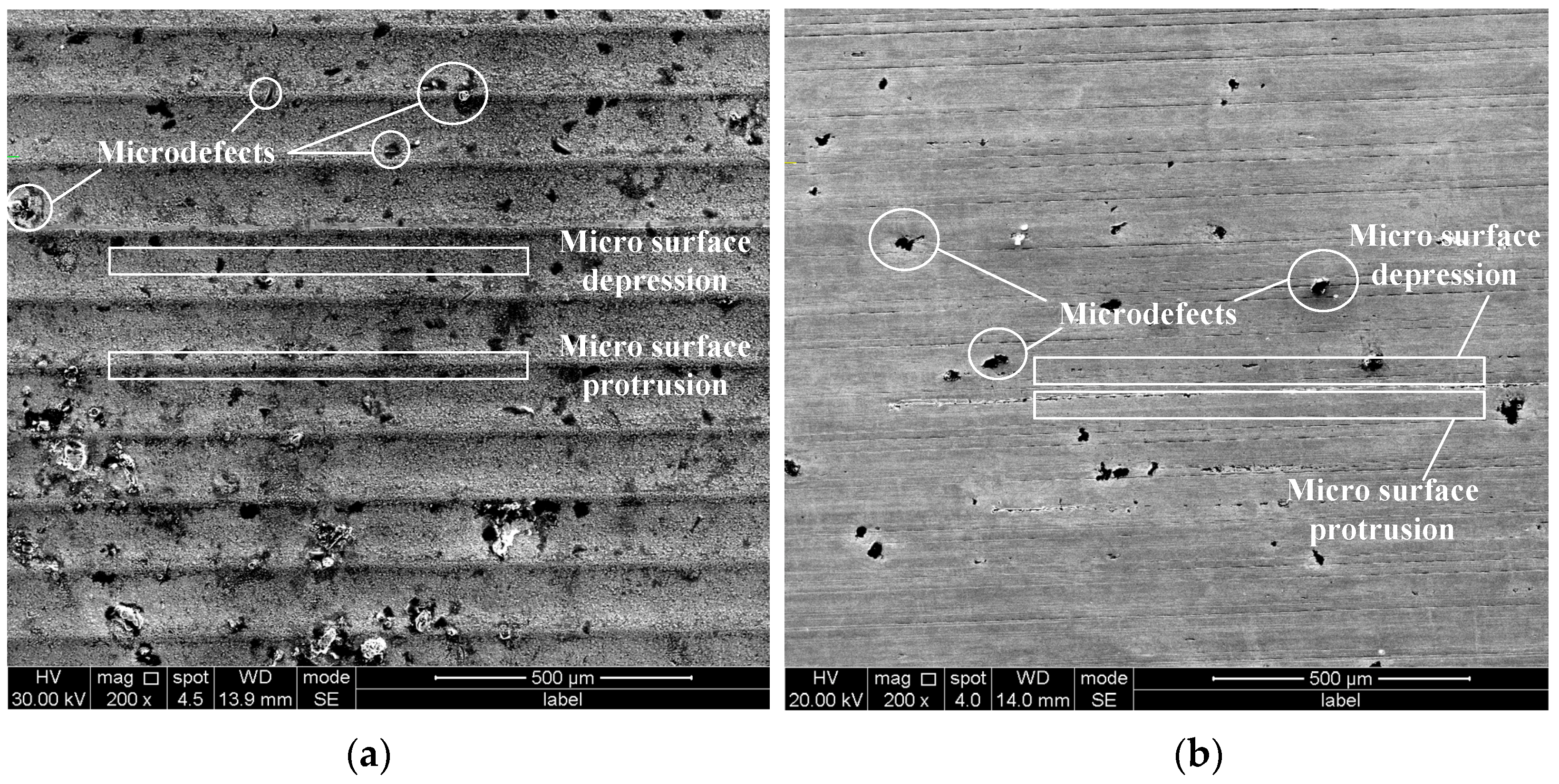
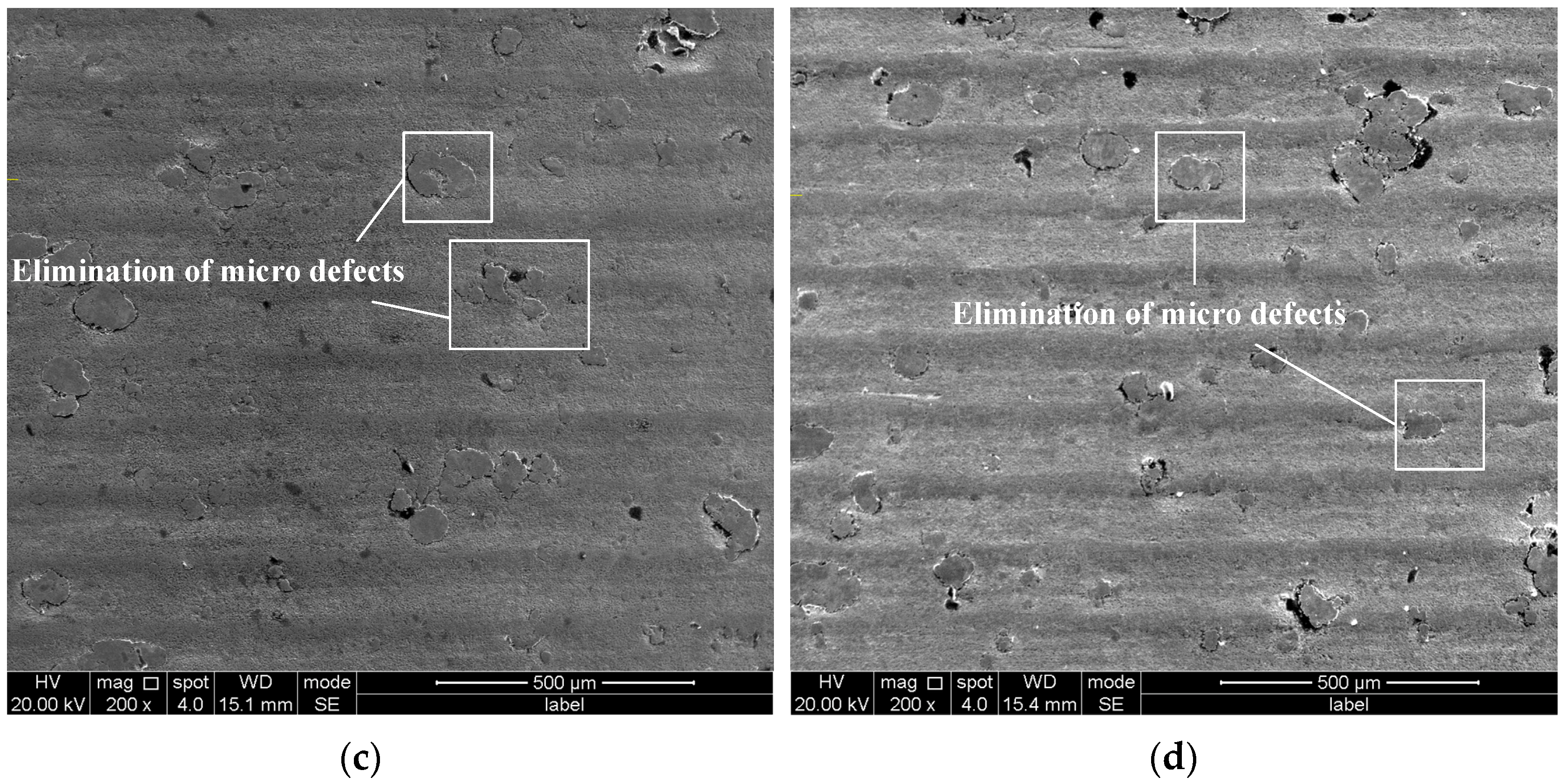
A comparison of the surface morphology is shown in Figure 12, where Figure 12a shows the result of the chromizing surface, Figure 12b–d shows the surfaces after the ultrasonic extrusion and the composite process. Here, the processing parameters of Figure 12b are n = 160   rpm , f = 0.06   mm / r and P = 10   μ m , the processing parameters of Figure 12c are n = 240   rpm , f = 0.08   mm / r and P = 10   μ m , and the processing parameters of Figure 12d are n = 240   rpm , f = 0.1   mm / r and P = 20   μ m .
The surface after the chromizing treatment is extremely uneven and rough with prominent gullies, as shown in Figure 12, and the surface of the stainless steel is smoother after the ultrasonic extrusion process. It can be seen from Figure 12a,b that there are micro surface protrusions and depressions on the rough surface, as well as many microdefects, including microscopic cavities, microscopic pull marks and microscopic double skin. Although the micro surface protrusions and depressions in Figure 12b are not obvious, the surface still regularly arranges the micro surface protrusions and depressions because the stainless steel matrix displays low strength and high plastic fluidity compared with the chromizing matrix.
The surface obtained by the composite process is shown in Figure 12c,d. Compared with the chromizing surface, its microscopic surface is much smoother, but there are still many bulges although the distribution of chromizing layer is not uniform, causing the uneven distribution of the skin thickness formed by the extrusion. As shown in Figure 12c,d, the microdefects on the surface machined by the composite process will also be reduced, because the plastic flow will eliminate the microdefects.
Compared with the results shown in Figure 12a,c,d, the micro surface protrusion on the chromizing surface is plastic-deformed by ultrasonic extrusion and flattened and filled into the micro surface depression, leading to the slight surface roughness after ultrasonic extrusion. The ultrasonic vibration energy not only promotes the plastic flow of the machined surface, but also reduces the defects of the machined surface, e.g., the cavity. Comparing the results depicted in Figure 12b–d, the effect of ultrasonic vibration on eliminating micro surface protrusion and filling micro surface depression of the chromizing surface is not as good as that of the stainless steel due to the high hardness of the chromizing surface, leading to high surface roughness. Compared with the results of Figure 12c,d, the increase of P and f leads to more plastic deformation, and the surface flatness decreases. In addition, some of the micro surface protrusion on the surface is extruded higher by the extrusion of the micro surface depression. With the decreasing f, the same length of the machined surface receives more ultrasonic impact, which makes the microscopic surface morphology smoother, and the microscopic defects are reduced accordingly.

5. Conclusions

The research proposes a surface modification process by combining low-temperature chromizing and ultrasonic extrusion on 304 stainless steel, which is validated by a set of experiments. The influence of processing parameters on surface qualities is researched as well. The conclusions are as follows:
(1)
The surface hardness of the chromizing and ultrasonic extrusion combined process and the ultrasonic vibration extrusion process are higher than the original surface hardness, and the surface hardness of the combined process is about 2.55 times higher than the ultrasonic vibration extrusion process.
(2)
Both the proposed method and ultrasonic extrusion reduce the surface roughness. However, the surface roughness of the proposed method is higher than that of the ultrasonic extrusion.
(3)
The optimized process parameters of the low temperature chromizing and ultrasonic extrusion composite process are spindle speed 240 rpm, feed 0.1 mm/r and static extrusion amount 40 μm. As a result, the processing stainless steel materials with high hardness and roughness is lower than Ra 0.8 μm.

Author Contributions

Y.C.: Conceptualization, Methodology, Data curation, Writing—original draft. L.Z.: Supervision, Methodology, Writing—review & editing. W.F.: Conceptualization, Methodology, Writing—review & editing, Supervision. All authors have read and agreed to the published version of the manuscript.

Funding

This research received no external funding.

Institutional Review Board Statement

Not applicable.

Informed Consent Statement

Not applicable.

Data Availability Statement

Not applicable.

Conflicts of Interest

The authors declare no conflict of interest.

References

  1. Park, J.H.; Kang, Y. Inclusions in stainless steels—A Review. Steel Res. Int. 2017, 88, 1700130. [Google Scholar] [CrossRef]
  2. Zhao, B.; Xu, G.X.; He, F. Present status and prospect of ultra-high strength steel applied to aircraft landing gear. J. Aeronaut. Mater. 2017, 37, 1–6. [Google Scholar]
  3. Dong, Z.; Li, Y.; Lee, B.; Babkin, A.; Chang, Y. Research status of welding technology of ferritic stainless steel. Int. J. Adv. Manuf. Technol. 2021, 118, 1–27. [Google Scholar] [CrossRef]
  4. Gardner, L. Stability, and design of stainless-steel structures—Review and outlook. Thin-Walled Struct. 2019, 141, 208–216. [Google Scholar] [CrossRef]
  5. Francis, R.; Byrne, G. Duplex stainless steels-alloys for the 21st century. Metals 2021, 11, 836. [Google Scholar] [CrossRef]
  6. Liu, L.; Fan, C.L.; Sun, H.Y. Research progress of alumina-forming austenitic stainless steels: A review. Materials 2022, 15, 3515. [Google Scholar] [CrossRef]
  7. Zhang, Q.; Xu, S.; Zhang, Z.Q. Residual stress and microhardness evolution induced by conventional and ultrasonic shot peening. Mater. Sci. Technol. 2022, 38, 436–443. [Google Scholar] [CrossRef]
  8. Meng, Y.; Deng, J.X.; Wu, J.X. Improved interfacial adhesion of AlTiN coating by micro-grooves using ultrasonic surface rolling processing. J. Mater. Process. Technol. 2022, 304, 117570. [Google Scholar] [CrossRef]
  9. Kumar, S.; Kumar, D.; Singh, I.; Rath, D. An insight into ultrasonic vibration assisted conventional manufacturing processes: A comprehensive review. Adv. Mech. Eng. 2022, 14, 16878132221107812. [Google Scholar] [CrossRef]
  10. Tian, H. Chromizing subsequent solid solution nitriding multiple process of 304 stainless steel. Heat Treat. Technol. Equip. 2006, 4, 29–32. [Google Scholar]
  11. Blaha, F.; Langenecker, B. Tensile deformation of zinc crystal under ultrasonic vibration. Sci. Nat. 1955, 42, 556. [Google Scholar]
  12. Rozner, A.G. Effect of ultrasonic vibration on coefficient of friction during strip drawing. J. Acoust. Soc. Am. 1971, 49, 1368–1371. [Google Scholar] [CrossRef]
  13. Hayashi, M.; Jin, M.; Thipprakmas, S. Simulation of ultrasonic-vibration drawing using the finite element method. J. Mater. Process. Technol. 2003, 140, 30–35. [Google Scholar] [CrossRef]
  14. Lucas, M.; Daud, Y. A finite element model of ultrasonic extrusion. J. Phys. Conf. Ser. 2009, 181, 012027. [Google Scholar] [CrossRef] [Green Version]
  15. Manousakas, I.; Lin, G.H.; Chang, S.J. Application of ultrasonic extrusion in the preparation of liposomes. In Proceedings of the 2010 4th International Conference on Bioinformatics and Biomedical Engineering, Chengdu, China, 18–20 June 2010; pp. 1–4. [Google Scholar]
  16. Bozdana, A.T.; Gindy, N.N.; Li, H. Deep cold rolling with ultrasonic vibrations—A new mechanical surface enhancement technique. Int. J. Mach. Tools Manuf. 2005, 45, 713–718. [Google Scholar] [CrossRef]
  17. Tsuji, N.; Tanaka, S.; Takasugi, T. Effect of combined plasma-carburizing and deep-rolling on notch fatigue property of Ti-6Al-4V alloy. Mater. Sci. Eng. A 2009, 499, 482–488. [Google Scholar] [CrossRef]
  18. Dong, Z.; Zhou, T.; Liu, J.; Zhang, X.; Shen, B.; Hu, W.; Liu, L. Effects of pack chromizing on the microstructure and anticorrosion properties of 316 L stainless steel. Surf. Coat. Technol. 2019, 366, 86–96. [Google Scholar] [CrossRef]
  19. Ruan, M.Y.; Peng, X.J.; Zhuang, F.J.; Zhu, X.Y. Study on fatigue behavior of plasma chromizing strengthening layer on biphasic titanium alloy. J. Mech. Strength 2021, 43, 442–446. [Google Scholar]
  20. Wang, Z.M.; Li, Q.D.; Wang, H.; Wang, H.L.; Hu, J.; Zhao, S.X. Effect of ultrasonic impact on the friction and wear properties of chromized layer of 65 Mn steel. Surf. Technol. 2021, 8, 1–11. [Google Scholar]
  21. Dong, Z.H. Research on the Anti-Corrosion Properties of Surface Chromizing Layer on 316 L Stainless Steel; Shanghai Jiao Tong University: Shanghai, China, 2020; pp. 45–48. [Google Scholar]
  22. Tang, X.G.; Dai, M.J.; Wei, C.B.; Kuang, T.C.; Lin, S.S.; Hou, H.J. Influence of solid chromizing doped with various rare earths on microstructures and properties of Cr-RE coatings fabricated by pack cementation. Surf. Technol. 2018, 47, 157–164. [Google Scholar]
  23. Zheng, J.X.; Liu, C.S.; Zhang, Y.M. Basic research on ultrasonic extrusion for 45 steel shaft. Key Eng. Mater. 2010, 455, 288–292. [Google Scholar] [CrossRef]
  24. Wang, H.Y. Research on the Ultrasonic Extrusion Strengthening Technology for Hollow Axle Material of High-Speed Train; Beijing Jiaotong University: Beijing, China, 2015; pp. 73–76. [Google Scholar]
  25. Zhou, H.; Zhang, J.; Yu, D.; Feng, P.; Wu, Z.; Cai, W. Advances in rotary ultrasonic machining system for hard and brittle materials. Adv. Mech. Eng. 2020, 11, 1687814019895929. [Google Scholar] [CrossRef] [Green Version]
  26. Zhu, Y.L.; Wang, Y.L.; Bian, F.L.; Hou, S.; Xie, J. Progresses on research and application of metal ultrasonic surface enhancement technologies. J. Mech. Eng. 2014, 50, 35–45. [Google Scholar] [CrossRef]
  27. Lou, Y.; Liu, X.; He, J.; Long, M. Ultrasonic-assisted extrusion of ZK60 Mg alloy micropins at room temperature. Ultrasonics 2018, 83, 194–202. [Google Scholar] [CrossRef] [PubMed]
  28. Zhang, C.H. Parameter Determination of Constitutive Model of 18CrNiMo7-6 and Theoretical Analysis and Simulation of Ultrasonic Rolling; Zhengzhou University: Zhengzhou, China, 2021; pp. 37–38. [Google Scholar]
  29. Zhou, Z.; Yao, C.; Zhao, Y.; Wang, Y.; Tan, L. Effect of ultrasonic impact treatment on the surface integrity of nickel alloy 718. Adv. Manuf. 2021, 9, 160–171. [Google Scholar] [CrossRef]
  30. Liu, Y. Research on the Theory of Ultrasonic Surface Rolling Processing and Mechanical Properties of Metal Surface; Tianjin University: Tianjin, China, 2012; pp. 33–37. [Google Scholar]
  31. Song, H.W.; Dan, J.Q.; Li, J.L. Experimental study on the cutting force during laser-assisted machining of fused silica based on the Taguchi method and response surface methodology. J. Manuf. Process. 2019, 38, 9–20. [Google Scholar] [CrossRef]
  32. Zhang, Q.; Cao, J.; Wang, H. Ultrasonic surface strengthening of train axle material 30CrMoA. Procedia Cirp 2016, 42, 853–857. [Google Scholar]
  33. Fang, S.; Zhang, Q.; Zhao, H.; Yu, J.; Chu, Y. The design of rare-earth giant magnetostrictive ultrasonic transducer and experimental study on its application of ultrasonic surface strengthening. Micromachines 2018, 9, 98. [Google Scholar] [CrossRef]
Figure 1. Principle diagram of Solid Power Chromizing process.
Applsci 12 11729 g001
Figure 2. Chromizing temperature curve.
Applsci 12 11729 g002
Figure 3. Cross-section morphology of chromizing layer of 304 stainless steel.
Applsci 12 11729 g003
Figure 4. Ultrasonic vibration extrusion system.
Applsci 12 11729 g004
Figure 5. Experimental setup. (a) Numerical control machine; (b) workpiece and extrusion tool; (c) Control and support devices; (d) execution device.
Applsci 12 11729 g005
Figure 6. Motion trajectory of the tooltip relative to the workpiece.
Applsci 12 11729 g006
Figure 7. Test samples after the surface treatment process. (a) Test sample after the ultrasonic vibration extrusion. (b) Test sample after the composite process.
Applsci 12 11729 g007
Figure 8. Comparison of two processes on surface roughness and hardness. (a) Surface roughness. (b) Surface hardness.
Applsci 12 11729 g008
Figure 9. Visual analysis of the ultrasonic extrusion. (a) Surface roughness. (b) Surface hardness.
Applsci 12 11729 g009
Figure 10. Visual analysis of the composite process. (a) Surface roughness. (b) Surface hardness.
Applsci 12 11729 g010
Figure 11. Multiple factor interactive response surfaces. (a) R c u n × f . (b) R c u n × P . (c) R c u f × P . (d) R u n × f . (e) R u n × P . (f) R u f × P . (g) H c u n × f . (h) H c u n × P . (i) H c u f × P . (j) H u n × f . (k) H u n × P . (l) H u f × P .
Applsci 12 11729 g011aApplsci 12 11729 g011b
Figure 12. Comparison of the surface morphology. (a) Chromizing surface. (b) Ultrasonic extrusion. (c) Composite process. (d) Composite process. Parameters: (b) n = 160   rpm , f = 0.06   mm / r and P = 10   μ m ; (c) n = 240   rpm , f = 0.08   mm / r and P = 10   μ m ; (d) n = 240   rpm , f = 0.1   mm / r and P = 20   μ m .
Applsci 12 11729 g012aApplsci 12 11729 g012b
Table 1. Three-factor and four-level orthogonal test table.
Factor Spindle   Speed   n
(rpm)
Feed   f (mm/r) Static   Extrusion
  Amount   P (μm)
Level
11000.0410
21600.0620
32400.0830
43000.140
Table 2. Test results.
No.Spindle Speed n
(rpm)
Feed f (mm/r)Static Extrusion Amount P (μm)Roughness Ra (μm)Hardness (Hv)
Composite ProcessUltrasonic Extrusion Composite ProcessUltrasonic Extrusion
11000.04100.2470.067520.92201.58
21000.06200.5240.096486.59197.03
31000.08300.3730.116601.00206.28
41000.1400.2920.131578.12189.77
51600.04200.2970.111612.99204.82
61600.06100.3020.067469.35191.86
71600.08400.2990.075728.08205.54
81600.1300.3770.081754.16197.68
92400.04300.4130.169667.98200.43
102400.06400.2080.07671.80209.97
112400.08100.1840.092577.55202.36
122400.1200.1740.079638.75200.00
133000.04400.450.065676.37212.49
143000.06300.2850.075577.58197.30
153000.08200.2830.08670.12192.96
163000.1100.2590.117620.23192.04
Table 3. Range analysis of the ultrasonic extrusion.
TreatmentFactorsSpindle Speed AFeed BStatic Extrusion Amount C
Surface roughness Ra10.410.4120.343
20.3340.3080.366
30.410.3630.441
40.3370.4080.341
Range R0.0760.1040.1
Surface hardness1794.66819.32787.84
2799.90796.16794.81
3812.75807.14801.68
4794.79779.49817.78
Range R18.0939.8329.93
Table 4. Range analysis of the composite process.
Evaluation IndexFactorsSpindle Speed AFeed BStatic Extrusion Amount C
Surface roughness Ra11.4361.4070.992
21.2751.3191.278
30.9791.1391.448
41.2771.1021.249
Range R0.4570.3050.456
Surface hardness12186.642478.262188.04
22564.592205.322408.45
32556.072576.752600.73
42544.302591.262654.37
Range R377.95385.94466.33
Table 5. Comparison with references.
Research ItemSurface Roughness Reduction Rate (%)Hardness Increase Rate (%)Ultrasonic Frequency (kHz)
[32]95.659.530
[33]65.2310.2615
This research60.8627541.243
Publisher’s Note: MDPI stays neutral with regard to jurisdictional claims in published maps and institutional affiliations.