Article

Local-Moment-Driven Robust Reversible Data Hiding

1
Department of Computer Science & Engineering, Galgotias College of Engineering & Technology, Greater Noida 201310, Uttar Pradesh, India
2
Department of Computer Science & Engineering, ABES Engineering College, Ghaziabad 201009, Uttar Pradesh, India
3
Department of Information Technology, Babu Banarasi Das Engineering College, Lucknow 226028, Uttar Pradesh, India
4
Department of Software Convergence, Andong National University, Andong 36729, Gyeongbuk, Republic of Korea
*
Author to whom correspondence should be addressed.
Appl. Sci. 2022, 12(22), 11826; https://doi.org/10.3390/app122211826
Submission received: 5 September 2022 / Revised: 13 October 2022 / Accepted: 15 November 2022 / Published: 21 November 2022
(This article belongs to the Special Issue Development of IoE Applications for Multimedia Security)

Abstract

:
In this paper, a local-moment-driven robust reversible data hiding (LM-RRDH) scheme is proposed, which can provide security to hidden messages against unintentional modifications. The proposed LM-RRDH decomposes an image into LSB and MSB planes and then embeds the secret information into the MSB image so that intrusion by unintentional modifications can be avoided. In addition, the proposed scheme utilizes the prevalent correlation among the pixels on the MSB plane for optimal embedding. In the proposed scheme, a cover image is partitioned into sub-blocks at first, and pixel groups in the sub-block are formed according to local moment and moment-of-moment so that similar-intensity pixels can be grouped into the same group. Next, the secret data is embedded into the pixels of each group by selecting a pairwise embedding strategy adaptively which is based on the number of pixels in each group. As a result, the proposed LM-RRDH can limit the distortion while providing a decent embedding capacity. Further, a protection against non-malicious attacks such as Joint Photographic Experts Group (JPEG) compression is also provided. The experimental results show that the proposed scheme provides a superior quality to the previous works while providing a comparable embedding capacity.

1. Introduction

Due to the massive improvement of hardware technology and the emergence of network-based cracking technology, traditional information security has been challenged [1]. Therefore, continuous improvement in security methods has become a present need. One of the improved methods is a reversible data hiding (RDH) method which allows the embedding of confidential information into a multimedia carrier such as an image, video, or audio and enables lossless retrieval of the secret information from the carrier along with complete restoration of the host carrier [2]. As a result, it makes the detection of secret information in the intercepted multimedia carrier difficult for illegal hackers. In turn, stealing the hidden confidential information becomes a difficult task [3]. Because of the aforementioned advantage of RDH method, it has attracted a lot of attention from researchers working in the field of security. Therefore, multiple spatial-domain-based RDH methods have been introduced in the literature, which can be categorized into the following categories: namely (a) lossless compression [4,5,6], (b) difference expansion [7,8], and (c) prediction error expansion [9,10,11,12,13,14,15,16,17,18,19].
Among the aforementioned methods, prediction-error-expansion (PEE)-based RDH methods achieved more popularity due to their embedding efficiency. The first PEE-RDH method was introduced by Thodi and Rodriguez [9] in 2007. The PEE-RDH predicts the pixel values based on the correlation of neighbouring pixels and makes use of the difference error between the predicted and actual pixel value to embed the secret information. The correlation among the neighbouring pixels helps in generating sharper prediction error histograms (PEHs). It is noted that sharper PEHs generally result in better embedding efficiency. The next noteworthy work in the domain of PEE is Sachnev et al.’s method [10] that makes use of a rhombus predictor. It was argued in the work that a rhombus predictor can present the centre pixel most effectively. Therefore, the method improves the embedding efficiency significantly. Afterwards, a plethora of PEE-based research works based on different predictors, such as gradient-adjusted predictors (GAP) [11], deep-learning and machine-learning-based predictors [12], and sorting-based predictors [13] have been introduced. Among all of these, sorting (pixel value ordering)-based predictors provide high-fidelity images. In RDH methods based on pixel value ordering, the host image is partitioned into blocks and pixels of each block are sorted in ascending order. Next, the secret information bits are usually embedded into the extreme left and extreme right pixels of the sorted block by predicting their pixel values using the penultimate extreme left and right pixels, respectively, and modifying the errors by expanding/shifting the extreme left and right pixels to their extreme sides only [13,14]. Therefore, a sharper PEH is achieved, but the partial utilization of every pixel of each block negatively affects the embedding capacity. In addition to using different predictors for performance improvement, a noteworthy work based on a pairwise PEE was introduced by Ou et al. [15]. The pairwise PEE scheme claims and validates that adjacent prediction errors have correlation on similar lines as that of nearby pixels. Here, the pair of pixels were used simultaneously to embed the secret data using two-dimensional prediction error histogram modification by exploiting the correlation. The work of Ou et al. [15] was extended to improve the performance in [17,18]. A systematic survey of all the pixel-value-ordering-based reversible data hiding methods is presented in [19]. In addition to modifying the pixel values directly, another dimension added in the field of reversible-data-hiding works is embedding in encrypted images. Such works are popularly known as reversible data hiding in encrypted images (RDHEI) [20,21]. Many such works have been discussed in recent years which have been comprehensively reviewed in [22].
However, it has been observed that the robustness of the embedded secret information against the compression or other small alteration has still been a large concern in spatial-domain-based RDH schemes. Therefore, in this paper, a new local-moment-driven RRDH scheme is proposed to enhance the image quality while maintaining the embedding capacity. The contribution of the proposed LM-RRDH scheme can be briefly explained as follows:
(1)
The proposed LM-RRDH transforms the host image into two planes: MSB and LSB, and makes use of the image of the MSB plane for embedding the secret information so that the required robustness of the hidden data can be provided.
(2)
The image of the MSB plane is divided into sub-blocks, and pixel groups are formed to collect similar-intensity pixels in the same group. Therefore, highly correlated groups are formed to embed secret information.
(3)
Further, the dynamic selection of a pairwise embedding strategy based on the number of pixels in the group can help in achieving better quality while maintaining the embedding capacity.
(4)
As a result, the proposed LM-RRDH can provide superior quality while providing comparable embedding capacity.
The rest of the paper is organized as follows. Section 2 presents a literature review. The proposed local moment driven robust reversible data hiding scheme is introduced in Section 3. Section 4 presents the experimental results and analysis. Finally, it is concluded in Section 5.

2. Literature Review

This section is divided into two sub-sections. In the first sub-section, some of the existing robust reversible data hiding methods are briefly reviewed and followed by a detailed review of one of the closest existing scheme.

2.1. Review of Existing Robust Reversible Data Hiding Schemes

In 2003, Vleeschouwer et al. [23] introduced a semi-fragile lossless data-hiding technique which provides a certain level of protection against minor altercations. However, the technique has a fatal problem of salt-and-pepper noise which was addressed by Ni et al. [24,25]. In Ni et al.’s technique, the arithmetic average difference of a block is computed first and the secret message bits are embedded by shifting the difference. More specifically, the difference is shifted in the event that the bit is ‘1’; otherwise it remains unchanged. Thus, a higher degree of robustness along with a good quality stego-image is provided. In 2010, Zeng et al. [26] extended the work of [24,25] for doubling the embedding capacity by utilizing the different scenarios of the arithmetic difference. Deng et al. [27] discussed a robust image watermarking scheme based on histogram modification. The scheme computes the histogram of the cover image and embeds the information/watermark in the selected peak bins. The work [27] claimed that the scheme can resist against geometric distortions as well as common image processing operations. However, the scheme has limited embedding capacity. Afterwards, multiple robust reversible data hiding (RRDH) schemes, such as [28,29,30,31,32,33,34], were introduced to increase the embedding capacity while maintaining the robustness and providing a decent-quality stego-image. Among all the aforementioned RRDH schemes, a noteworthy introduction was written by Wang et al. [29], discussing a novel spatial-domain-based RRDH scheme in 2017. Wang et al.’s scheme makes use of significant bits for embedding the secret data by using the difference expansion method. Since the correlation among the most significant bits is significantly higher than the least significant bits, the proposed scheme can increase the embedding capacity. Additionally, the usage of a higher significant bit plane (HSB) of an image for embedding secret information increases the robustness when unintentional minor attacks such as JPEG compression make modifications in the lower bit plane. Therefore, the contents of the higher significant bit plane are intact. The work of [29] was extended by Kumar and Jung [30] to enhance the embedding capacity, along with image quality, while providing the same degree of robustness. Kumar and Jung used a two-layer embedding (TLE) strategy to embed the secret data into the HSB plane as in [29]. The scheme embeds the secret data into two layers by using a PEE strategy with the help of two sets of novel predictors. In addition, the proposed scheme carries out the expansion and shifting of histogram bins on the short tail side so that the distortion can be limited. Thus, the scheme increases the embedding capacity significantly, along with higher PSNR, while providing the same level of robustness as [29]. The brief review of the working process of the TLE scheme [30] is presented in the next section.

2.2. Detailed Review of Kumar and Jung’s TLE Scheme [30]

In 2020, Kumar and Jung [30] discussed the RRDH scheme using two-layer embedding (TLE) strategy. The TLE scheme provides good resistance against the minor altercations while providing high embedding capacity with decent quality stego-image. First, Kumar and Jung’s scheme decomposes the cover image into two planes, namely the most-significant-bit (MSB) and least-significant-bit (LSB) planes, by separating the user-defined number ( n ) of LSBs from all of the bits in each pixel of the image. It is obvious that each pixel ( P i , j ) of the image is represented by eight bits as its value ranges from 0 to 255. The pixel ( P i , j ) is decomposed into the MSB and LSB planes using the following equations:
P i , j = k = 0 n 1 b k 2 k + k = n 7 b k 2 k
where
P i , j L S B = k = 0 n 1 b k 2 k
P i , j M S B = k = n 7 b k 2 k
Here, P i , j L S B and P i , j M S B represent the LSB and MSB planes, respectively, for P i , j and b k   ϵ   { 0 ,   1 } represents the kth bit value of 8-bit binary representation of P i , j . By processing each pixel of the cover image ( I ), two images I L S B and I M S B are obtained.
To provide resistance against minor modifications, the TLE scheme embeds the secret information in the MSB plane. The image I M S B is represented in a checkboard pattern so that two independent sets of pixels— x -set in saffron and y -set in white—can be obtained as shown in Figure 1. Next, the x -set pixels are scanned and sorted according to their local complexity. The pixels are arranged into the ascending order of their complexity so that the pixels with the least complexity can be preferred for embedding the information. The preference helps in limiting the distortion, as the pixels with a lower local complexity are probably the most expanded, whereas higher-local-complexity pixels are probably the most shifted, thus causing undesired distortion.
Next, the TLE scheme embeds the secret information in each pixel of the image into two layers by using the PEE strategy. In the first layer, the pixel ( P i , j H S B ) is predicted and an error ( e 1   i , j H S B ) is calculated as follows:
e 1   i , j H S B =   P i , j H S B p ^ 1   i , j H S B
where p ^ 1   i , j H S B is the predicted pixel value determined using a selected predictor from the first set of given set of predictors. Next, the secret data bit S 1 D ϵ   { 0 ,   1 } is embedded using Equation (5) as follows:
P i , j M S B = { P i , j M S B + S 1 D   if   e 1   i , j H S B = 1 , P i , j M S B + 1   if   e 1   i , j H S B > 1 , P i , j M S B   if   e 1   i , j H S B < 1 .
Here, P i , j M S B is the marked pixel obtained after the first layer of embedding. To again embed the secret information bits in the pixel, another error ( e 2   i , j H S B ) is calculated using Equation (6) after the predicted pixel value determined using a selected predictor from the second set of given set of predictors.
e 2   i , j H S B =   P i , j H S B p ^ 2   i , j H S B  
Next, the secret data bit S 2 D ϵ   { 0 ,   1 } is embedded using Equation (7). It is to be noted whether the second-layer-predicted pixel value p ^ 2   i , j H S B is equivalent to the first-layer one. In other words, p ^ 1   i , j H S B then p ^ 1   i , j H S B are increased by one so that secret bits can be embedded into the pixels optimally.
P i , j M S B = { P i , j M S B S 2 D   if   e 2   i , j H S B = 1 , P i , j M S B 1   if   e 2   i , j H S B < 1 , P i , j M S B   if   e 2   i , j H S B > 1 .
Thus, a marked pixel value, P i , j M S B , is obtained. The same embedding process is repeated for each x-set pixel, followed by the y-set pixels to obtain the marked I M S B . The I L S B and I M S B are then concatenated to obtain the marked image I , which provides a high degree of resistance to hidden information against minor altercations. In addition, the TLE scheme provides a high embedding capacity with good quality marked image. In the proposed work, a new scheme which is an extension of with Kumar and Jung’s scheme [30] is proposed to increase the embedding efficiency while providing the same level of robustness. The detailed explanation regarding the proposed scheme is presented in the next section.

3. The Proposed Local-Moment-Driven Robust Reversible Data-Hiding Scheme

As discussed above, Wang et al. [29] and Kumar and Jung’s [30] schemes provide a good data hiding capacity with good resistance against unintentional minor modifications. However, the schemes do not efficiently exploit the prevalent correlation among nearby pixels of MSB plane-based images. To this end, a new local-moment-driven robust reversible data hiding (LM-RRDH) scheme, inspired by [35], based on pairwise prediction error expansion, is proposed. The LM-RRDH scheme embeds the secret information into MSBs of the cover image ( I ) of h × w pixels so that a certain level of resistance against unintentional alterations can be achieved as with [29,30]. First, the scheme segregates the certain number of LSBs from MSBs of each pixels to obtain two images, I M S B and I L S B , using Equations (2) and (3). The I M S B is then used for embedding the secret information so that correlation among the pixels of the image can be utilized at maximum. The proposed scheme is divided into two parts as follows.

3.1. Embedding Method

In this subsection, checkboard-scanning-based pixel grouping using local moment is discussed. Second, a new data-hiding method based on adaptive selection of embedding strategy is presented on auxiliary information for blind decoding. Finally, the embedding algorithm and its illustrative example is provided.

3.1.1. Checkboard Scanning Based Pixel Grouping Using Local Moment

For embedding the secret data, the image ( I M S B ) is partitioned into equal-sized non-overlapping blocks, preferably of 3 × 3 pixels, starting from pixel position ( 2 ,   2 ) to ( h 1 , w 1 ) . Then, x -set pixels (orange color shown in Figure 1 such as S x = { x 1 , x 2 , x 3 , x 4 , x 5 } ) of the first block are segregated into two groups that are based on the local moment of each pixel, and moment-of-moment of the block, using the following Equations (8)–(10), respectively.
μ i , j = [ 1 4 ( y i , j 1 + y i 1 , j + y i , j + 1 + y i + 1 , j ) ]
Here, y i , j 1 ,   y i 1 , j ,   y i , j + 1 ,   and y i + 1 , j are the surrounding pixels for the reference pixel, e.g., x i , j , for which the local moment ( μ i , j ) is calculated. For example, the local moment ( μ 3 ) for pixel x 3 can be calculated as follows when the pixels are numbered as in Figure 1:
μ 3 = [ 1 4 ( y 1 + y 2 + y 3 + y 4 ) ]
y 1 , y 2 , y 3 , and y 4 are the surrounding pixels for the reference pixel ( x 3 ) as per Figure 1. Next, the moment-of-moment of the block ( B k ) can be calculated using Equation (10) as follows:
k = [ 1 N m = 1 M μ m ]
where N denotes the count of pixels in the x-set of the block ( B k ) and m denotes the x -set pixel number of B k when the pixels are scanned in raster-scan manner. Next, the x -set pixels of B k are tagged and grouped into two groups, F G and S G , by using Equation (11).
x m = { F G ,   if   μ m < k S G ,   else
Therefore, every pixel ( x m ) from S x of B k is grouped either into the first group ( F G ), when the local moment ( μ m ) is less than the moment of moment ( k ) for the S x , or into the second group ( S G ) as per Equation (11). Next, the embedding of secret information in each of the groups ( F G , S G ) is carried out using the embedding strategy introduced in Section 3.1.2. The process of grouping and embedding is repeated for the y -set pixels (white color shown in Figure 1 such as S y = { y 1 , y 2 , y 3 , y 4 } ) with the updated block. Embedding in each and every block of the image, the marked-MSB plane ( I M S B ) is obtained, which is concatenated with I L S B to obtain the final stego-image ( I ).

3.1.2. Hiding Method Based on Adaptive Selection of Embedding Strategy

It has been observed from the analysis of the literature that pixel-value-ordering-based methods provide high-fidelity images, while the prediction-error-expansion (PEE)-based pixel-wise or pairwise embedding methods provide a high embedding capacity with decent quality stego-images. Therefore, the proposed RRDH method selects an adaptively embedding strategy among the enhanced pairwise improved pixel value ordering (EP-IPVO), enhanced pairwise prediction error expansion (EP-PEE) scheme and Sachnev’s prediction error expansion (S-PEE) based on the cardinality   ( # ) of the group (number of pixels in the group), so that the advantages of each of the methods can be exploited and optimal embedding is performed. More specifically, EP-IPVO is used to embed for cardinality ( # ) > 2 . In the case of cardinality ( # ) being equal to 2, EP-PEE is used for embedding the secret message. The embedding is carried out using S-PEE when cardinality ( # ) is equal to 1.
For applying the EP-IPVO, the pixels (e.g., x 1 ,   x N ) of the group are arranged in ascending order ( x π ( 1 ) , , x π ( N ) ) , where x π ( 1 ) x π ( N ) , π ( i ) < π ( j ) for x π ( i ) = x π ( j ) and i < j . Next, two prediction errors are calculated using Equations (12) and (13), respectively.
e 1   I P V O = x s - x t
e 2   I P V O = x u - x v
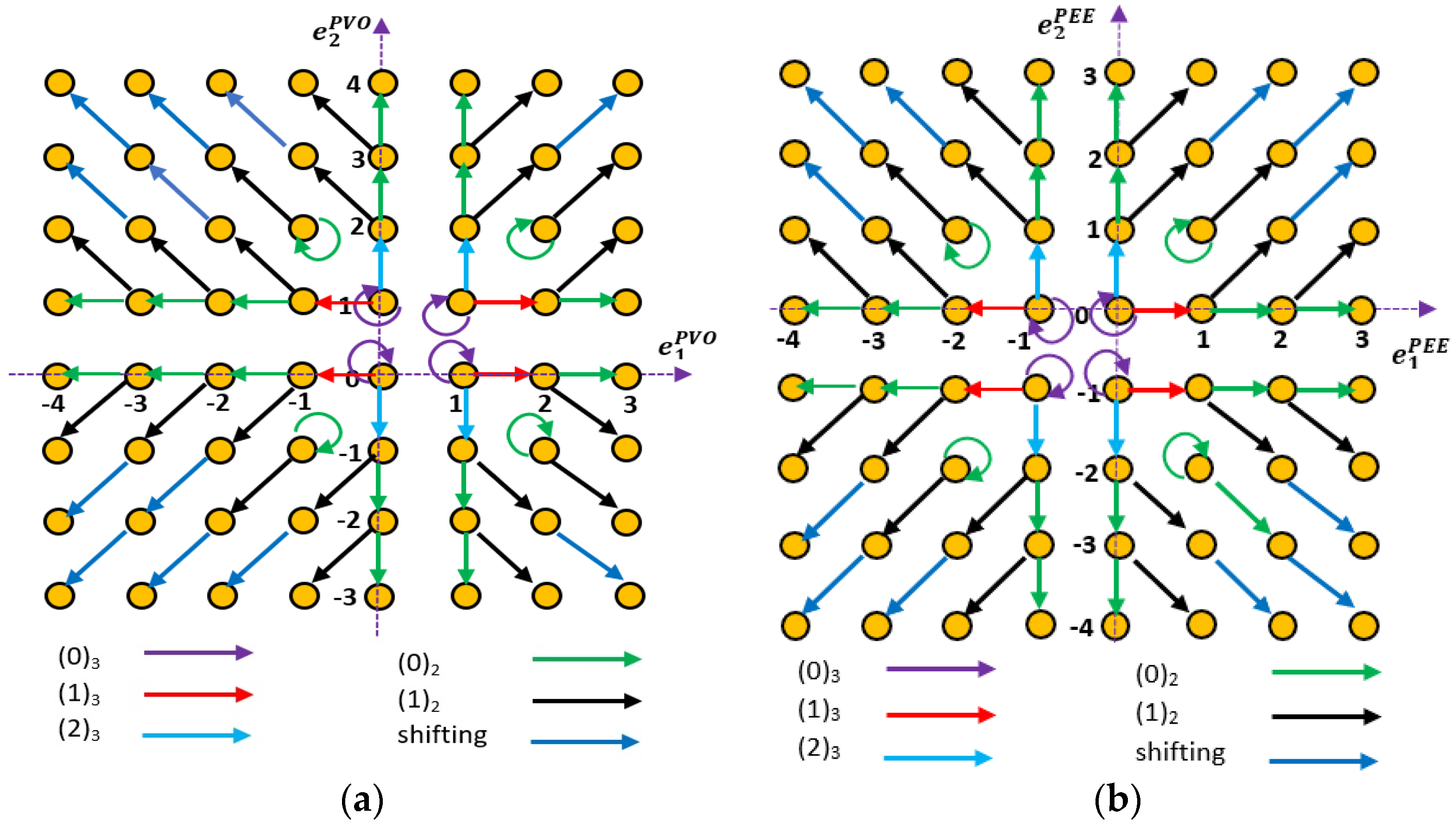
where s = m i n ( π ( 1 ) ,   π ( 2 ) ) , t = m a x ( π ( 1 ) ,   π ( 2 ) ) , u = m i n ( π ( N 1 ) ,   π ( N ) ) and v = m a x ( π ( N 1 ) ,   π ( N ) ) [11,12]. Next, the minimum pixel ( x π ( 1 ) ) and maximum pixel ( x π ( N ) ) are modified by a maximum of −1 and +1 to embed the secret data in the group. More specifically, the modification of the pixel values are carried out based on the pair of error values ( e 1   I P V O and e 2   I P V O ) and embedding bits using Figure 2a. Figure 2a essentially represents the prediction error modification based on the embedding bits, which modifies the minimum and/or maximum pixels of the group as per Equations (14) and (15), respectively.
x π ( 1 ) = x π ( 2 ) | e 1   I P V O |
x π ( N ) = x π ( N 1 ) + | e 2   I P V O |
Here, symbol | . | truncates the sign and gives the positive values and e 1   I P V O and e 2   I P V O represent the expanded errors obtained from Figure 2a. From Figure 2a, it can be observed that the EP-IPVO strategy tries to contain the distortion by limiting the modifications.
For applying the EP-PEE strategy on the pixels (e.g., x 1 ,   x 2 ) of the group, two prediction errors are calculated using Equations (16) and (17), respectively.
e 1   P E E = x 1 [ μ 1 ]
e 2   P E E = x 2 [ μ 2 ]
where [ μ 1 ] and [ μ 1 ] are the rounded-off local moments of the pixels x 1 and x 2 , respectively. Next, the modification of the prediction errors is performed using the EP-PEE mapping strategy [13] as shown in Figure 2b. The pixels ( x 1 ,   x 2 ) of the group are then modified using following Equations (18) and (19), respectively.
x 1 = [ μ 1 ] + e 1   P E E
x 2 = [ μ 2 ] + e 2   P E E
e 1   P E E and e 2   P E E represent the expanded errors obtained from Figure 2b. For applying the S-PEE strategy on the pixels (e.g., x 1 ) of the group, first a prediction error ( e S P E E ) is calculated, such as e S P E E = x 1 [ μ 1 ] . Next, the pixel is modified to embed the secret data bits using the following Equation (20).
x 1 = { x 1 + b 1   if   e S P E E = 0 , x 1 + 1   if   e S P E E > 0 , x 1 b 1   if   e S P E E = 1 , x 1 1   if   e S P E E < 1 ,
where b 1 is a bit of secret data that can be either ‘0’ or ‘1’. It can be observed from Equation (20) that a bit of secret information is embedded into the pixel if the prediction error ( e S P E E ) is either ‘0’ or ‘−1’, otherwise the pixel is shifted by one. Thus, overall, the maximum change made to a pixel is limited to ±1 as far as I M S B is concerned in isolation. However, the maximum change made to the cover image pixel is ± ( k = 0 n 1 2 k )   + 1, e.g., if n = 3 then it would be 8.

3.1.3. Auxiliary Information for Blind Decoding

To recover the original image and extract the secret information in a lossless manner, some auxiliary information needs to be embedded in the image along with the secret data. This information consists of the following components:
  • Details of location map: Though the proposed LM-RRDH scheme embeds the secret data in the MSB plane of the image, the problem of overflow (pixel value > k = n 7 2 k where n = 0 ,   1 ,   2 ,   3 , ,   7 or M A X ) and underflow (pixel value < 0 ) can still arise due to the pixel modification for embedding the secret information. Therefore, a location map ( L M )   is constructed to avoid such problems, in which all the pixels of the original image that is either equal to ‘0’ or to M A X are marked by ‘1’, otherwise by ‘0’, as given in Equation (21):
    L M ( l ) = { 1   i f   P l = 0 , 1   i f   P l = M A X , 0   e l s e .
    where l is the number of the pixel scanned in the raster-scan order of the image, I M S B . Further, the values of ‘0’ and M A X -valued pixels are increased and decreased by ‘1’, respectively, using Equation (22), so that these pixels can also be used for embedding the secret information while avoiding the problem of underflow/overflow.
    P l = { P l + 1   i f   P l = 0 , P l 1   i f   P l = M A X .
Next, the L M is compressed using JBEG/arithmetic encoding to obtain a compressed location map ( C L M ). The length of the C L M is denoted by L C L M .
  • Maximum pixel value of I L S B : As discussed above, the proposed LM-RRDH scheme first decomposes the cover image ( I ) into two images, I M S B and I L S B cover images ( I ), by segregating a certain number of LSBs from the MSBs of each pixels of the image and then embeds the secret data in I M S B . Therefore, the number ( n ) of LSBs to generate the I L S B must be shared with the receiver so that they can decompose the image and start the extraction process. The value of n can be encoded, at a maximum, by 3 bits.
  • LSBs of the border pixels: The LM-RRDH scheme embeds some of the information, such as number ( n ) of LSBs, to generate the I L S B in the LSBs of border pixels of the cover image ( I ), as the border pixels are not used for embedding the secret information. Therefore, the LSBs of the border pixels need to be embedded in the I M S B along with the secret data as auxiliary information, so that extraction and recovery can be performed blindly.

3.1.4. Embedding Algorithm

The embedding algorithm of the proposed LM-RRDH scheme for concealing the secret data ( S ) into a cover image ( I ) of size h × w pixels is outlined below in a step-wise manner:
  • Step 1: Decompose I into I L S B and I M S B using Equations (2) and (3), respectively. The decomposition is performed by segregating n number of LSBs from each pixel of I in a pixel-wise manner.
  • Step 2: Scan I M S B starting from pixel position ( 2 ,   2 ) to ( h 1 , w 1 ) in a raster scan manner and construct L M using Equation (14) in which all the pixels are marked. Next, compress the   L M using JBEG/arithmetic encoding to obtain a compressed location map ( C L M ). The length of the C L M is denoted by L C L M .
  • Step 3: Divide I M S B into blocks of 3 × 3 pixels, each starting from pixel position ( 2 ,   2 ) to ( h 1 , w 1 ) . Next, group all the x s e t pixels into two groups ( F G ,   S G ) using Equation (10).
  • Step 4: Extract least significant bits (LSBs) of pre-defined border pixels of I . Append the extracted bits along with CLM at the end of the secret information.
  • Step 5: Embed the secret information in a pixel group as follows:
  • If cardinality of F G > 2, then calculate prediction errors e 1   I P V O and e 2   I P V O using Equations (12) and (13), respectively, and expand the prediction errors as per the secret data bits as per Figure 2a. Next, modify the minimum and maximum valued pixels using Equations (14) and (15), respectively, to embed the secret data.
  • Otherwise, if cardinality of F G is equal to 2 then calculate prediction errors e 1   P E E and e 2   P E E using Equations (16) and (17), respectively, and expand the prediction errors as per the secret data bits as in Figure 2b. Next, modify the first and the second pixels of the group using Equations (18) and (19), respectively, to embed the secret data.
  • Otherwise, calculate prediction error E P E E and embed the secret data in the pixel using Equation (20).
  • Step 6: Repeat Step 5 for group S G .
  • Step 7: Repeat Steps 5-6 for y s e t pixels. Note the position of last block ( B e n d ) in which embedding is carried out.
  • Step 8: Compose the I L S B and I M S B to obtain stego image ( I ) and replace the LSBs of pre-defined border pixels of I from the value of n and position of last block ( B e n d ) using the LSB substitution method.
Therefore, the stego-image ( I ) is obtained, which can be shared with the receiver using any open communication channel without worrying about the security of hidden data.
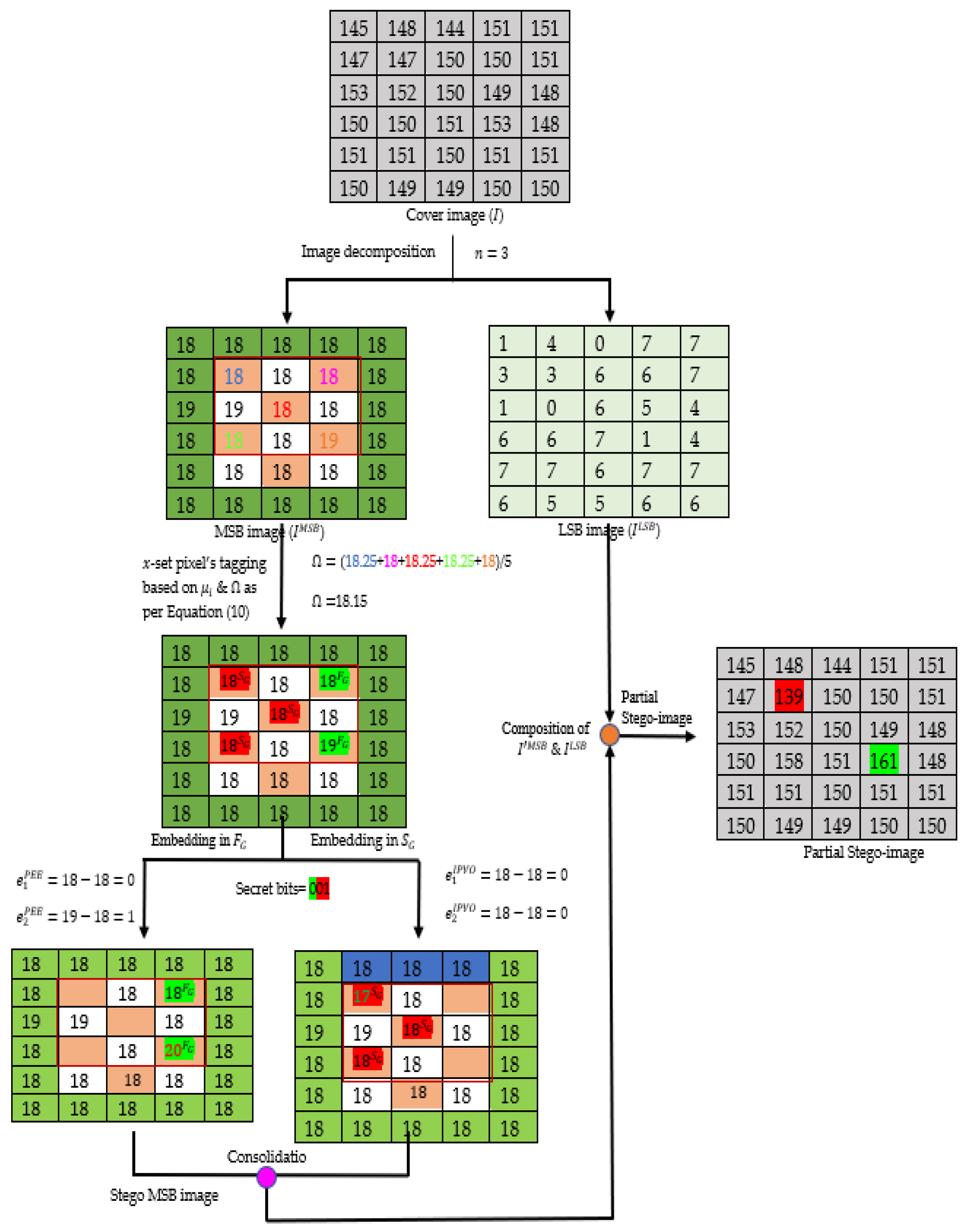
Embedding example: The proposed embedding process is illustrated using an example in Figure 3. The example considers a cover image ( I ) of 6 × 5 pixels, which is decomposed into two images ( I M S B and I L S B ) by considering n = 3 . Then, the I M S B image is represented in a checkboard pattern and divided into blocks of size 3 × 3 pixels, excluding border pixels (shown in blue). Next, embedding is carried out in the pixels of the blocks using adaptive embedding strategy in a phase-wise manner. In the first phase, the pixels shown in orange are used for embedding, followed by white ones in the second phase. Before each phase embedding, the pixels are segregated into two groups ( F G ,   S G ) using Equation (10). Here, the pixels grouped in the first group ( F G ) are tagged and background-colored green (for easy identification to readers), whereas the other pixels are tagged as S G and background-colored red. Then, the embedding is carried out on the pixels of both the groups using the adaptive embedding strategy. Since the first group ( F G ) has only two pixels (e.g., x 1 and x 2 ) of values 18 and 19, respectively, the embedding is done by using EP-PEE scheme. For this, two prediction errors ( e 1   P E E and e 2   P E E ) are calculated, such as e 1   P E E = x 1 [ μ 1 ]   and e 2   P E E = x 2 [ μ 2 ]   , where [ . ] gives a rounded-off value and the μ 1 and μ 2 represents the local moment of pixels x 1 and x 2 , respectively. Thus, the calculated values of [ μ 1 ]   and [ μ 2 ]   are 18 and 18, respectively. Therefore, e 1   P E E = 0 and e 2   P E E = 1 are obtained. Next, the errors are modified based on secret bits using Figure 2b. From Figure 2b, it is clear that the error pair (0, 1) can be expanded to either (0, 2) or (1, 2) based on the secret data bit value. Since the bit is ‘0’, the pair is expanded to (0, 2), which in turn modifies the pixels to 18 and 20. In this way, embedding is carried out in the F G . For embedding in the S G = ( 18 ,   18 ,   18 ) , the count of pixels in the group is checked, as it is 3, which means the embedding will be carried out using the EP-IPVO scheme. For this, two prediction errors ( e 1   I P V O and e 2   I P V O ) are calculated, such as e 1   I P V O = x s x t and e 2   I P V O = x u x v , where the value of x s ,   x t , x u , and x v are 18, 18, 18, and 18, respectively. Therefore, e 1   I P V O =0 and e 2   I P V O = 0 are obtained. Next, the errors are modified based on secret bits using Figure 2a. From Figure 2a, it is clear that the error pair (0, 0) can be expanded to either (0, 0), (−1, 0) or (0, −1) based on the secret data bits value. Since the bits are is ‘01’, the pair is expanded to (−1, 0) which in turn modifies the pixels to 17, 18, and 18. In this way, the embedding is carried out in the S G and the partial stego-image is obtained. In the next phase, the embedding in the white background pixels of the group can be performed in a similar manner. To avoid repetition of explanation, the same has not been repeated.

3.2. Secret Information Extraction and the Original Image Recovery Method

To recover the original image and extract the hidden information, the embedding phase is executed in the reverse manner. Here, firstly, auxiliary information, such as the value of n and location of the last embedding block ( B e n d ) is extracted from predefined LSBs of the border pixels of the cover image. Then, the image is decomposed into two images, I M S B and I L S B , using Equations (2) and (3) as in the embedding phase. Before extraction and recovery, first of all, I M S B is divided into blocks of 3 × 3 pixels and then the   y s e t pixels of each block are segregated into two groups. Next, the extraction and recovery of the pixels of each group are carried out based on the cardinality ( # ) of each group. More specifically, if cardinality ( # ) > 2 then two errors ( e 1   I P V O and e 2   I P V O ), after sorting the pixels of the group, are calculated using Equations (12) and (13), respectively. Next, the hidden information is extracted by receiving the contracted error pairs ( e 1   I P V O and e 2   I P V O ) after following Figure 2a by just reversing the arrow direction. Next, the minimum and the maximum pixels of the group are recovered using the following Equations (23) and (24), respectively:
x π ( 1 ) = x π ( 2 ) | e 1   I P V O |
x π ( N ) = x π ( N 1 ) + | e 2   I P V O |
In case the cardinality ( # ) is equal to 2, two errors ( e 1   P E E and e 2   P E E ) are calculated using Equations (16) and (17), respectively. Next, the hidden information is extracted by receiving the contracted error pairs ( e 1   P E E and e 2   P E E ) after following Figure 2b by just reversing the arrow direction. Next, the recovered pixels ( x 1 , x 2 ) of the group are obtained using the following Equations (25) and (26), respectively:
x 1 = [ μ 1 ] + e 1   P E E
x 2 = [ μ 2 ] + e 2   P E E
Otherwise, if cardinality ( # ) is equal to 1, that means the S-PEE rules of Table 1 are used for extracting the hidden information bit (   b 1 ) and recovering the pixel value.
After processing the y s e t pixels, x s e t pixels of I M S B are processed to get back the hidden information and recover them. This process is followed in a block-wise manner until all the hidden information is not extracted. Next, the compressed location map ( C L M ) is separated from the extracted hidden information and decompressed. The decompressed location map is then used to post-process the pixels of the image to reach their original values using Equation (27):
P l = { P l 1                       i f   P l = 0     a n d   L M ( l ) = 1 , P l + 1           i f   P l = M A X     a n d   L M ( l ) = 1 .  
where l is the number of the pixel scanned in the raster-scan order of the image I M S B . At the end, the resultant images I M S B and I L S B are composed to re-obtain the original cover image ( I ).
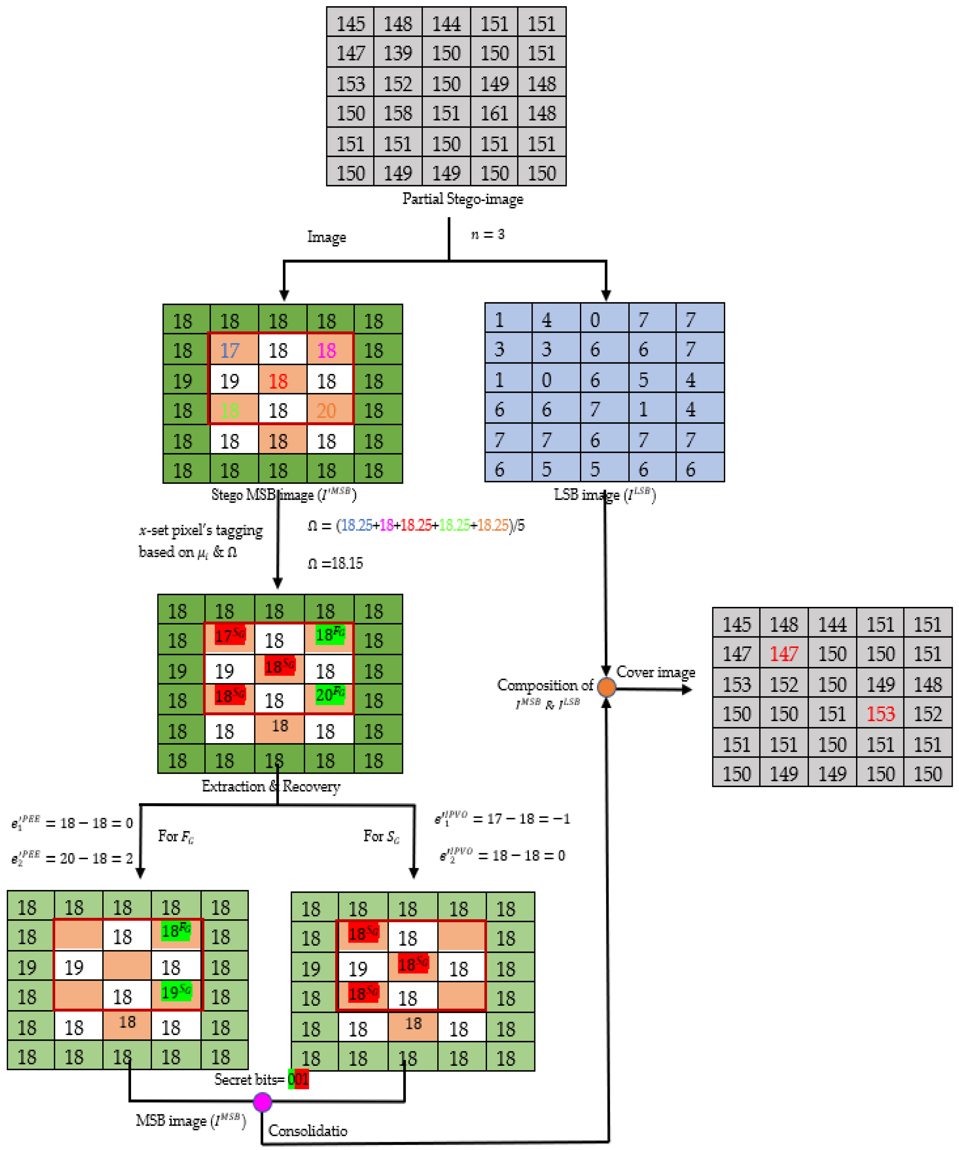
Extraction and recovering example: The proposed extraction and recovery process is illustrated using an example in Figure 4. The example considers a partial stego-image ( I ) of 6 × 5 pixels which is decomposed into two images ( I M S B and I L S B ) by considering n = 3 . Then, the I M S B image is represented in a checkboard pattern and divided into blocks of 3 × 3 pixels in size, excluding border pixels (shown in blue). Next, the pixels shown in orange are used for extraction and recovery. For this, the pixels are segregated into two groups ( F G ,   S G ) using Equation (10). Here, the pixels grouped in the first group ( F G ) are tagged and background-colored green (for easy identification to readers) whereas the other pixels are tagged as S G and background-colored red. Since the first group ( F G ) has only two pixels ( x 1 and x 2 ) of values 18 and 20, respectively, two prediction errors ( e 1   P E E and e 2   P E E ) are calculated, such as e 1   P E E = x 1 [ μ 1 ]   and e 2   P E E = x 2 [ μ 2 ]   , where [ . ] gives a rounded-off value and the μ 1 and μ 2 represent the local moment of pixel x 1 and x 2 , respectively. Thus, the calculated values of [ μ 1 ]   and [ μ 2 ]   are 18 and 18, respectively. Therefore, e 1   P E E =0 and e 2   P E E = 2 is obtained. Next, the error pair (0, 2) is contracted to (0, 1) by following Figure 2b and reversing the arrows of Figure 2b. Additionally, the hidden information obtained from the contraction is ‘0’. Next, the pixels ( x 1 and x 2 ) are recovered. Therefore, (18, 19) are received as the values of the pixel pair.
For extracting from S G = ( 17 ,   18 ,   18 ) , the count of pixels in the group is checked, as it is 3, meaning that the two prediction errors ( e 1   I P V O and e 2   I P V O ) are calculated, such as e 1   I P V O = x s x t and e 2   I P V O = x u x v   , where the value of x s ,   x t , x u , and x v are 17, 18, 18, and 18, respectively. Therefore, e 1   I P V O = 1 and e 2   I P V O = 0 are obtained. Next, the error pair ( 1, 0) is contracted to (0, 0) by following Figure 2a and reversing the arrows of Figure 2b. Additionally, the hidden information obtained from the contraction is ‘01’. Next, the pixels ( x π ( 1 ) and x π ( N ) ) are recovered. Therefore, (18, 18) are received as values of the minimum and maximum pixel pair. Thus, the hidden secret data bit ‘001’ and original image are both obtained without loss.

4. Experimental Results and Analysis

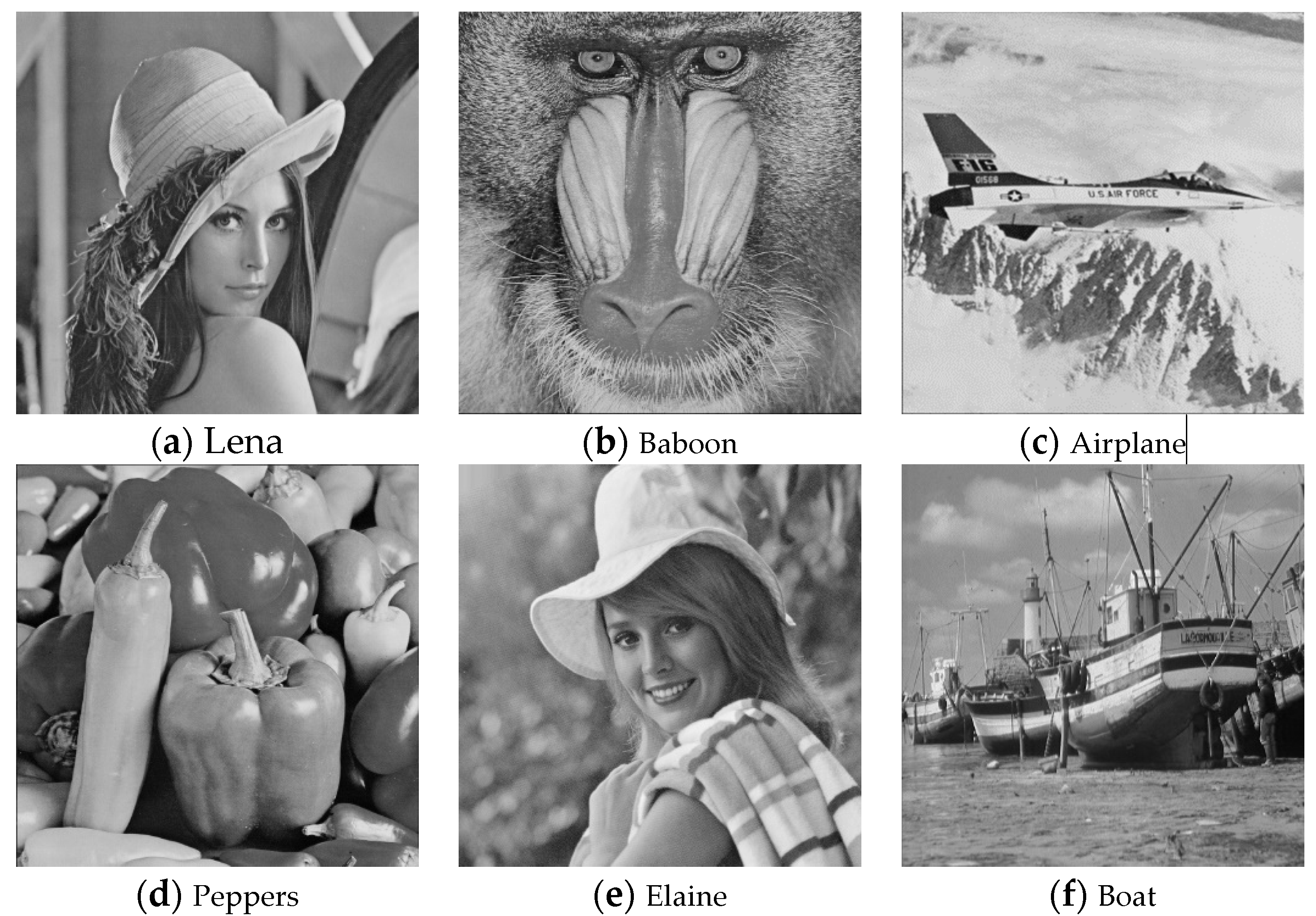
In this section, the performance of the proposed LM-RRDH scheme against some of the well-known spatial-domain-based RRDH schemes, such as Rajkumar et al. [28], SBDE [29], and TLE [30], is comparatively analyzed to avoid such problems. For experimental purposes, six standard grey-scale test images, each of size 512 × 512 pixels including Lena, Baboon, Airplane, Peppers, Elaine and Boat, were used, as shown in Figure 5. Further, the secret information stream was generated using the random function of MATLAB, as implementation was carried out using the same platform. The comparison of the performance was performed based on embedding capacity and image quality using peak signal-to-noise ratio (PSNR). The experimental results for robustness are not included for comparative performance analysis, as the LM-RRDH embeds the secret information into the MSB planes such as SBDE [29] and TLE [30], so it provides the same degree of robustness.
Two-dimensional (2D) line graphs have been used, as shown in Figure 6, to represent the embedding capacity (EC) versus PSNR experimental results. The 2D graphs present the comprehensive and thorough comparison of experimental results of the proposed LM-RRDH scheme against Rajkumar et al. [28], SBDE [29], and TLE [30]. It can be easily observed from Figure 6 that the proposed scheme has superior performance than all the other aforementioned spatial domain-based RRDH schemes. The main reasons behind the superior performance are (1) the more correlated grouping of the pixels based on their local moments, (2) adaptive selection of embedding strategy based on the cardinality of the group, and (3) usage of enhanced pairwise prediction-error-expansion-based embedding strategies. The more correlated groups of pixels help in generating sharper prediction error histograms, which lead to lesser shifting of pixels while increasing the expansion. Further, embedding the secret information using the best embedding strategy based on the type of group further helps in managing the trade-off between the EC and PSNR.
Furthermore, the enhanced-pairwise-embedding-strategies-based data hiding techniques assist in optimally exploiting the correlation in the form of prediction errors as well. This further helps in achieving superior performance. Therefore, it can be clearly stated that the LM-RRDH scheme provides improved embedding capacity and PSNR trade-off than the existing spatial-domain-based RRDH schemes, such as those of Rajkumar et al. [28], SBDE [29], and TLE [30], while maintaining the same degree of robustness.

5. Conclusions

In this paper, a local moment-driven robust reversible data-hiding (LM-RRDH) using pairwise embedding has been proposed. The proposed LM-RRDH scheme was a spatial domain based RRDH scheme which could provide the security to the hidden message against unintentional modifications. The proposed LM-RRDH first decomposed the image into LSB and MSB plane and embedded the secret data into the MSB image. For an efficient embedding, the proposed scheme divided the image into sub-blocks and segregated the pixels of each block to form highly correlated groups. Next, the secret data could be embedded into the pixels of each group by selecting an embedding strategy adaptively. As a result, the proposed LM-RRDH could limit the distortion to the human visual system while providing a decent embedding capacity. The experimental results have shown that the proposed LM-RRDH could provide better embedding capacity, while keeping a good PSNR, than the existing spatial-domain-based RRDH schemes. Further, the proposed LM-RRDH scheme provided the same level of robustness as the SBDE and TLE schemes. However, it can be vulnerable to various attacks when modifying higher significant bits. In future studies, a new scheme will be suggested to improve the embedding capacity while maintaining the same degree of robustness additionally.

Author Contributions

Conceptualization, Y.V.S. and S.K.; methodology, Y.V.S. and S.K.S.; visualization, S.K.; writing—Y.V.S. and K.-H.J.; writing—review and editing, Y.V.S., S.K.S., S.K. and K.-H.J. All authors have read and agreed to the published version of the manuscript.

Funding

This research was supported by the Brain Pool program funded by the Ministry of Science and ICT through the National Research Foundation of Korea (2019H1D3A1A01101687, 2021H1D3A2A01099390) and the Basic Science Research Program through the National Research Foundation of Korea (NRF) funded by the Ministry of Education (2021R1I1A3049788).

Institutional Review Board Statement

Not applicable.

Informed Consent Statement

Not applicable.

Data Availability Statement

The data can be made available on request to any of the authors.

Conflicts of Interest

The authors declare no conflict of interest.

References

  1. Kumar, R.; Saini, K.K.; Chand, S. A new steganography technique using snake scan ordering strategy. Int. J. Image 2013, 6, 25–32. [Google Scholar] [CrossRef] [Green Version]
  2. Kumar, R.; Chand, S.; Singh, S. An Improved Histogram-Shifting-Imitated Reversible Data Hiding based on HVS Characteristics. Multimed. Tools Appl. 2018, 77, 13445–13457. [Google Scholar] [CrossRef]
  3. Rai, A.K.; Kumar, N.; Kumar, R.; Om, H.; Chand, S.; Jung, K.-H. Intra-Block Correlation Based Reversible Data Hiding in Encrypted Images Using Parametric Binary Tree Labeling. Symmetry 2021, 13, 1072. [Google Scholar] [CrossRef]
  4. Kumar, R.; Chand, S. A reversible high capacity data hiding scheme using pixel value adjusting feature. Multimed. Tools Appl. 2016, 75, 241–259. [Google Scholar] [CrossRef]
  5. Malik, A.; Singh, S.; Kumar, R. Recovery based high capacity reversible data hiding scheme using even-odd embedding. Multimed. Tools Appl. 2018, 77, 15803–15827. [Google Scholar] [CrossRef]
  6. Kumar, R.; Chand, S.; Singh, S. A reversible high capacity data hiding scheme using combinatorial strategy. Int. J. Multimed. Intell. Secur. 2018, 3, 146–161. [Google Scholar] [CrossRef]
  7. Tian, J. Reversible data embedding using a difference expansion. IEEE Trans. Circuits Syst. Video Technol. 2003, 13, 890–896. [Google Scholar] [CrossRef] [Green Version]
  8. Alattar, A. Reversible watermark using the difference expansion of a generalized integer transform. IEEE Trans. Image Proc. 2014, 13, 1147–1156. [Google Scholar] [CrossRef]
  9. Thodi, D.M.; Rodriguez, J.J. Expansion embedding techniques for reversible watermarking. IEEE Trans. Image Process. 2007, 16, 721–730. [Google Scholar] [CrossRef]
  10. Sachnev, V.; Kim, H.J.; Nam, J.; Suresh, S.; Shi, Y.Q. Reversible watermarking algorithm using sorting and prediction. IEEE Trans. Circuits Syst. Video Technol. 2009, 19, 989–999. [Google Scholar] [CrossRef]
  11. Fallahpour, M. Reversible image data hiding based on gradient adjusted prediction. IEICE Electron. Exp. 2008, 5, 870–876. [Google Scholar] [CrossRef] [Green Version]
  12. Runwen, H.; Xiang, S. CNN prediction based reversible data hiding. IEEE Signal Process. Lett. 2021, 28, 464–468. [Google Scholar]
  13. Kumar, R.; Kim, D.S.; Lim, S.; Jung, K.H. High-Fidelity Reversible Data Hiding Using Block Extension Strategy. In Proceedings of the 34th International Technical Conference Circuits/Systems, Jeju, Korea, 23–26 June 2019; Volume 19, pp. 1–4. [Google Scholar]
  14. Kumar, R.; Kumar, N.; Jung, K.H. I-PVO based high capacity reversible data hiding using bin reservation strategy. Multimed. Tools Appl. 2020, 79, 22635–22651. [Google Scholar] [CrossRef]
  15. Ou, B.; Li, X.; Zhao, Y.; Ni, R.; Shi, Y.Q. Pairwise prediction-error expansion for efficient reversible data hiding. IEEE Trans. Image Process. 2013, 22, 5010–5021. [Google Scholar] [CrossRef]
  16. Kumar, R.; Jung, K.H. Enhanced pairwise IPVO-based reversible data hiding scheme using rhombus context. Inf. Sci. 2020, 536, 101–119. [Google Scholar] [CrossRef]
  17. Kaur, G.; Singh, S.; Rani, R.; Kumar, R.; Malik, A. High-quality reversible data hiding scheme using sorting and enhanced pairwise PEE. IET Image Process. 2021, 16, 1096–1110. [Google Scholar] [CrossRef]
  18. Ou, B.; Li, X.; Zhang, W.; Zhao, Y. Improving pairwise PEE via hybrid-dimensional histogram generation and adaptive mapping selection. IEEE Trans. Circuits Syst. Video Technol. 2018, 29, 2176–2190. [Google Scholar] [CrossRef]
  19. Kaur, G.; Singh, S.; Rani, R.; Kumar, R. A comprehensive study of reversible data hiding (RDH) schemes based on pixel value ordering (PVO). Arch. Comput. Methods Eng. 2021, 28, 3517–3568. [Google Scholar] [CrossRef]
  20. Zhaoxia, Y.; Xiang, Y.; Zhang, X. Reversible data hiding in encrypted images based on multi-MSB prediction and Huffman coding. IEEE Trans. Multimed. 2019, 22, 874–884. [Google Scholar]
  21. Puyang, Y.; Yin, Z.; Qian, Z. Reversible Data Hiding in Encrypted Images with Two-MSB Prediction. In Proceedings of the IEEE International Workshop on Information Forensics and Security (WIFS), Hong Kong, China, 11–13 December 2018; pp. 1–7. [Google Scholar]
  22. Puteaux, P.; Ong, S.Y.; KokSheik, W.; Puech, W. A survey of reversible data hiding in encrypted images—The first 12 years. J. Vis. Commun. Image Represent. 2021, 77, 103085. [Google Scholar] [CrossRef]
  23. Vleeschouwer, C.D.; Delaigle, J.F.; Macq, B. Circular interpretation of bijective transformations in lossless watermarking for media asset management. IEEE Trans. Multimed. 2003, 5, 97–105. [Google Scholar] [CrossRef]
  24. Ni, Z.C.; Shi, Y.Q.; Ansari, N.; Su, W.; Sun, Q.B.; Lin, X. Robust lossless image data hiding. Multimed. Expo. 2004, 3, 2199–2202. [Google Scholar]
  25. Ni, Z.C.; Shi, Y.Q.; Ansari, N.; Su, W.; Sun, Q.B.; Lin, X. Robust lossless image data hiding designed for semi-fragile image authentication. IEEE Trans. Circuits Syst. Video Technol. 2008, 18, 497–509. [Google Scholar]
  26. Zeng, X.T. A lossless robust data hiding scheme. Pattern Recognit. 2010, 43, 1656–1667. [Google Scholar] [CrossRef]
  27. Deng, C.; Gao, X.; Peng, H.; An, L.; Ji, F. Histogram modification based robust image watermarking approach. Int. J. Multimed. Intell. Secur. 2010, 1, 153–168. [Google Scholar] [CrossRef]
  28. Rajkumar, R.; Vasuki, A. Reversible and robust image watermarking based on histogram shifting. Clust. Comput. 2019, 22, 12313–12323. [Google Scholar] [CrossRef]
  29. Wang, W.; Ye, J.; Wang, T.; Wang, W. Reversible data hiding scheme based on significant-bit-difference expansion. IET Image Process. 2017, 11, 1002–1014. [Google Scholar] [CrossRef]
  30. Kumar, R.; Jung, K.H. Robust reversible data hiding scheme based on two-layer embedding strategy. Inf. Sci. 2020, 512, 96–107. [Google Scholar] [CrossRef]
  31. Zong, T.; Xiang, Y.; Natgunanathan, I.; Guo, S.; Zhou, W.; Beliakov, G. Robust histogram shape-based method for image watermarking. IEEE Trans. Circuits Syst. Video Technol. 2015, 25, 717–729. [Google Scholar] [CrossRef]
  32. Hu, X.; Wang, D.A. Histogram based algorithm robust to geometric distortions. In Proceedings of the International Conference on Electrical, Computer Engineering and Electronics, Jinan, China, 29–31 May 2015. [Google Scholar]
  33. Golabi, S.; Helfroush, M.S.; Danyali, H. Non-unit mapped radial moments platform for robust, geometric invariant image watermarking and reversible data hiding. Inf. Sci. 2018, 447, 104–116. [Google Scholar] [CrossRef]
  34. Bao, Z.; Luo, X.; Zhang, Y.; Yang, C.; Liu, F. A Robust Image Steganography on Resisting JPEG Compression with No Side Information. IETE Tech. Rev. 2018, 35, 4–13. [Google Scholar] [CrossRef] [Green Version]
  35. Kumar, N.; Kumar, R.; Caldelli, R. Local Moment Driven PVO Based Reversible Data Hiding. IEEE Signal Process. Lett. 2021, 28, 1335–1339. [Google Scholar] [CrossRef]
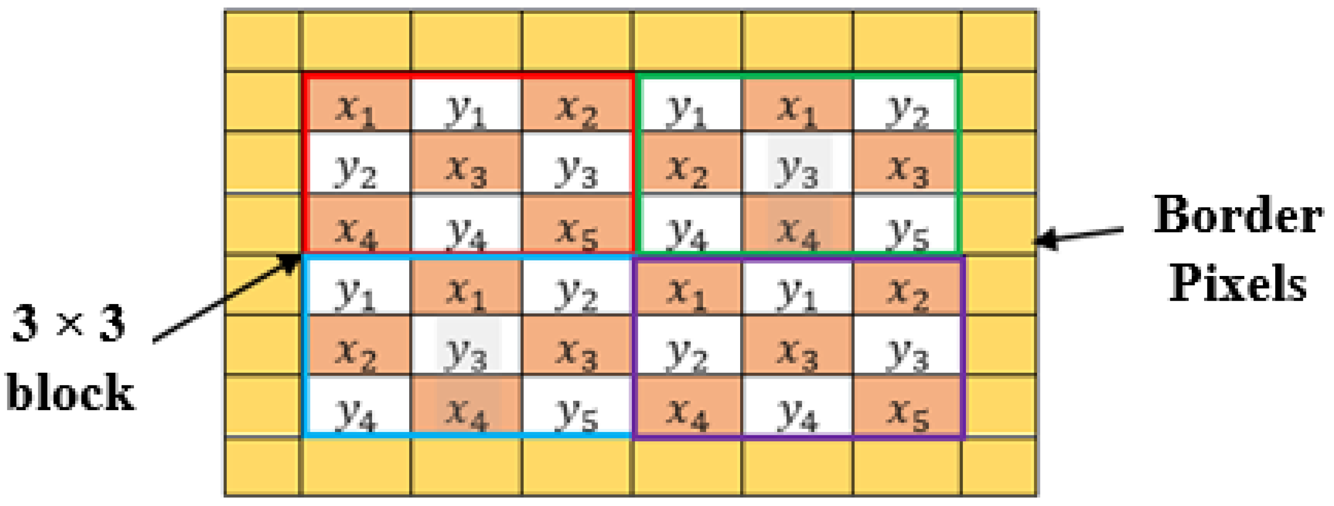
Figure 1. Checkboard representation of image.
Applsci 12 11826 g001
Figure 2. Prediction error pair modification/mapping. (a) Error pair expansion for EP-IPVO strategy. (b) Error pair expansion for EP-PEE strategy.
Applsci 12 11826 g002
Figure 3. The proposed LM-RRDH embedding example.
Applsci 12 11826 g003
Figure 4. The proposed LM-RRDH extraction and recovery example.
Applsci 12 11826 g004
Figure 5. Cover images, each of size 512 × 512 pixels.
Applsci 12 11826 g005
Figure 6. PSNR vs. EC evaluation for the test images [28,29,30].
Applsci 12 11826 g006
Table 1. S-PEE extraction and recovery rules.
x 1 [ μ 1 ] < 2 2 101>1
x i , j x 1 + 1 x 1 + 1 x 1 x 1 x 1 1 x 1 1
b 1 -0101-
Publisher’s Note: MDPI stays neutral with regard to jurisdictional claims in published maps and institutional affiliations.