
Deposition of Different Metallic Coatings as Repair Materials for Concrete by Using a Twin-Wire Arc Thermal Spray Process


Abstract
:1. Introduction
2. Materials and Methods
2.1. Deposition of the Coatings on the Concrete Surface
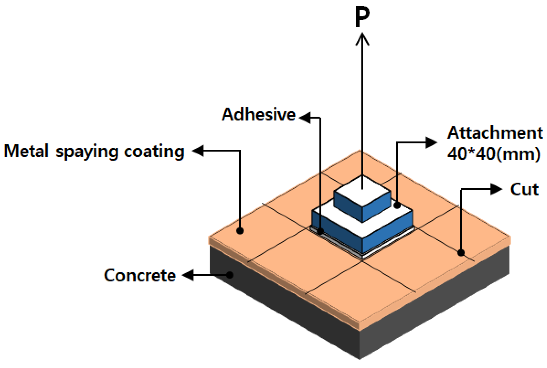
2.2. Bond Adhesion Measurement
2.3. Characterization of Coatings and Corrosion Products
2.4. Performance Evaluation of the Coatings as Repair Materials
2.4.1. Water Permeability
2.4.2. Carbonation Resistance
2.4.3. NaCl Resistance
3. Results and Discussion
3.1. Characterization of Coatings
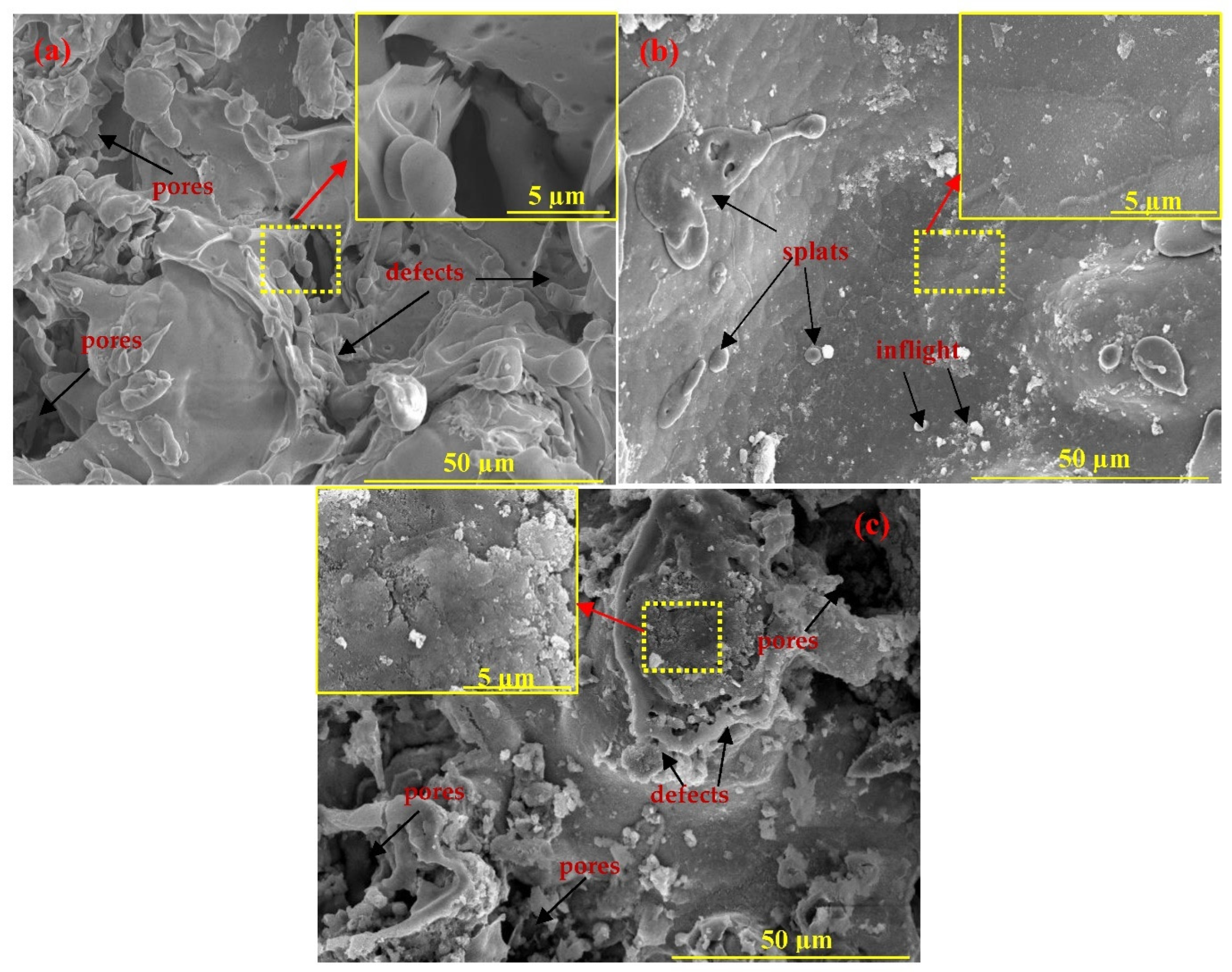
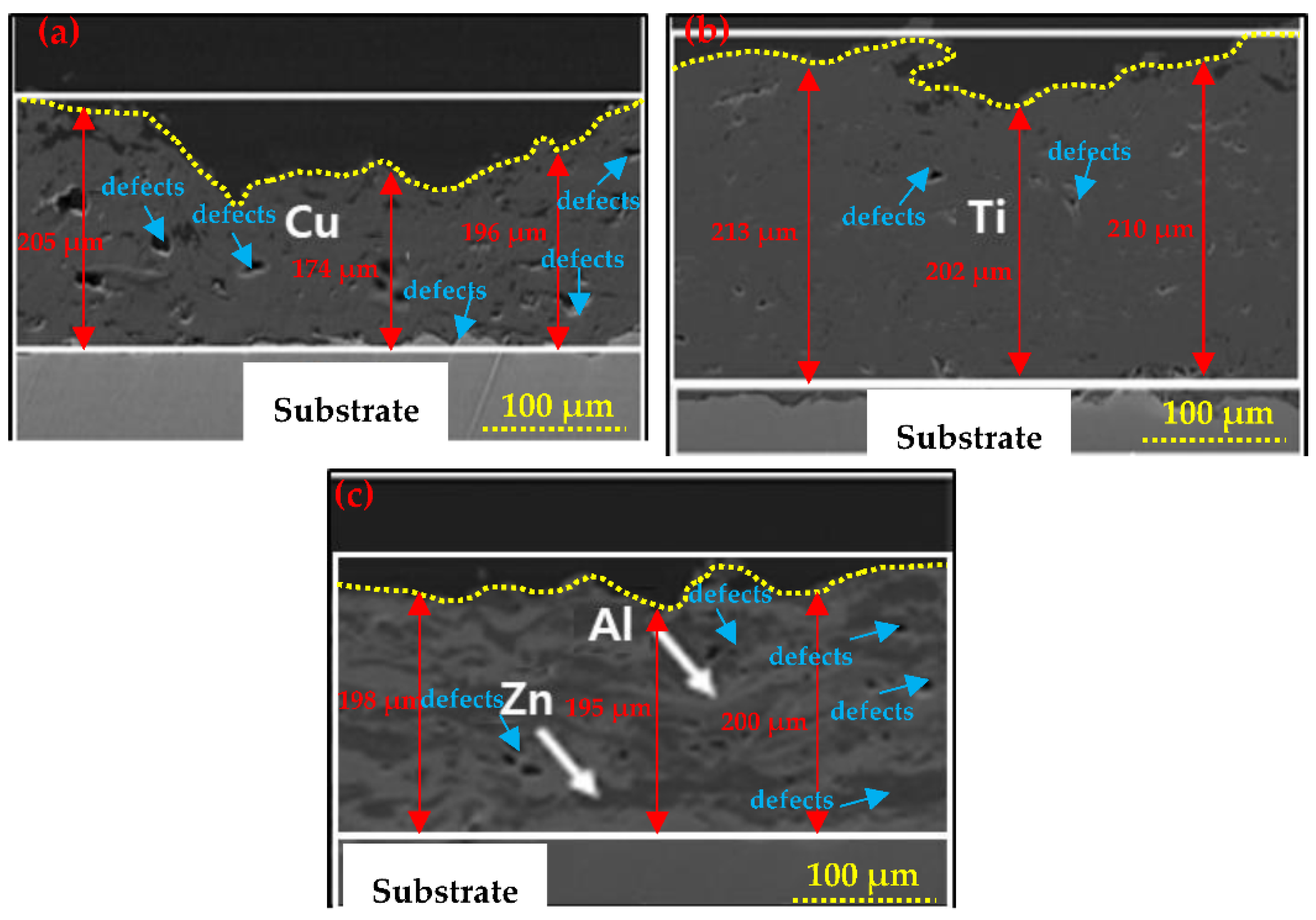
3.1.1. SEM of the Coatings
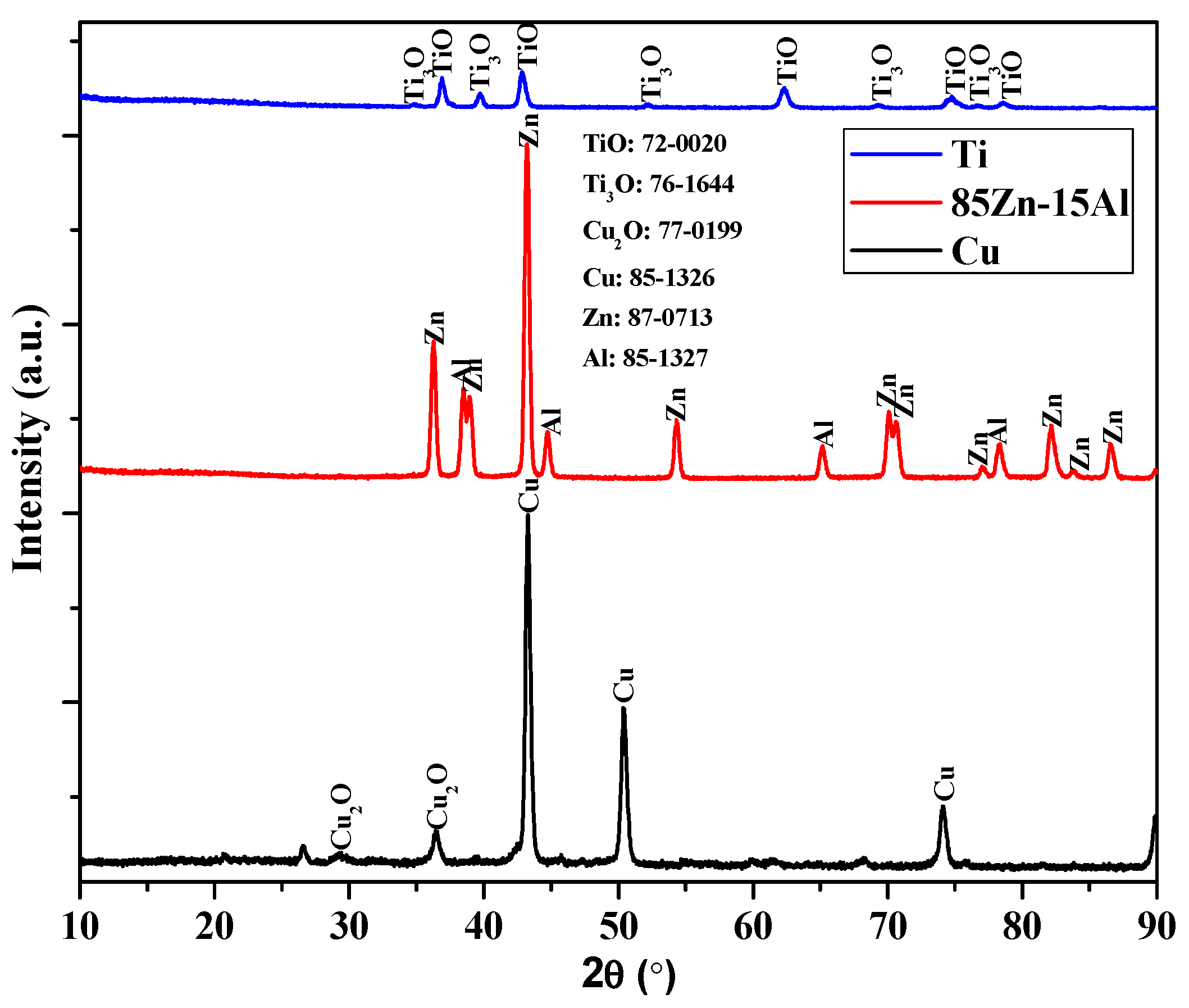
3.1.2. XRD of the Coatings
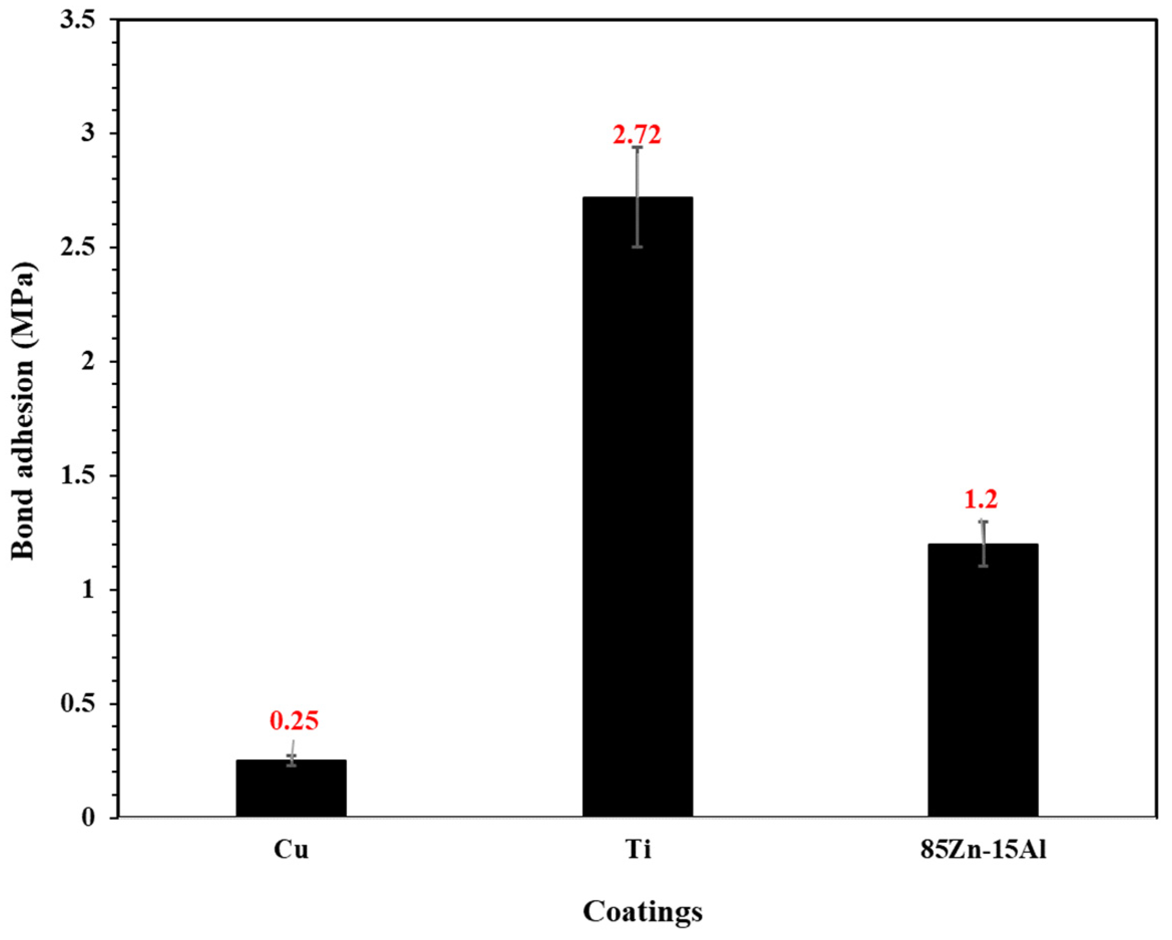
3.1.3. Bond Adhesion Measurement
3.2. Performance Evaluation of the Coatings
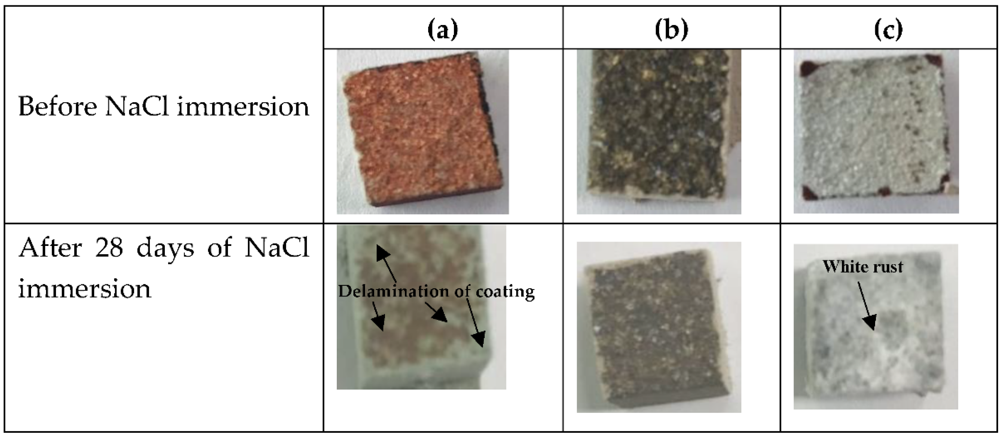
3.2.1. NaCl Immersion Test
3.2.2. Carbonation Resistance
3.2.3. Water Permeability
3.3. Characterization of Corrosion Products after 28 Days of Immersion in a 5% NaCl Solution
3.3.1. SEM of Corrosion Products
3.3.2. XRD of the Corrosion Products
4. Conclusions
- The Cu and 85Zn-15Al coatings deposited through a twin-wire arc thermal spray process exhibited severe defect formation and porosity, while Ti showed a dense morphology with 1.69% porosity;
- Cu and Ti coatings were partially oxidized owing to their high melting points, as confirmed by XRD results;
- The Cu coating showed the lowest bond adhesion, attributed to the defects and porosity, which led to a reduction in the anchoring properties of the substrate. By contrast, the Ti coating exhibited 11 times higher bond adhesion than the Cu coating;
- The Cu coating was susceptible to the NaCl solution, as delamination was observed on the concrete surface after 28 days of immersion, whereas the 85Zn-15Al coating formed a layer of white rust. However, NaCl did not affect the properties of the Ti coating;
- The Ti coating exhibited around 1.5–2 times lesser carbonation penetration depth after four and eight weeks of exposure than those of the Cu and 85Zn-15Al coatings;
- Ti could be an alternative to cement-based repair materials, polymer-modified materials, etc., as Ti-based repair materials deposited through twin-wire arc thermal spray processes extend the service life of buildings and infrastructure.
Author Contributions
Funding
Institutional Review Board Statement
Informed Consent Statement
Data Availability Statement
Conflicts of Interest
References
- Napoli, A.; de Felice, G.; De Santis, S.; Realfonzo, R. Bond behaviour of Steel Reinforced Polymer strengthening systems. Compos. Struct. 2016, 152, 499–515. [Google Scholar] [CrossRef]
- Climent, M.; Ortega, J.; Sánchez, I. Cement mortars with fly ash and slag—Study of their microstructure and resistance to salt ingress in different environmental conditions. In Concrete Repair, Rehabilitation and Retrofitting III, Proceedings of the 3rd International Conference on Concrete Repair, Rehabilitation and Retrofitting (ICCRRR 2012), Cape Town, South Africa, 3–5 September 2012; CRC Press: London, UK, 2012; pp. 3–5. [Google Scholar]
- Alexander, M.G.; Beushausen, H.-D.; Dehn, F.; Moyo, P. Concrete Repair, Rehabilitation and Retrofitting III: 3rd International Conference on Concrete Repair, Rehabilitation and Retrofitting, ICCRRR-3, Cape Town, South Africa, 3–5 September 2012; CRC Press: London, UK, 2012. [Google Scholar]
- Luković, M.; Šavija, B.; Dong, H.; Schlangen, E.; Ye, G. Micromechanical study of the interface properties in concrete repair systems. J. Adv. Concr. Technol. 2014, 12, 320–339. [Google Scholar] [CrossRef] [Green Version]
- Fathy, A.; Zhu, H.; Kohail, M. Factors affecting the fresh-to-hardened concrete repair system. Constr. Build. Mater. 2022, 320, 126279. [Google Scholar] [CrossRef]
- Qian, J.; You, C.; Wang, Q.; Wang, H.; Jia, X. A method for assessing bond performance of cement-based repair materials. Constr. Build. Mater. 2014, 68, 307–313. [Google Scholar] [CrossRef]
- Zhou, J.; Ye, G.; Schlangen, E.; van Breugel, K. Modelling of stresses and strains in bonded concrete overlays subjected to differential volume changes. Theor. Appl. Fract. Mech. 2008, 49, 199–205. [Google Scholar] [CrossRef]
- Hassan, K.; Brooks, J.; Al-Alawi, L. Compatibility of repair mortars with concrete in a hot-dry environment. Cem. Concr. Compos. 2001, 23, 93–101. [Google Scholar] [CrossRef]
- Song, X.; Song, X.; Liu, H.; Huang, H.; Anvarovna, K.G.; Ugli, N.A.D.; Huang, Y.; Hu, J.; Wei, J.; Yu, Q. Cement-based repair materials and the interface with concrete substrates: Characterization, evaluation and improvement. Polymers 2022, 14, 1485. [Google Scholar] [CrossRef]
- Shaw, M. Guide to the Concrete Repair European Standards BS EN 1504 Series; Sika Limited: Watchmead, Welwyn Garden City, Hertfordshire, UK, 2019. [Google Scholar]
- El-Hawary, M.; Al-Khaiat, H.; Fereig, S. Performance of epoxy-repaired concrete in a marine environment. Cem. Concr. Res. 2000, 30, 259–266. [Google Scholar] [CrossRef]
- Hunkeler, F. The resistivity of pore water solution—A decisive parameter of rebar corrosion and repair methods. Constr. Build. Mater. 1996, 10, 381–389. [Google Scholar] [CrossRef]
- Basunbul, I.; Gubati, A.; Al-Sulaimani, G.; Baluch, M. Repaired reinforced concrete beams. Mater. J. 1990, 87, 348–354. [Google Scholar]
- Saccani, A.; Magnaghi, V. Durability of epoxy resin-based materials for the repair of damaged cementitious composites. Cem. Concr. Res. 1999, 29, 95–98. [Google Scholar] [CrossRef]
- Ariffin, N.F.; Hussin, M.W.; Sam, A.R.M.; Bhutta, M.A.R.; Khalid, N.H.A.; Mirza, J. Strength properties and molecular composition of epoxy-modified mortars. Constr. Build. Mater. 2015, 94, 315–322. [Google Scholar] [CrossRef] [Green Version]
- Liu, Y.; Wang, F.; Liu, M.; Hu, S. A microstructural approach to adherence mechanism of cement and asphalt mortar (CA mortar) to repair materials. Constr. Build. Mater. 2014, 66, 125–131. [Google Scholar] [CrossRef]
- Abu-Tair, A.; Rigden, S.; Burley, E. Testing the bond between repair materials and concrete substrate. Mater. J. 1996, 93, 553–558. [Google Scholar]
- Lee, H.-S.; Park, J.-H.; Singh, J.K.; Ismail, M.A. Protection of reinforced concrete structures of waste water treatment reservoirs with stainless steel coating using arc thermal spraying technique in acidified water. Materials 2016, 9, 753. [Google Scholar] [CrossRef] [Green Version]
- Lee, H.-S.; Park, J.-H.; Singh, J.K.; Ismail, M.A. Deposition of coating to protect waste water reservoir in acidic solution by arc thermal spray process. Adv. Mater. Sci. Eng. 2018, 2018, 4050175. [Google Scholar] [CrossRef] [Green Version]
- Park, J.-H.; Singh, J.K.; Lee, H.-S. Ozone resistance, water permeability, and concrete adhesion of metallic films sprayed on a concrete structure for advanced water purification. Coatings 2017, 7, 41. [Google Scholar] [CrossRef] [Green Version]
- Al-Negheimish, A.; Hussain, R.R.; Alhozaimy, A.; Singh, D. Corrosion performance of hot-dip galvanized zinc-aluminum coated steel rebars in comparison to the conventional pure zinc coated rebars in concrete environment. Constr. Build. Mater. 2021, 274, 121921. [Google Scholar] [CrossRef]
- Lee, H.-S.; Singh, J.K.; Ismail, M.A.; Bhattacharya, C.; Seikh, A.H.; Alharthi, N.; Hussain, R.R. Corrosion mechanism and kinetics of Al-Zn coating deposited by arc thermal spraying process in saline solution at prolong exposure periods. Sci. Rep. 2019, 9, 3399. [Google Scholar] [CrossRef] [Green Version]
- Lee, H.-S.; Kwon, S.-J.; Singh, J.K.; Ismail, M.A. Influence of Zn and Mg alloying on the corrosion resistance properties of Al coating applied by arc thermal spray process in simulated weather solution. Acta Metall. Sin. 2018, 31, 591–603. [Google Scholar] [CrossRef] [Green Version]
- Lee, H.-S.; Park, J.-h.; Singh, J.K.; Choi, H.-J.; Mandal, S.; Jang, J.-M.; Yang, H.-M. Electromagnetic shielding performance of carbon black mixed concrete with Zn–Al metal thermal spray coating. Materials 2020, 13, 895. [Google Scholar] [CrossRef] [PubMed] [Green Version]
- Choe, H.-B.; Lee, H.-S.; Shin, J.-H. Experimental study on the electrochemical anti-corrosion properties of steel structures applying the arc thermal metal spraying method. Materials 2014, 7, 7722–7736. [Google Scholar] [CrossRef] [PubMed]
- Lee, H.-S.; Singh, J.K.; Park, J.H. Pore blocking characteristics of corrosion products formed on Aluminum coating produced by arc thermal metal spray process in 3.5 wt.% NaCl solution. Constr. Build. Mater. 2016, 113, 905–916. [Google Scholar] [CrossRef]
- Steffens, H.-D.; Babiak, Z.; Wewel, M. Recent developments in arc spraying. IEEE Trans. Plasma Sci. 1990, 18, 974–979. [Google Scholar] [CrossRef]
- Malek, M.H.A.; Saad, N.H.; Abas, S.K.; Shah, N.B.M. Critical process and performance parameters of thermal arc spray coating. Int. J. Mater. Eng. Innov. 2014, 5, 12–27. [Google Scholar] [CrossRef]
- Davis, J.R. Surface Engineering for Corrosion and Wear Resistance; ASM International: Almere, The Netherlands, 2001. [Google Scholar]
- Korea Standard KS F4716; Cement Filling Compound for Surface Preparation Korean Agency for Technology and Standards (KATS). Korean Agency for Technology and Standards: Eumseong County, Korea, 2001.
- Lee, H.-S.; Singh, J.K. Deposition and corrosion studies of plasma arc thermal sprayed Zn and 85Zn–15Al films on steel surface. J. Mater. Sci. 2022, 57, 19650–19665. [Google Scholar] [CrossRef]
- Korea Standard KS F4930; Penetrating Water Repellency of Liquid Type for Concrete Surface Application. Korea Standards Association: Seoul, Korea, 2002.
- Korea Standard KS F2584; Standard Test Method for Accelerated Carbonation of Concrete. Korea Standards Association: Seoul, Korea, 2005.
- Jang, J.-M.; Lee, H.-S.; Singh, J.K. Electromagnetic Shielding Performance of Different Metallic Coatings Deposited by Arc Thermal Spray Process. Materials 2020, 13, 5776. [Google Scholar] [CrossRef]
- Sharifahmadian, O.; Salimijazi, H.; Fathi, M.; Mostaghimi, J.; Pershin, L. Study of the antibacterial behavior of wire arc sprayed copper coatings. J. Therm. Spray Technol. 2013, 22, 371–379. [Google Scholar] [CrossRef]
- Deshpande, S.; Sampath, S.; Zhang, H. Mechanisms of oxidation and its role in microstructural evolution of metallic thermal spray coatings—Case study for Ni–Al. Surf. Coat. Technol. 2006, 200, 5395–5406. [Google Scholar] [CrossRef]
- Cheng, X.; Roscoe, S.G. Corrosion behavior of titanium in the presence of calcium phosphate and serum proteins. Biomaterials 2005, 26, 7350–7356. [Google Scholar] [CrossRef]
- Pouilleau, J.; Devilliers, D.; Garrido, F.; Durand-Vidal, S.; Mahé, E. Structure and composition of passive titanium oxide films. Mater. Sci. Eng. B 1997, 47, 235–243. [Google Scholar] [CrossRef]
- Xie, M. Study of bond strength of composite and concrete interface in the rehabilitation of concrete structures using polymer composites. In Proceedings of the ICCM-X Vol. III: Process. Manufacturing; Woodhead Publishing: Vancouver, BC, Canada, 1995; pp. 613–620. [Google Scholar]
- Karbhari, V.; Engineer, M. Investigation of bond between concrete and composites: Use of a peel test. J. Reinf. Plast. Compos. 1996, 15, 208–227. [Google Scholar] [CrossRef]
- Shrestha, S.; Sturgeon, A. Use of advanced thermal spray processes for corrosion protection in marine environments. Surf. Eng. 2004, 20, 237–243. [Google Scholar] [CrossRef]
- Zhu, Z.; Chu, H.; Guo, M.-Z.; Zhang, Y.; Song, Z.; Jiang, L. Anti-microbial corrosion performance of concrete treated by Cu2O electrodeposition: Influence of different treatment parameters. Cem. Concr. Compos. 2021, 123, 104195. [Google Scholar] [CrossRef]
- Ishikawa, T.; Matsumoto, K.; Yasukawa, A.; Kandori, K.; Nakayama, T.; Tsubota, T. Influence of metal ions on the formation of artificial zinc rusts. Corros. Sci. 2004, 46, 329–342. [Google Scholar] [CrossRef]
- Amanian, S.; Naderi, R.; Mahdavian, M. The Role of an In-Situ Grown Zn-Al Layered Double Hydroxide Conversion Coating in the Protective Properties of Epoxy Coating on Galvanized Steel. J. Electrochem. Soc. 2022, 169, 031511. [Google Scholar] [CrossRef]


| Sample ID | Elements (wt.%) | ||||
|---|---|---|---|---|---|
| Cu | Ti | Zn | Al | O | |
| Cu | 94.84 | - | - | - | 5.16 |
| Ti | - | 80.15 | - | - | 19.85 |
| 85Zn-15Al | - | - | 84.13 | 13.24 | 2.63 |
| Coatings | Vf (%) | |||||
|---|---|---|---|---|---|---|
| Cu | Cu2O | Zn | Al | TiO | Ti3O | |
| Cu | 80.96 | 19.04 | - | - | - | - |
| Ti | - | - | - | - | 73.95 | 26.05 |
| 85Zn-15Al | - | - | 86.25 | 13.75 | - | - |
| Sample ID | 4 Weeks | 8 Weeks |
|---|---|---|
| Concrete | 14.4 mm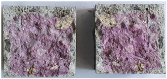 | 18 mm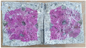 |
| Cu | 14.8 mm | 20.2 mm |
| Ti | 9.2 mm | 12.5 mm |
| 85Zn-15Al | 13.3 mm | 21.2 mm |
| Coatings | Weight of Samples before Water Immersion (g) | Weight of Samples after Immersion in Water (g) | Amount of Water Permeated (g) = Weight of Samples after Water Immersion—Weight of Samples before Water Immersion | Permeability Ratio |
|---|---|---|---|---|
| Concrete | 802.3 | 825.2 | 22.9 | - |
| Cu | 785.2 | 798.0 | 12.8 | 0.56 |
| Ti | 885.1 | 896.7 | 11.6 | 0.50 |
| 85Zn-15Al | 815.4 | 827.8 | 12.4 | 0.54 |
| Coatings | Elements (wt.%) | |||||||
|---|---|---|---|---|---|---|---|---|
| Cu | Ti | Zn | Al | O | Na | Cl | Ca | |
| Cu | 46.17 | 0 | 0 | 0 | 5.26 | 24.38 | 22.96 | 1.24 |
| Ti | 0 | 77.01 | 0 | 0 | 22.40 | 0.39 | 0.21 | 0 |
| 85Zn-15Al | 0 | 0 | 41.48 | 10.97 | 26.70 | 12.99 | 7.86 | 0 |
| Coatings | Vf (%) | ||||||||
|---|---|---|---|---|---|---|---|---|---|
| CuO | Cu2O | Zn | Al | TiO | Ti3O | NaCl | CuCl2(H2O)2 | Zn5(OH)8Cl2·H2O | |
| Cu | 18.60 | 20.98 | - | - | - | - | 11.50 | 48.92 | - |
| Ti | - | - | - | - | 78.54 | 21.46 | - | - | - |
| 85Zn-15Al | - | - | 45.31 | 12.95 | - | - | 10.65 | - | 31.09 |
Publisher’s Note: MDPI stays neutral with regard to jurisdictional claims in published maps and institutional affiliations. |
© 2022 by the authors. Licensee MDPI, Basel, Switzerland. This article is an open access article distributed under the terms and conditions of the Creative Commons Attribution (CC BY) license (https://creativecommons.org/licenses/by/4.0/).
Share and Cite
Kim, S.Y.; Lee, H.-S.; Park, J.-H. Deposition of Different Metallic Coatings as Repair Materials for Concrete by Using a Twin-Wire Arc Thermal Spray Process. Appl. Sci. 2022, 12, 11874. https://doi.org/10.3390/app122311874
Kim SY, Lee H-S, Park J-H. Deposition of Different Metallic Coatings as Repair Materials for Concrete by Using a Twin-Wire Arc Thermal Spray Process. Applied Sciences. 2022; 12(23):11874. https://doi.org/10.3390/app122311874
Chicago/Turabian StyleKim, Sang Youl, Han-Seung Lee, and Jin-Ho Park. 2022. "Deposition of Different Metallic Coatings as Repair Materials for Concrete by Using a Twin-Wire Arc Thermal Spray Process" Applied Sciences 12, no. 23: 11874. https://doi.org/10.3390/app122311874