Abstract
Development of U-type pre-stressed girders has been attempted to increase the length of I-type girders in South Korea. However, a length of 30 m or less is common because the self-weight, according to the post-tension method, is large. In this study, the pre-tension method was applied without limiting the post-tension method to induce a reduction in self-weight and in the materials used because of the decrease in the cross section. In addition, the authors proposed an application of an on-site pre-tensioning method using the internal reaction arm of a U-type girder. A pre-stressed concrete U-type girder bridge is composed of a concrete deck slab and a composite section. Structural performance characteristics, such as resistance and rigidity, were improved compared to those of the PSC I-type girders. Construction safety is also improved in the manufacturing and installation stages, and the elongation ratio is reduced because of the reduction in the weight of the girders. Therefore, it is possible to ensure the aesthetic landscape and economic efficiency of bridges. As a result, it is expected that efficient construction will be possible with high-quality factory-made and cast-in-place members. In this study, the pre-tension method is introduced in the field, and the analytical performance of the anchoring block used for tension is verified.
1. Introduction
Bridges are structures installed to conveniently pass sections that impede movement, such as rivers and valleys. As of December 2021, 37,078 bridges have been installed and operated in South Korea [1]. Within the 2022 budget of the Ministry of Land, Infrastructure and Transport, the SOC (Social Overhead Capital) budget is KRW 22,791.3 billion, of which the budget for the road sector is approximately USD 580 M, an 11% increase from the previous year, and the demand for bridge construction is expected to increase [2].
As a result of analyzing the current status by road and superstructure types among domestic bridges according to the “Road Bridge and Tunnel Status Report,” it is evident that pre-stressed concrete (herein so called PSC) bridges have been widely constructed due to their lower construction and maintenance costs compared to steel bridges [1]. PSC bridges are also widely used because of the convenience of their management (9643 locations as of December 2021, accounting for approximately 26%) [1]. Based on the results of the analysis of bridge superstructure types, the overall share of the Rahman and slab superstructure type is approximately 24%, and the PSC I-type girder has an occupancy of approximately 22% [2].
Among the superstructure types, the PSC I-type girder has gradually increased in share owing to improvements in design and construction methods over the past 10 years. As such, the Rhamen superstructure type and PSC I-type girder, used in road bridges and other applications, comprise a very large market, and many related technologies are being developed. The Rhamen bridge has the advantage that there is no need for defect repair, such as not requiring any movement or bridge support. However, their application in long-span bridges is limited. In addition, PSC I-type girders have only recently been introduced in South Korea, and they have disadvantages such as complicated structure, ambiguity of design standards, difficulty in construction (i.e., overturning due to the cross-sectional shape), and low economic feasibility due to increases in material cost [3,4,5,6,7,8].
Guo et al. introduced a fully composite beam consisting of U-shaped steel girders and angle connectors. They experimentally evaluated the beam and showed that it improved flexural behavior [9]. Svoboda et al. strengthened and rehabilitated U-shaped reinforced concrete bridges using post-tensioning with cable ducts. They concluded that post-tensioning with cable ducts is a highly efficient method for strengthening existing bridges to increase their load-bearing capacity [10]. Zhang et al. mentioned that U-shaped girders have been widely accepted for their adaptability owing to the difference between U-shaped girders and conventional section girders [11].
Currently, modern society is entering a technology-intensive era owing to the overall decline in labor productivity, but the construction market remains labor-intensive. As a result, it can be predicted that the construction market will change from labor-intensive to technology-intensive, and it will change from conventional on-site production-dependent technology to on-site assembly method construction technology. In response to this trend, the PSC U-type girder construction method presented in this article introduces a pre-tensioning method that can be manufactured on-site using factory-made anchoring blocks, cross-beams, and internal reaction arms, which constitute a structural stress disturbance zone. A schematic overview of the PSC U-type girder is shown in Figure 1 [12]. We aim to develop a technology that improves the quality and constructability of structures and increases the economic effect by optimizing on-site and factory production.
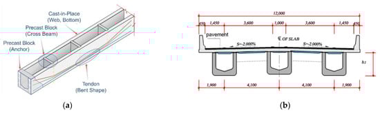
Figure 1.
Configuration and conceptual diagram of the pre-tensioned U-type girder for the (a) unit girder (precast and cast-in-place) manufacturing method and (b) closed bridge section.
The PSC U-type cross-section girder bridge is composed of a concrete slab and a composite cross-section. It is a highly efficient and economical bridge because it is possible to increase its safety in the construction stage, reduce the height ratio by reducing its own weight, and secure the aesthetic landscape of the bridge. Additionally, it is possible to improve the construction quality and efficiency of high-quality factory-made members and integrated casting at the site. Figure 2 shows how the U-type girder was manufactured by tensioning (a) using the anchoring block for tension and the internal reaction arm and (b) pouring-curing the concrete under tension [12].
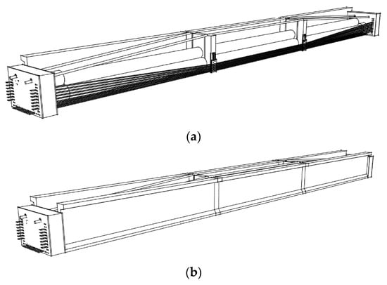
Figure 2.
Pre-tensioning mechanism using internally placed concrete piles as a reaction arm and forces applied through strands to anchor blocks for (a) Arrangement of anchor block-hydraulic cylinder-internal reaction arm (b) After concrete pouring and curing.
2. Background
Concrete, as a structural material, is known to be strong in compression, but weak in tension. When bending occurs in the beam owing to an external force, a compressive force is generated on the upper surface of the beam, and a tensile force is generated on the lower surface of the beam. Therefore, concrete with a weakness in tension is not suitable for use as a flexural member because it cracks and breaks at the lower surface, where the tensile force is generated. To compensate for the disadvantages of concrete, reinforcing bars are placed inside the concrete to strengthen the structure against tension [13].
However, a reinforced concrete structure also requires a larger cross-section as the span increases, and accordingly, its own weight gradually increases, making it an inefficient structure for long spans. Moreover, it is very difficult to avoid deflection of the structure caused by the working load of the vehicle and the occurrence of cracks owing to the tensile force [14,15].
To compensate for the limitations and disadvantages of the reinforced concrete structure, a steel strand was placed in the concrete such that no tensile force was generated in the concrete, and a compressive force was applied to the concrete by pulling and fixing it strongly from both ends. Pre-stressed concrete (PSC) is a concrete structure that is restrained. Reinforced concrete structure is a concept that compensates for these shortcomings by reinforcing concrete that is weak in tension with reinforcing bars. Introducing the pre-stress introduces the compressive force of the beam caused by the pre-stress to be greater than the tensile force on the lower surface of the beam generated by the external force; thus, the tensile force is not generated in the concrete when an external force is applied [7,16]. An overview of this procedure is shown in Figure 3 [16].
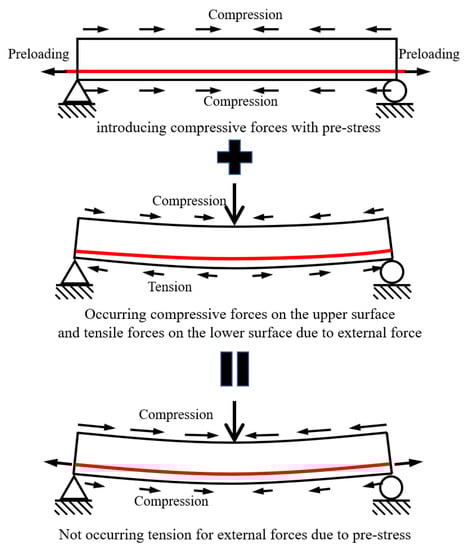
Figure 3.
Pre-stressed concrete concept.
In bridge construction, pre-stressed concrete girders are constructed according to the method of introducing pre-stressing. They are divided into tension and pretension methods. The post-tension method introduces a tension force into the concrete structure as a reaction force by inserting a tension material, which is a compression material, into the buried sheath pipe (steel duct, etc.) after the concrete is cured. After placing and stretching the tension member, the concrete was poured to form the structure. After the concrete was cured, the stretched tension member was cut to introduce the elastic restoring force of the tension member into the structure.
As the post-tension method introduces tension by inserting a tension material into a concrete structure in which the sheath pipe is embedded, it is necessary to insert the tension material, and an elongated amount of the tension material is maintained. The pre-tension method requires an external reaction force on the tension member. The reaction arm can be manufactured in a factory and can be produced repeatedly.
In the post-tension method, tension loss can occur owing to the introduction of tension, and can be divided into short-term and long-term losses. Short-term loss includes the friction loss of the tension member and sheath pipe, loss of the anchorage device, and loss due to concrete elastic shrinkage. etc. However, friction loss is not accounted for in the pre-tension method. Overall, it is reduced by 5–20% compared to the post-tension method, so the number and amount of tension members can be reduced, the length of the structure can be extended, or the height of the structure can be lowered.
3. Anchor Block for Pre-Tensioning
As shown in Figure 4, the anchoring block for tension is placed at both ends of the girder to fix the tension of the U-type girder lower slab and the single-stranded wire, and the outer strand coming down from the inner deviator block and pressurizing the hydraulic cylinder. It plays a role in tensioning the strands without deformation from external forces. In addition, this anchor block (e.g., tension-fixing device) is intended to be used semi-permanently, which minimizes the weight and volume in consideration of movement and can be used repeatedly during construction.
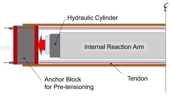
Figure 4.
Force transmission mechanism between internal reaction arm-hydraulic cylinder and strand anchorage.
Figure 4 shows a schematic diagram of the forcing-reaction concept of the anchor block using a hydraulic cylinder and multi-stranded wires. Although this anchor block is analyzed and designed as a compression member, it can show bending behavior when the thickness is thin; therefore, it can be said that it greatly depends on the strength of concrete and the thickness of the steel plate.
Figure 5 shows the internal reaction arm using three PHC (Pre-stressed High-strength Concrete) piles, where the hydraulic cylinder is placed (the middle part of Figure 5), the cross-section of the pre-tensioned U-type girder, the external strand wires, and the single-stranded wires for introducing the pre-tension [12]. An anchoring block for tension is placed in a rectangular position. As long as the width of the girder does not change, this anchor block is designed to be applied to all heights and may be slightly changed according to the cutting method of the strands in the future.
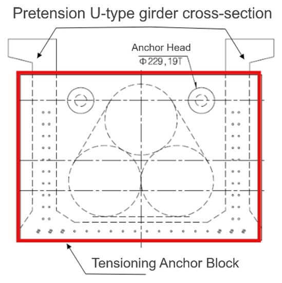
Figure 5.
Cross section of pre-tension U-type girder and anchorage block for tension.
3.1. Consideration for Anchor Block for Pre-Tensioning
It must resist the tension of the external strands for the equilibrium state of the internal reaction arms, along with the rigid composite anchoring block for tension. Therefore, it is necessary to review the following considerations before applying the tension force.
- -
- Anchor blocks that can be moved and transported: A pair must be able to move together as a set, the width and weight are limited for road movement, and the crane capacity is convenient for mounting in the field.
- -
- Anchor block applicable to various mold heights: It can be applied to all mold heights ranging from 1.0 m to 1.7 m and has a convenient width for work.
- -
- Minimum thickness at which deformation does not occur against concentrated loads acting on cylinders and anchorages.
- -
- With the appropriate use of ultra-high-strength concrete (UHPC) considering usability, such as weight and volume, it is expected that the application of UHPC as an anchorage device for compression members greatly depends on the compressive strength of concrete. In the case of UHPC with steel fibers, the tensile strength of approximately 10 MPa is spherical, which is considered to be of great help in the tensile and shear resistance of the anchor block.
3.1.1. Strut-and-Tie Model (STM)
The strut-and-tie model (STM) is a concept used for shear design applied to all parts of a structure, and is a generalization of truss member analysis. The basic concept of a general truss is that the flow of force within the reinforced concrete structure is the same as that within the truss model. In addition, this truss model consists of a compressive stress field (strut) and tension tie connecting the compressive stress field [17,18].
The structural members can be divided into regions B (beams) and D (discontinuous or obstructed). Unlike region B, which is subjected to beam action, the strain in region D acts as an arc and exhibits a non-linear distribution. In addition, the arch action cannot be evaluated in the same way as in Region B because it significantly increases the shear strength. Therefore, the strut-and-tie model suggests a generalized design method for region D in a situation where the evaluation of the design of region D is not performed properly, and it has no choice but to depend on the designer’s experience.
This section examines the compressive stress acting on the member, as shown in Figure 6, using STM for two-dimensional analysis on a plane. This model consists of a left-right symmetrical model, such as a deep beam, and assumes that the lower surface of both ends where the load is applied to the hydraulic cylinder and the mono-strand is fixed, the compression and tensile forces, and the direction (angle) of the strut are calculated.
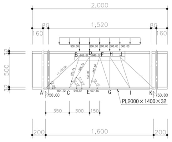
Figure 6.
Strut-and-tie model (STM) of anchor block for pre-tensioning (Unit: mm).
3.1.2. Preliminary Analysis
For a preliminary review of the detailed analysis of a rigid anchor block for tensioning, the commercial program MIDAS [19] was used. Figure 7 shows the numerical model of the anchor block. Each of the three components of the steel plate–concrete–steel plate was modeled as a plate element. In this plate model, the nodes of the three components were connected with rigid-link elements along the load action direction to include each other’s rigidity by restraint. Displacement due to the amount of elongation was allowed.
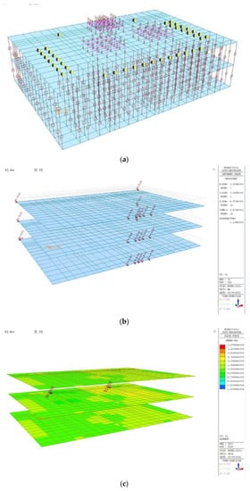

Figure 7.
Plate element model for anchor block and its results. (a) Boundary conditions and node-connections. (b) Displacement results. (c) Shear force results (x-axis). (d) Bending Moment results (x-axis). (e) Bending Moment results (y-axis).
The maximum displacement occurred at the edge of 9 mm, the maximum moment was 2367 kN·m/m (x-axis) and 1168 kN·m/m (y-axis), and a maximum shear force of 14,795 kN/m was generated. It should be noted that the result shown in Figure 8 was used to determine the design of the anchor blocks.
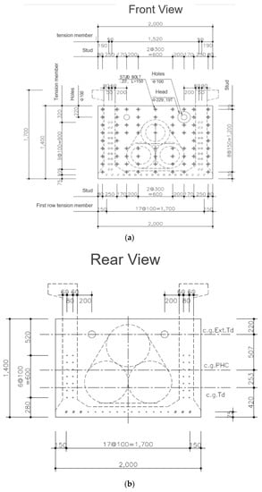
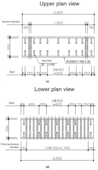
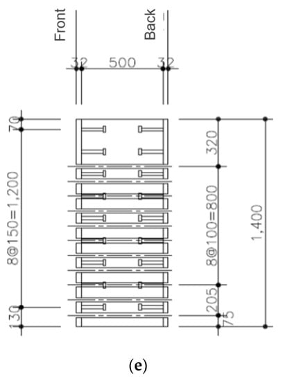
Figure 8.
Detailed drawing of anchor block for pre-tensioning (Unit: mm). (a) Front view of the anchor blocks. (b) Rear view of the anchor blocks. (c) Upper plan view of the anchor blocks. (d) Lower plan view of the anchor blocks. (e) Side view of the anchor blocks.
3.1.3. Final Analysis Model
The design drawings shown in Figure 8 were determined through major considerations and preliminary reviews for the analysis and manufacture of rigid composite anchor blocks for tensioning. Considering the width of the U-type girder, the width of the anchor block was set to 2.0 m, and the height was designed to be 1.4 m. All of the suggested anchor blocks for the cross section of 1.7 m height or less are applicable and can be used for all cross sections of various heights. In addition, UHPC and steel plates (thickness of 32 mm and depth of 0.5 m) were used to reinforce the contact surface on which the load acted. The total weight of this rigid anchor block is 4.9 tonf, that is, 3.5 tonf of UHPCs and 1.4 tonf of steel plates; therefore, it is judged that there will be no difficulty in moving and installing a pair.
3.2. Finite Element Analysis of the Anchor Block
Finite element analysis of the anchor block was performed to examine the behavior of the anchor block when a reaction force was generated by the tension force of the external steel wire and strands when the anchor block was loaded. The external steel wire in the anchor blocks consists of 12 strands and is installed in the upper two locations. In addition, there were 14 single steel wires (mono-strands) on both sides and 12 single wires on the lower sides. The anchor block is a form of sandwiching steel plates on the front and back of the UHPC block. The front, side, and rear views of the fixing block are shown in Figure 8.
3.2.1. FEA Model Using ABAQUS [20]
In this analysis, the front and rear steel plates and the UHPC of the anchor block were modeled as solid elements. The models are shown in Figure 9 and Figure 10.
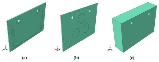
Figure 9.
Anchor block element modeling for (a) front steel part, (b) rear steel part and (c) UHPC part.
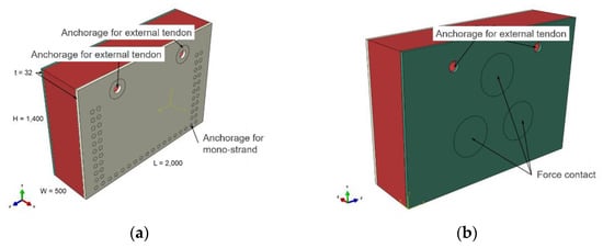
Figure 10.
Anchor block modeling for (a) reaction (front) side and (b) forcing (rear) side.
The external steel wires in the upper two places and 14 single steel wires (mono-strand) in the lower part of both sides were not modeled as material elements but were defined as boundary conditions at the corresponding positions and analyzed so that the reaction force could occur.
3.2.2. Material Properties
For this analysis, the elastic behavior of the steel plate and plastic behavior after yielding were defined, and the physical properties were entered. Table 1 lists the modulus of elasticity, Poisson’s ratio, and unit weight of the steel plate. For the Young’s modulus, a general value of steel is used, and it behaves in a linear elastic manner within the elastic section [12,21]. However, the yield strength of steel was defined as 315 MPa, and the plastic behavior after yielding was entered, as shown in Figure 11.

Table 1.
Material properties for steel plate.
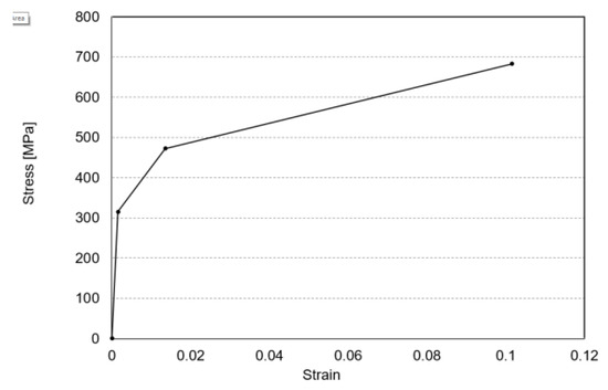
Figure 11.
Stress vs. strain for steel plate.
UHPC applies the Concrete Damaged Plasticity (CDP) model as a material model, which can model various structural materials, including concrete [22,23,24,25]. The concept of isotropic damaged elasticity, including the concept of isotropic tensile and compressive plasticity, can be used to consider the behavior in the elastic region (linear and non-linear behavior) and the behavior after inelastic yielding. Table 2 lists the modulus of elasticity of UHPC, Poisson’s ratio, unit weight, and physical properties of the CDP model [12]. In the CDP model, the behavior after the linear elastic region of concrete is defined in detail, as shown in Figure 12.
Table 2.
Material properties for UHPC (CDP model).
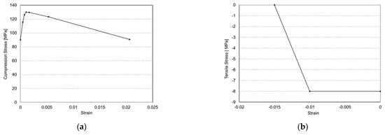
Figure 12.
Behavior after UHPC linear elastic region for (a) compression behavior and (b) tensile behavior).
3.2.3. Contact Properties
The anchor block is a sandwich-type joint of steel plates on the front and rear surfaces of the UHPC block and is mainly compressed by the action of the load and the reaction force. Therefore, in this analysis, it was assumed that the UHPC and the front and rear steel plates behaved integrally and the contact surface was defined as a tie. Figure 13 shows the connection of the tie element between the UHPC and front and rear steel plates.
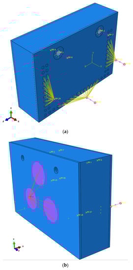
Figure 13.
Spring nodes (coupling) for (a) front side and (b) rear side.
When a load is applied from the rear side, a reaction force is generated from the two upper external steel wires, 14 for each, and the lower 12 single-stranded wires (mono-strands) on both sides of the front part. In this analysis, as described above, the external steel wire and single steel wire are not modeled as material elements, but are connected to a reference node (coupling). A spring coefficient was inputted to the node to apply a reaction force, as shown in Figure 13a. Here, the reaction force parts of the two external steel wires were connected to each reference point, and 14 single steel wires (mono-strands) on both sides were bundled together and connected to each reference point. In addition, 12 single-steel wires (mono-strands) on the lower surface were bundled and connected to the reference point. Similar to the reaction force part, the loading part was modeled such that three loading cylinders were connected with one node (coupling) and loaded simultaneously, as shown in Figure 13b.
3.2.4. Boundary Condition
As described above, in this analysis, the external steel wire anchoring part (two places) of the front reaction force and the single steel wire fixing part (14 places on each side and 12 places on the lower surface) were connected to the reference point (coupling). The boundary condition was defined such that only the reaction force acted by fixing the forward displacement and rotation of the node connected to the mono-strand and the external steel wire anchorage. The Y-direction (U2) and Z-direction (U3) displacements of the fixing block were fixed on the lower boundary surface to prevent rotation under the load. Table 3 presents the boundary conditions for each area.
Table 3.
Boundary condition.
3.2.5. Spring Stiffness
The external steel wire (two places) anchoring part of the front reaction force part and the single steel wire (both sides, bottom) anchoring part were connected to the reference point (coupling), and the reaction force of the external steel wire and the single steel wire were calculated by inputting the spring coefficient. In this case, the spring coefficient of each area was directly inputted by dividing the applied reaction force by the number of single steel wires. Table 4 summarizes the spring coefficients for each reaction-force position [12].
Table 4.
Spring stiffness.
3.2.6. Load Conditions and Mesh
As described above, three cylinders were coupled to one node and modeled such that a load was applied to the node. The applied load in this analysis was 1.5 × 10⁷ N. The fixing block was modeled as a solid structure and a hexahedral mesh was applied. A dense mesh, that is, the maximum distance of the element was 5.0 × 10⁻², was created to increase the precision of the analysis result; the total number of nodes was 38,798 and the total number of elements was 28,832. Figure 14 shows the mesh used in the analysis model.
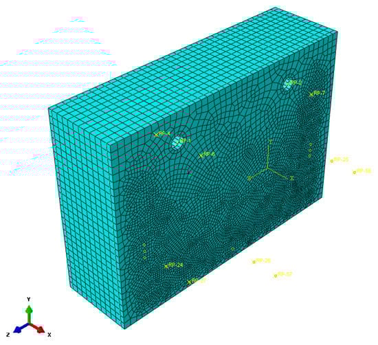
Figure 14.
Mesh of the blocks.
4. FEA Analysis Results of Anchor Block for Tensioning Performance
This anchor block for tensioning is a rigid composite structure, with the front part receiving external force from the hydraulic cylinder and single steel wires (arranged on the web and the lower surface along the U-type section), and the anchor blocks of a bundle of 12 steel wires are placed on the left and right, respectively. It is a steel composite block composed of a 32 mm thick steel plate in the rear part of the block. Ultrahigh-strength concrete (UHPC) with a depth of 50 cm was inserted between the two steel plates to resist compression and shear.
A detailed analysis using ABAQUS was performed to determine the load-bearing capacity and behavior of this structure. Through the behavior of the contact surface between steel and concrete, the analysis of shear and pull-out according to the use of a shear connector (stud) was performed as follows.
The unit of ABAQUS is user defined. Therefore, a consistent unit system should be used for all the input data. The SI (m) unit was used, and all analysis results were derived using the SI unit system.
The analysis revealed that the maximum stress of the steel plate was 215 MPa (compression), which occurred at the top of the external steel wire anchorage above the anchor block; other major deformations and stresses did not occur. The maximum stress generated by UHPC is 92 MPa (compression) (see Figure 15b), which is 71% level for this CDP model fck = 130, considering the material properties of UHPC assumed as linear elasticity up to 0.8 fck (104 MPa). It was confirmed that there were no problems with usability (see Figure 15, Figure 16, Figure 17, Figure 18, Figure 19 and Figure 20). In addition, by examining the equivalent plastic strain (PEEQ), tensile damage (DAMAGET), and scalar stiffness degradation (SDEG), which indicate damage to concrete, it was confirmed that no damage (crack) occurred in the UHPC member.
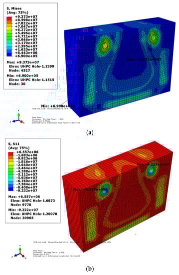
Figure 15.
Stress of concrete in reaction (front) side for (a) von Mises stress and (b) stress on the x face in the x direction.
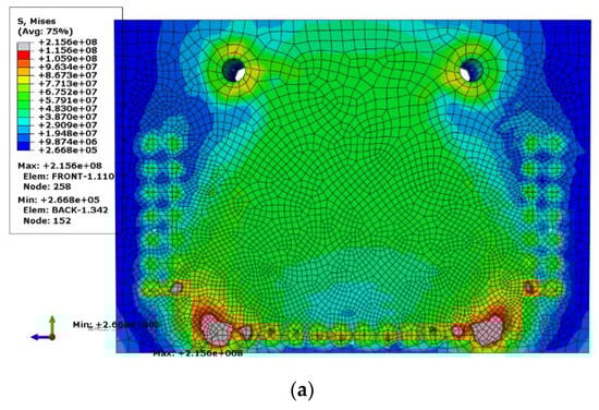
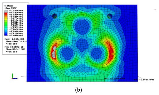
Figure 16.
Stress components and invariants for (a) reaction (front) side and (b) forcing (rear) side.
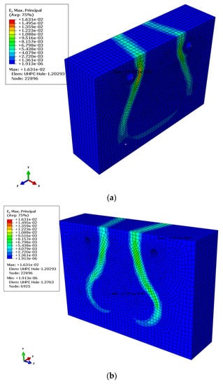
Figure 17.
Total strain components, Max, Principal Strain for (a) reaction (front) side and (b) forcing (rear) side.
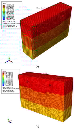
Figure 18.
Concrete + steel displacements (U, U1) for (a) reaction (front) side and (b) forcing (rear) side.
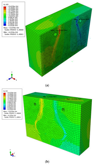
Figure 19.
Concrete + steel displacements (U, U3) for (a) reaction (front) side and (b) forcing (rear) side.
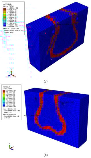
Figure 20.
Actively yielding concrete failure/fracture for (a) reaction (front) side and (b) forcing (rear) side.
5. Conclusions
In this study, a pre-tension method using a hydraulic cylinder that can be manufactured on-site and is easy to move for repeated production, and a concrete pile used as an internal reaction force was proposed. The results of the finite element analysis performed to verify the performance of the steel-UHPC anchor block led to the following conclusions:
- To simulate the reaction force of the steel wire anchorage according to the loading of the hydraulic cylinder, a reaction-force-type model was constructed that allowed a certain displacement by using a spring in the anchorage of the entire mono anchorage and the upper external steel wire. A maximum parallel movement of 89 mm was made in the direction of load application, and the upper surface of the fixing block moved 7.4 mm more than the lower surface, showing a slightly inclined displacement. This is considered to be a rotation caused by not matching the centroids of the three hydraulic cylinders and the centroids of the reaction forces.
- There was no bending deformation along the shear plane on the plane, but there was a slight difference in the displacement between both sides and the center in the section where the central load was applied. This shows a small value owing to the displacement according to the overall movement, but a larger value may be shown if the entire movement without tilting deformation is the same. Therefore, a re-examination with a changed load position is required.
- As described above, the contact surface of steel to concrete does not exhibit shear behavior (shear resistance at the joint surface) owing to slip; therefore, the shear force acting on the shear connection material can be neglected. However, it is better to arrange the shear connecting material evenly on the front joint surface at regular intervals for synthesis.
- The maximum stress of the steel plate was 215 MPa (compression), which occurred at the top of the outer steel wire anchorage of the fixing block; no other major deformations or stresses occurred.
- The maximum stress generated by UHPC is 92 MPa (compression), which is a problem in usability considering the material properties of UHPC assumed as linear elasticity up to 0.8 fck (104 MPa) at 71% level for this CDP model fck = 130. It is determined that there is no problem in pretension because damage (cracking) of the UHPC does not occur, and it is possible to reuse it.
Author Contributions
Conceptualization, D.-W.S.; Formal analysis, D.-W.S. and S.P.; Funding acquisition, K.-T.P.; Investigation, S.P. and Y.-W.S.; Project administration, K.-T.P.; Validation, H.-O.J. and Y.-W.S.; Writing—original draft, D.-W.S. and S.P.; Writing—review & editing, H.-O.J. and Y.-W.S. All authors have read and agreed to the published version of the manuscript.
Funding
This study was supported by the Ministry of Science and ICT (MSIT) grant by the Korea Institute of Civil Engineering and Building Technology (KICT). (Project Number: KICT-20220102-001).
Institutional Review Board Statement
Not applicable.
Informed Consent Statement
Not applicable.
Data Availability Statement
Not applicable.
Conflicts of Interest
The authors declare no conflict of interest.
References
- MOLIT. Road Bridge and Tunnel Status Report; MOLIT: Sejong City, Republic of Korea, 2022. [Google Scholar]
- MOLIT. Budget Status of Land, Infrastructure and Transport Report; MOLIT: Sejong City, Republic of Korea, 2022. [Google Scholar]
- Shin, H.S. PSC Beam Fall Prevention Method. Road Transp. 2005, 99, 93–107. [Google Scholar]
- Koo, M.-S.; Kim, H.-H.; Jung, Y.-D. A Study of Continuous PSC Bridge with a Reinforcement Steel Plate. In Proceedings of the Computational Structural Engineering Institute of Korea 2005 Annual Conference (Spring), Seoul, Republic of Korea, April 2005; pp. 422–429. [Google Scholar]
- Kim, J.H.; Park, K.H.; Joo, B.C.; Lee, S.Y.; Jin, H.J.; Ko, S.G.; Kang, S.H.; Kim, D.Y. Development of Improved PSC Girder Bridge with Precast Core; Korea Institute of Civil Engineering and Building Technology: Seoul, Republic of Korea, 2017; pp. 1–39. [Google Scholar]
- Kim, K.-S.; Yang, I.-H. PSC Development of New Type PSC Beam Girder Bridges in Korea. Mag. Korea Concr. Inst. 2008, 20, 26–33. [Google Scholar]
- Bae, K.-M.; Min, K.-H.; Lee, C.-O.; Lim, N.-H. Analysis and Improvement of Long-term Deflection of PSC I Girder for Railway Bridges. Korean Soc. Hazard Mitig. 2017, 17, 9–15. [Google Scholar] [CrossRef]
- Bridge Technology Inc. Development and Commercialization of Slab Integrated Low Height PSC-I Girder Upper Bridge System using Long Span Arch-Deck Panel; Bridge Technology Inc.: Seoul, Republic of Korea, 2018. [Google Scholar]
- Guo, L.; Liu, Y.; Qu, B. Fully composite beams with U-shaped steel girders: Full-scale tests, computer simulations, and simplified analysis models. Eng. Struct. 2018, 177, 724–738. [Google Scholar] [CrossRef]
- Svoboda, A.; Klusáček, L.; Olšák, M. Strengthening and Rehabilitation of U-Shaped RC Bridges Using Substitute Cable Ducts. Adv. Mater. Sci. Eng. 2019, 2019, 8920718. [Google Scholar] [CrossRef]
- Zhang, J.; Jing, Y.; Li, P.; Han, W.; Zhang, N.; Zhou, Y. Experimental and numerical investigation on the ultimate vertical bearing capacity of U-shaped girder with damaged web. Sensors 2019, 19, 3735. [Google Scholar] [CrossRef] [PubMed]
- Seo, D.-W.; Kang, S.H.; Kim, S.T.; Kim, J.H.; Kim, H.S.; Park, K.-T.; Park, S.; Park, H.S.; Song, J.J.; Yooj, W.K.; et al. Development of High-efficiency Road Bridge Technology Customized for New Southern Countries and Establishment of Local Commercialization; Korea Institute of Civil Engineering and Building Technology: Seoul, Republic of Korea, 2021. [Google Scholar]
- Hewson, N.R. Prestressed Concrete Bridges: Design and Construction; Thomas Telford Publishing: London, UK, 2003. [Google Scholar]
- Bažant, Z.P.; Yu, Q.; Li, G.-H. Excessive Long-Time Deflections of Prestressed Box Girders. I: Record-Span Bridge in Palau and Other Paradigms. J. Struct. Eng. 2012, 138, 676–686. [Google Scholar] [CrossRef]
- Xie, J.; Wang, G.-L.; Zheng, X.-H. Review of Study of Long-term Deflection for Long Span Prestressed Concrete Box-girder Bridge. J. Highw. Transp. Res. Dev. 2007, 2, 47. [Google Scholar] [CrossRef]
- Collins, M.P.; Mitchell, D. Prestressed Concrete Structures; Prentice Hall: Hoboken, NJ, USA, 1991. [Google Scholar]
- Wight, J.K.; Parra-Montesinos, G. Strut and Tie Model for Deep Beam Design. Concr. Int. 2003, 25, 63–70. [Google Scholar]
- ACI Committee 318; American Concrete Institute; International Organization for Standardization. Building Code Requirements for Structural Concrete (ACI 318M-08) and Commentary; American Concrete Institute: Farmington Hills, MI, USA, 2008; ISBN 9780870312830. [Google Scholar]
- MIDAS IT. MIDAS Civil 2021 Analysis Reference; MIDAS Information Technology Co., Ltd.: Seoul, Republic of Korea, 2021. [Google Scholar]
- Dassault System ABAQUS User’s Manual 2021; Dassault Systèmes Simulia Corp.: Framingham, MA, USA, 2021.
- Elnashai, A.S.; Izzuddin, B.A. Modelling of material non-linearities in steel structures subjected to transient dynamic loading. Earthq. Eng. Struct. Dyn. 1993, 22, 509–532. [Google Scholar] [CrossRef]
- Grassl, P.; Lundgren, K.; Gylltoft, K. Concrete in Compression: A Plasticity Theory with a Novel Hardening Law. Int. J. Solids Struct. 2002, 39, 5205–5223. [Google Scholar] [CrossRef]
- Grassl, P.; Jirásek, M. Damage-plastic model for concrete failure. Int. J. Solids Struct. 2006, 43, 7166–7196. [Google Scholar] [CrossRef]
- Grassl, P.; Jirásek, M. Plastic model with non-local damage applied to concrete. Int. J. Numer. Anal. Methods Geomech. 2006, 30, 71–90. [Google Scholar] [CrossRef]
- Hafezolghorani, M.; Hejazi, F.; Vaghei, R.; Jaafar, M.S.B.; Karimzade, K. Simplified Damage Plasticity Model for Concrete. Struct. Eng. Int. 2017, 27, 68–78. [Google Scholar] [CrossRef]


Publisher’s Note: MDPI stays neutral with regard to jurisdictional claims in published maps and institutional affiliations. |
© 2022 by the authors. Licensee MDPI, Basel, Switzerland. This article is an open access article distributed under the terms and conditions of the Creative Commons Attribution (CC BY) license (https://creativecommons.org/licenses/by/4.0/).