
Development of Digital Device Using ZigBee for Environmental Monitoring in Underground Mines

Abstract
:1. Introduction
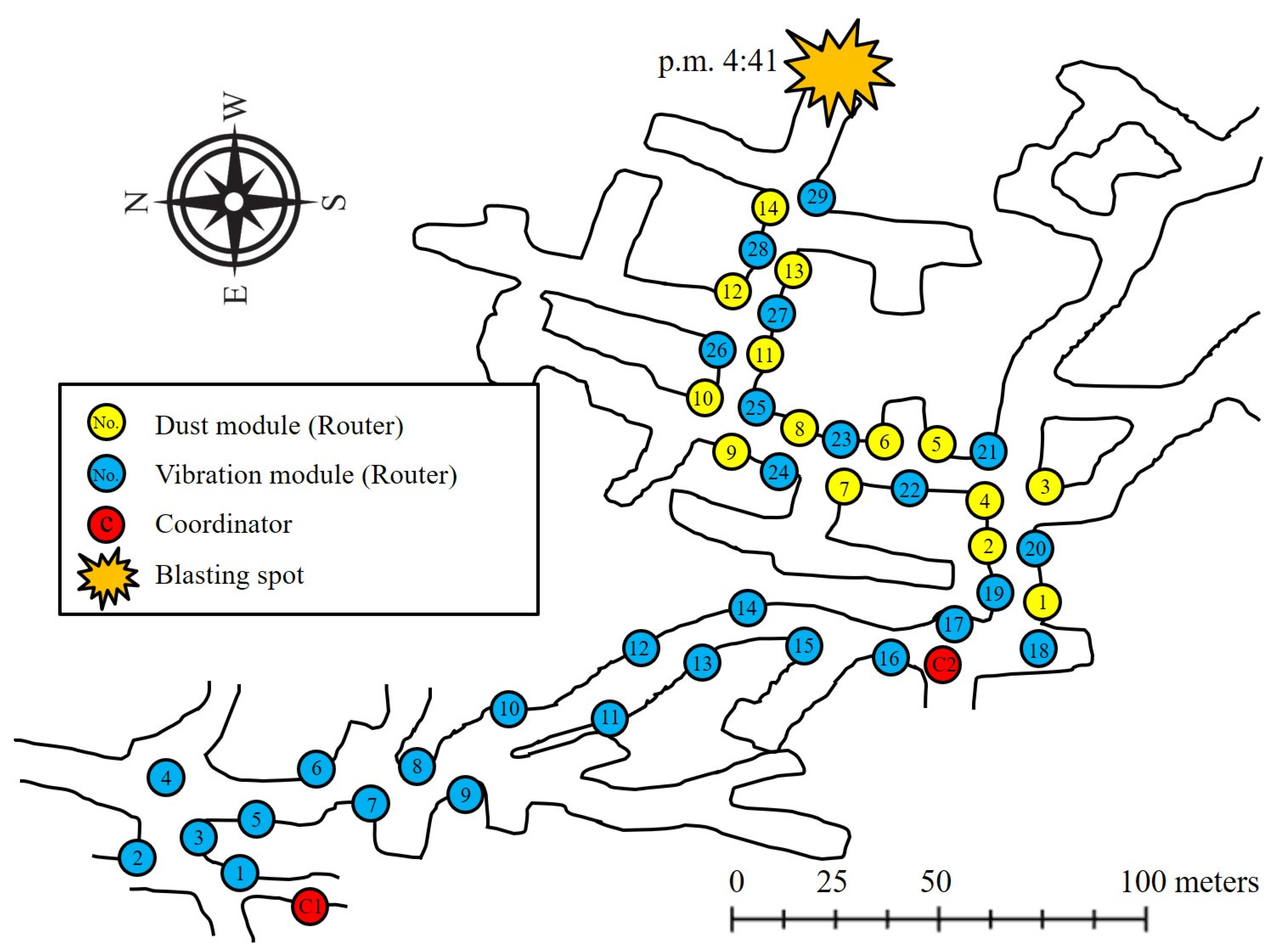
2. Study Area
3. Methods
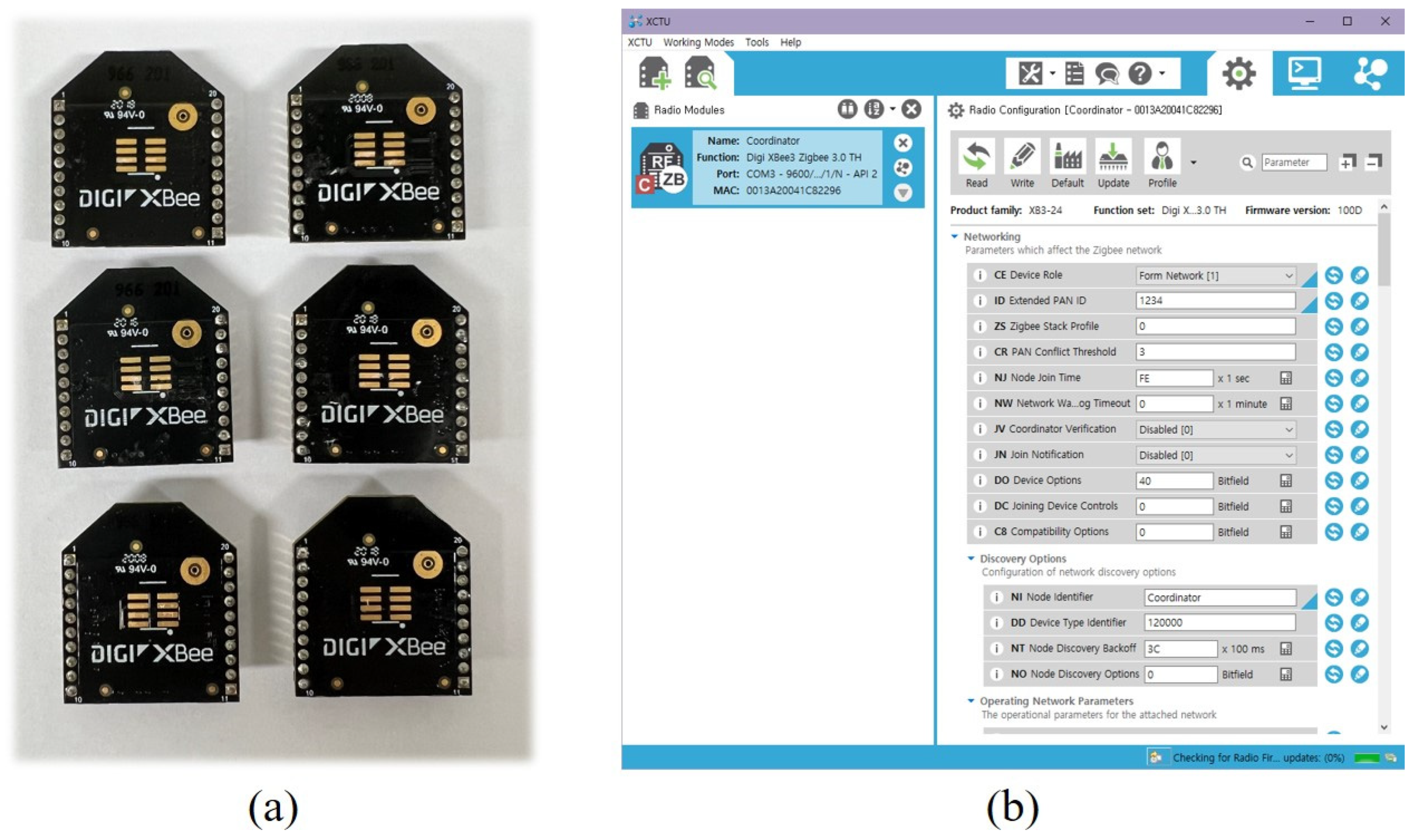
3.1. ZigBee Module for Communication
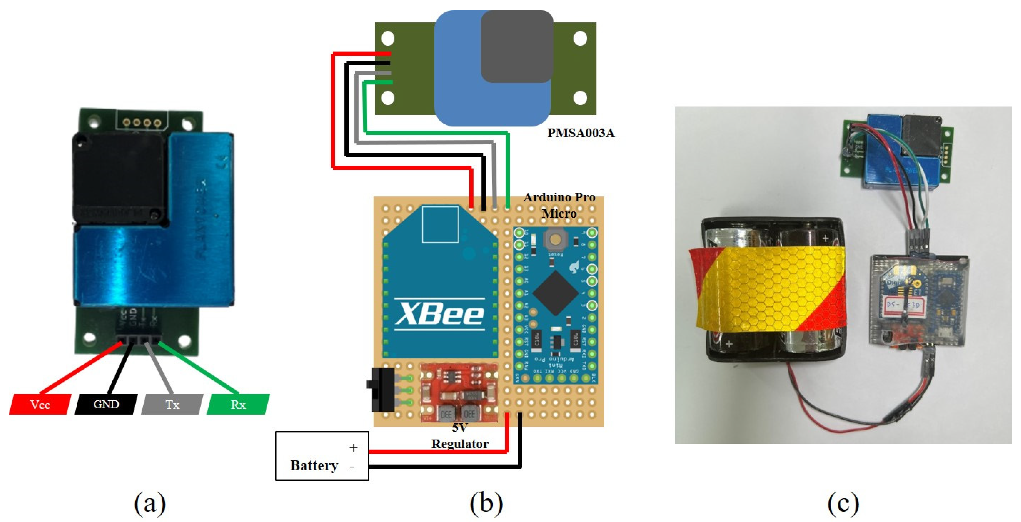
3.2. Development of Vibration Measurement Module
3.3. Development of Dust Measurement Module
3.4. Module Installation and Data Acquisition in Underground Mine
4. Results
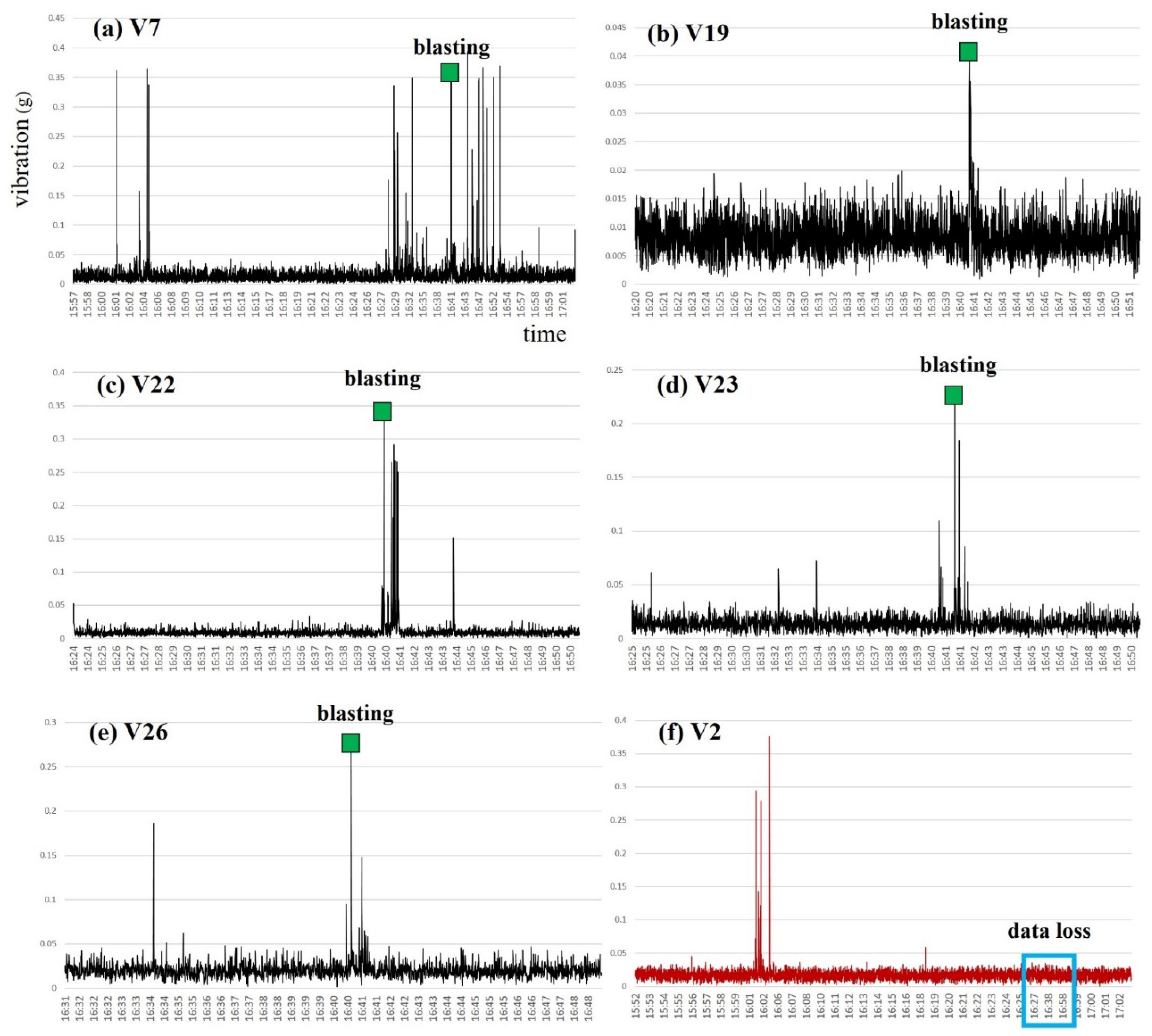
4.1. Vibration Measurement Result
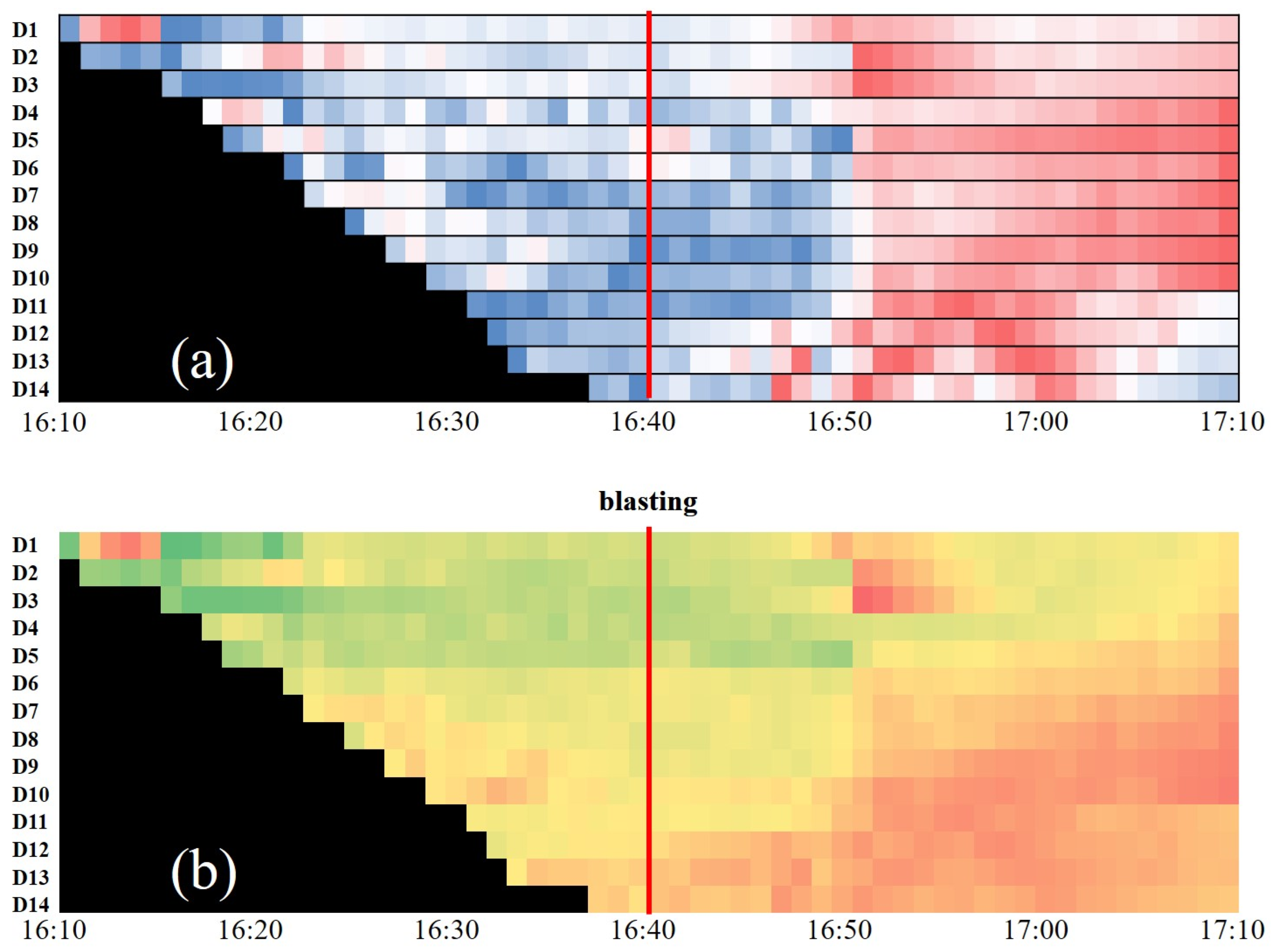
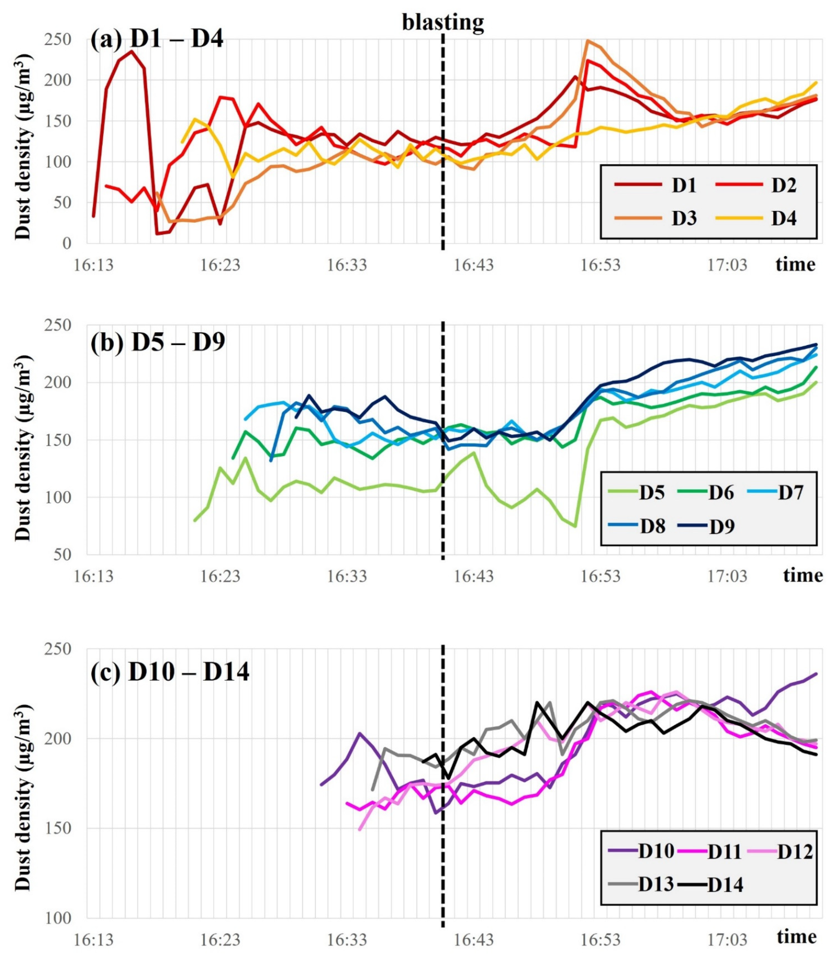
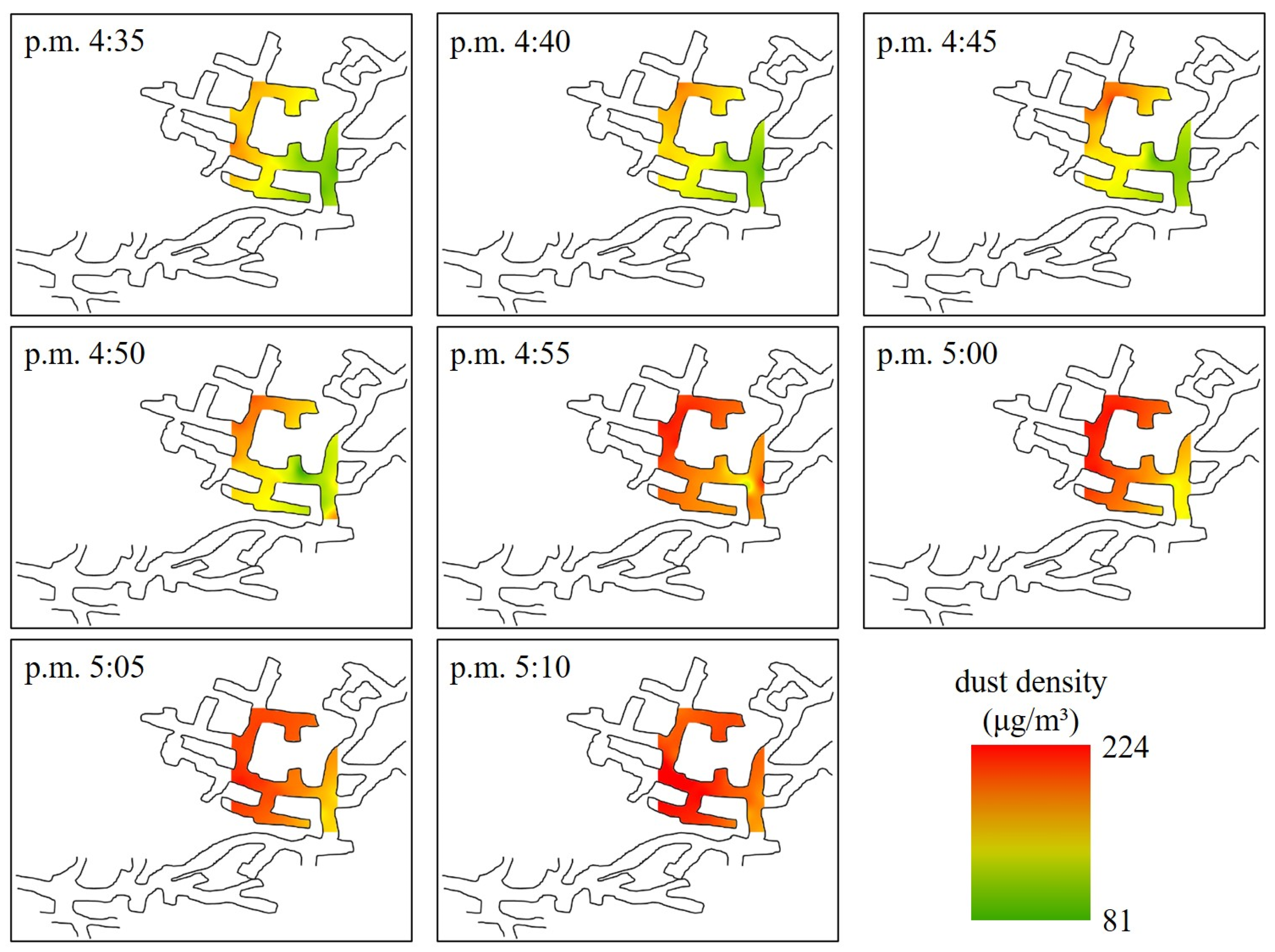
4.2. Dust Measurement Result
5. Discussion
- (1)
- The vibration measurement module was set as an end device to minimize power consumption in the preliminary experiment. Unlike a router, which can send and receive data, the end device can only transmit the acquired data. Therefore, the number of routers was small compared to that of the end device; hence, the network connection was easily disconnected, and data acquisition was unstable in some vibration measurement modules. To address this, in this study, the number of router modules was increased by setting the vibration measurement module as a router, and the communication stability was improved.
- (2)
- In the preliminary experiment, by setting the vibration measurement module as an end device and applying the sleep mode, the battery life was increased, compared to supplying power at all times. However, when the power was turned off and on during the sleep mode, the connection to the WSN was weaker than when the power was constantly supplied. The stability of the network is generally low in underground mines compared to laboratories. Because the underground power supply is a crucial issue, if a permanent power supply is impossible, it is necessary to consider a method of reducing battery consumption in sleep mode. However, for this, it is a prerequisite to maintain a stable network through the optimal arrangement of modules.
- (3)
- The sensors were arranged as linear or branched, considering the shape of a long mine shaft. Although the arrangement of the sensors appears to be a simple linear arrangement, in reality, multiple sensors can be directly connected to each other because the distance between adjacent modules was approximately 30–50 m. However, it is not possible to form a complex network. Increasing the number of router modules can be a solution to configure a more stable network. Thus, the stability of the network can be maintained even if the intermediate node does not function properly; however, this means that the required capital increases. Moreover, if continuous power supply through wires is difficult, it increases the number of devices to be replaced with batteries. Therefore, we must determine the optimal module arrangement by simultaneously considering the stability of the network, budget, and power supply possibility.
- (4)
- Owing to the nature of ZigBee, only one coordinator module can exist in a network, and the data transmitted from each node is concentrated in the coordinator module. Therefore, because there are many sensor modules in one network, the data load increases and may exceed the limit that can be processed by the coordinator. To solve this problem, there is a method for configuring multiple networks by increasing the number of coordinators, and the data load can be reduced by adjusting the sampling rate. Increasing the number of coordinators can be an effective method, but it requires multiple storage devices to be installed underground. Adjusting the sampling rate is useful when acquiring data at short intervals is unnecessary; however, in the opposite case, it is less useful. Therefore, we must select the optimal number of coordinators and sampling rate according to the purpose of monitoring and the environment of the underground mine.
- (5)
- Regardless of how well the network is configured, communication cannot be fully performed if the power of each device is insufficient. The XBee module operates at a voltage of 3.3V, but the required power increases when a microcontroller, such as an Arduino or other sensors, is connected. Therefore, we must determine whether the battery system supplies sufficient power for communication. In the preliminary experiment, the XBee S2C product was used, but in this study, it was replaced with the XBee 3 Pro product to improve communication performance.
- (6)
- Although electromagnetic waves can be partially transmitted over obstacles, owing to diffraction and reflection, they are emitted along a straight path. Therefore, it is important to secure LOS between devices for smooth communication. Because the underground mine is surrounded by solid rock walls, the LOS must be secured such that there are no obstacles between the modules. However, it was difficult to fully consider the communication range and LOS of the module because the installation work was conducted depending on the paper map and intuition of the installer in a dark and inconvenient environment. Therefore, if 3D modeling and LOS analysis of underground tunnels are performed in advance, a more effective network can be built.
6. Conclusions
Author Contributions
Funding
Conflicts of Interest
Abbreviations and Symbols
| DPM | diesel particulate matter |
| GPRS | general packet radio service |
| GSM | global system for mobile communications |
| IoT | Internet of Things |
| LiDAR | light detection and ranging |
| LOS | line of sight |
| MEMS | micro-electromechanical system |
| NFC | near-field communication |
| RF | radio frequency |
| WSN | wireless sensor network |
References
- Roy, M.P.; Singh, P.K.; Sarim, M.; Shekhawat, L.S. Blast design and vibration control at an underground metal mine for the safety of surface structures. Int. J. Rock Mech. Min. Sci. 2016, 83, 107–115. [Google Scholar] [CrossRef]
- He, J.; Dou, L.; Gong, S.; Li, J.; Ma, Z.Q. Rock burst assessment and prediction by dynamic and static stress analysis based on micro-seismic monitoring. Int. J. Rock Mech. Min. Sci. 2017, 93, 46–53. [Google Scholar] [CrossRef]
- Hu, S.; Tan, Y.; Ning, J.; Guo, W.Y.; Liu, X. Multiparameter Monitoring and Prevention of Fault-Slip Rock Burst. Shock Vib. 2017, 2017, 1–8. [Google Scholar] [CrossRef] [Green Version]
- Yang, C.; Luo, Z.; Hu, G.; Liu, X. Application of a microseismic monitoring system in deep mining. J. Univ. Sci. Technol. Beijing Miner. Metall. Mater. 2007, 14, 6–8. [Google Scholar] [CrossRef]
- Huang, Y.; Bao, M.; Xiao, J.; Qiu, Z.; Wu, K. Effects of PM2.5 on Cardio-Pulmonary Function Injury in Open Manganese Mine Workers. Int. J. Environ. Res. Public Health 2019, 16, 2017. [Google Scholar] [CrossRef] [PubMed] [Green Version]
- Brodny, J.; Tutak, M. Exposure to Harmful Dusts on Fully Powered Longwall Coal Mines in Poland. Int. J. Environ. Res. Public Health 2018, 15, 1846. [Google Scholar] [CrossRef] [PubMed] [Green Version]
- Bugarski, A.D.; Schnakenberg, G.H., Jr.; Hummer, J.A.; Cauda, E.; Janisko, S.J.; Patts, L.D. Effects of Diesel Exhaust Aftertreatment Devices on Concentrations and Size Distribution of Aerosols in Underground Mine Air. Environ. Sci. Technol. 2009, 43, 6737–6743. [Google Scholar] [CrossRef] [PubMed]
- Lee, S.; Park, Y.; Lee, H.; Kim, J. Review of Environmental Monitoring and Communication System in Underground Mines Using Wireless Sensor Network. Tunn. Undergr. Space 2018, 28, 209–231. [Google Scholar]
- Sun, E.; Zhang, X.; Li, Z. The internet of things (IOT) and cloud computing (CC) based tailings dam monitoring and pre-alarm system in mines. Saf. Sci. 2021, 50, 811–815. [Google Scholar] [CrossRef]
- Prashanth, R.; Nimaje, D.S. Development of blast-induced ground vibration wireless monitoring system. In Proceedings of the 39th Application of Computers and Operations Research in the Mineral Industry (APCOM 2019), Wroclaw, Poland, 30 May 2019; pp. 595–602. [Google Scholar]
- Gangwar, K.; Chen, G.C.Y.; Chan, K.K.M.; Gangwar, R.K.; Rambabu, K. Antenna System for Communication in Underground Mining Environment to Ensure Miners Safety. IEEE Access 2021, 9, 150162–150171. [Google Scholar] [CrossRef]
- Ziętek, B.; Banasiewicz, A.; Zimroz, R.; Szrek, J.; Gola, S. A Portable Environmental Data-Monitoring System for Air Hazard Evaluation in Deep Underground Mines. Energies 2020, 13, 6331. [Google Scholar] [CrossRef]
- Singh, N.; Gunjan, V.K.; Chaudhary, G.; Kaluri, R.; Victor, N.; Lakshmanna, K. IoT enabled HELMET to safeguard the health of mine workers. Comput. Commun. 2022, 193, 1–9. [Google Scholar] [CrossRef]
- Jo, B.; Khan, R.M.A. An Internet of Things System for Underground Mine Air Quality Pollutant Prediction Based on Azure Machine Learning. Sensors 2018, 18, 930. [Google Scholar] [CrossRef] [PubMed] [Green Version]
- Dey, P.; Chaulya, S.K.; Kumar, S. Hybrid CNN-LSTM and IoT-based coal mine hazards monitoring and prediction system. Process Saf. Environ. Prot. 2021, 152, 249–263. [Google Scholar] [CrossRef]
- Duarte, J.; Rodrigues, F.; Castelo Branco, J. Sensing Technology Applications in the Mining Industry—A Systematic Review. Int. J. Environ. Res. Public Health 2022, 19, 2334. [Google Scholar] [CrossRef] [PubMed]
- Wang, L.; Wang, Z.; He, Z.; Gao, X. Research of physical condition monitoring system for the elderly based on Zigbee wireless network technology. In Proceedings of the International Conference on E-Health Networking Digital Ecosystems and Technologies (EDT), Shenzhen, China, 17–18 April 2010; pp. 32–35. [Google Scholar] [CrossRef]
- Nasirudin, M.A.; Za’bah, U.N.; Sidek, O. Fresh water real-time monitoring system based on Wireless Sensor Network and GSM. In Proceedings of the 2011 IEEE Conference on Open Systems, Langkawi, Malaysia, 25–28 September 2011; pp. 354–357. [Google Scholar]
- Sadeghi, S.; Soltanmohammadlou, N.; Nasirzadeh, F. Applications of Wireless Sensor Networks to Improve Occupational Safety and Health in Underground Mines. J. Safety Res. 2022, in press. [CrossRef]
- Sudha, M.S.; Kumar, K.; Madhukesh, N.M.; Baig, N.; Naveen, T. Coal Mine Safety System Using Wireless Sensor Network. Int. J. Res. Eng 2020, 3, 737–740. [Google Scholar]
- Duan, W.; Chen, G. Innovation and Application of an Automatic Control System for Gas Wells Production in Sulige Gas Field. J. Phys. Conf. Ser. 2018, 1074, 012123. [Google Scholar] [CrossRef]
- Noh, J.H.; Oh, S.J. Hydrothermal Alteration of the Pungchon Limestone and the Formation of High-Ca Limestone. J. Geol. Soc. Korea 2005, 41, 175–197. [Google Scholar]
- Chen, S.K.; Kao, T.; Chan, C.T.; Huang, C.N.; Chiang, C.Y.; Lai, C.Y.; Tung, T.H.; Wang, P.C. A Reliable Transmission Protocol for ZigBee-Based Wireless Patient Monitoring. IEEE Trans. Inf. Technol. Biomed. 2011, 16, 6–16. [Google Scholar] [CrossRef] [PubMed]
- Siekkinen, M.; Hiienkari, M.; Nurminen, J.K.; Nieminen, J. How low energy is bluetooth low energy? Comparative measurements with ZigBee/802.15.4. In Proceedings of the 2012 IEEE Wireless Communications and Networking Conference Workshops (WCNCW), Paris, France, 1 April 2012; pp. 232–237. [Google Scholar]


| Wireless Technical Standards | ZigBee/802.15.4 | Bluetooth | Wi-Fi | GSM 1/GPRS 2 |
|---|---|---|---|---|
| System resource requirements | 4 KB–32 KB | >250 KB | >1 MB | >16 MB |
| Power waste | Low | Common | Common | High |
| Battery life (days) | 100–1000+ | 1–7 | 1–5 | 1–7 |
| Number of nodes in local network | 65,000+ | 7 | 30 | 1000+ |
| Data rate (Kbps) | 20–250 | 1000 | 11,000+ | 64–128 |
| Communication distance | 1–3200 | 1–10+ | 1–100 | 1000+ |
| Advantage | Reliability, low cost, low power consumption | Low cost and easy to operate | High speed and adaptability | Good transmission quality and large coverage range |
| Applications | Wireless detection and control | Short-distance data transmission | A lot of data transmissions such as Web access and video. | Voice and data transmission |
Publisher’s Note: MDPI stays neutral with regard to jurisdictional claims in published maps and institutional affiliations. |
© 2022 by the authors. Licensee MDPI, Basel, Switzerland. This article is an open access article distributed under the terms and conditions of the Creative Commons Attribution (CC BY) license (https://creativecommons.org/licenses/by/4.0/).
Share and Cite
Lee, W.-H.; Kim, H.; Lee, C.-H.; Kim, S.-M. Development of Digital Device Using ZigBee for Environmental Monitoring in Underground Mines. Appl. Sci. 2022, 12, 11927. https://doi.org/10.3390/app122311927
Lee W-H, Kim H, Lee C-H, Kim S-M. Development of Digital Device Using ZigBee for Environmental Monitoring in Underground Mines. Applied Sciences. 2022; 12(23):11927. https://doi.org/10.3390/app122311927
Chicago/Turabian StyleLee, Woo-Hyuk, Hojin Kim, Chung-Hyun Lee, and Sung-Min Kim. 2022. "Development of Digital Device Using ZigBee for Environmental Monitoring in Underground Mines" Applied Sciences 12, no. 23: 11927. https://doi.org/10.3390/app122311927