Abstract
To address the problem of structural performance degradation caused by hinged joints and pavement damage, we utilized actual engineering to conduct a construction study on the overall replacement of pavement and hinge joint reinforcement in ultra-high-performance concrete (UHPC) hollow slab girder bridges. A replacement and reinforcement design was developed and reconstruction was undertaken. By using UHPC and reinforcement bars, the adjacent slab girders were designed to work together under specific construction process guarantees for the characteristics of UHPC. The corresponding interface treatment and a combination of planting bars and steel mesh were necessary. According to the strain and deflection monitoring results, the overall performance of the bridge after pavement and hinge joint reinforcement was verified. The strain amplitude of the reinforcement was approximately 10 με, and that of the concrete was approximately 5 με. The deflection difference of the adjacent girder was similar, which proved that the hinge joints connect girders and transfer force effectively. All the results clearly demonstrated the positive overall effect of the UHPC replacement method. The conclusions could provide a reference for the reinforcement and reconstruction of similar projects.
1. Introduction
Prestressed concrete bridges account for more than 90% of the total number of bridges in China. Precast hollow slab girder bridges have been widely used in road bridges with medium and short spans due to their simple structure, convenient construction, and high degree of industrialization [1]. It is a very common bridge form used in medium- and short-span bridges around the world. Taking Zhejiang Province as an example, medium- and small-span bridges account for more than 90% of the total number of bridges, of which hollow slab girder bridges account for the absolute majority [2].
Given the service time required, increasing traffic flow and overloading, a large number of hollow slab girder bridges have deteriorated significantly. In early-built hollow slab girder bridges, due to the unsuitable hinge joint structure, the single slab girder loading state occurs after the hinge joint has been damaged, which affects the safety of the bridge [2,3,4,5]. Compared with other types of structural cracking, damage in the pavement layer or in the structural layer of the bridge runs from the point of damage to the surface, which eventually causes damage to the structure. The existing technical method for the treatment of bridge deck defects usually involves the removal of the pavement and the structural layer as a whole and repaving them [6,7]. In this process, due to the time required for multiple processes such as cutting, paving, and maintenance, the construction period is long, which has a substantial social and economic impact.
Ultra-high-performance concrete (UHPC) has excellent properties, such as toughness, high compressive strength and good durability. The UHPC–NC (normal concrete) composite structure is an important area of research in regard to UHPC application as it provides new options for the reinforcement of ordinary reinforced concrete (RC) structures, especially in harsh environments such as coastal, petroleum, chemical, saline–alkali, and deicing salt, as well as in conditions of fatigue or impact. UHPC is used to cover the existing service structure as it is not only waterproof, but it also reinforces and is especially suitable for bridge deck pavement and structural reinforcement [8,9,10]. The use of UHPC to ensure good ductility in bridge deck pavements has achieved good results and has been applied in many projects, which proves that the implementation of UHPC is fully integrated with the base structure. Improvements in structural performance have been achieved, even in thinner pavement.
Bruhwiler and his collaborators have performed many basic studies using UHPC to reinforce ordinary RC structures, especially for bridge deck pavement [11,12,13,14]. This application has achieved good results. The team also authored the Swiss UHPC standard, which contains relevant chapters on how to use UHPC to reinforce RC structures, including important details such as the requirements for the design and construction of different UHPC–RC combinations. These also involve the UHPC’s performance, the interactions between the UHPC and the existing structure, the reinforcement and protection functions of the structure, and the tensile, compressive, and fatigue resistance of the UHPC-RC structure in the process. An important conclusion is that when UHPC is used for bridge deck reinforcement, it is necessary to solve the problem of interface bonding at the UHPC-RC interface [15,16].
Treating the surface of the existing RC structure is necessary to ensure the performance of the bond between the UHPC and the RC bridge. This includes removing, grinding or grooving, cleaning the damaged part/s (partial or overall), laying the rebar mesh (or not laying), pouring the UHPC, and the final surface treatment (grinding or grooving, or covering) after curing to the specified age [7,11,12]. The thickness of the laid UHPC is usually approximately 50 mm to 100 mm, while he thickness of the common cover or pavement is usually between 25 and 50 mm. When stiffness, fatigue resistance, and wear resistance need to be considered, the thickness of the UHPC can be appropriately increased [17]. According to the process outlined above, the construction process takes a long time, and the construction period and its impact are significant. Therefore, an ideal reinforcement scheme includes a small amount of rebar operation and rebar planting to increase the interaction between the UHPC and the RC structure, or even the direct paving of the UHPC [18,19].
In this paper, based on actual engineering applications, combined with domestic and foreign research [20], the structural performance of UHPC direct paving to replace the pavement of a hollow slab girder bridge was investigated. The advantages of UHPC in the reinforcement of a bridge deck structure are expected to be fully utilized, and the disadvantages related to the complex processes and long construction periods associated with the existing reinforcement are expected to be avoided.
2. Background Engineering
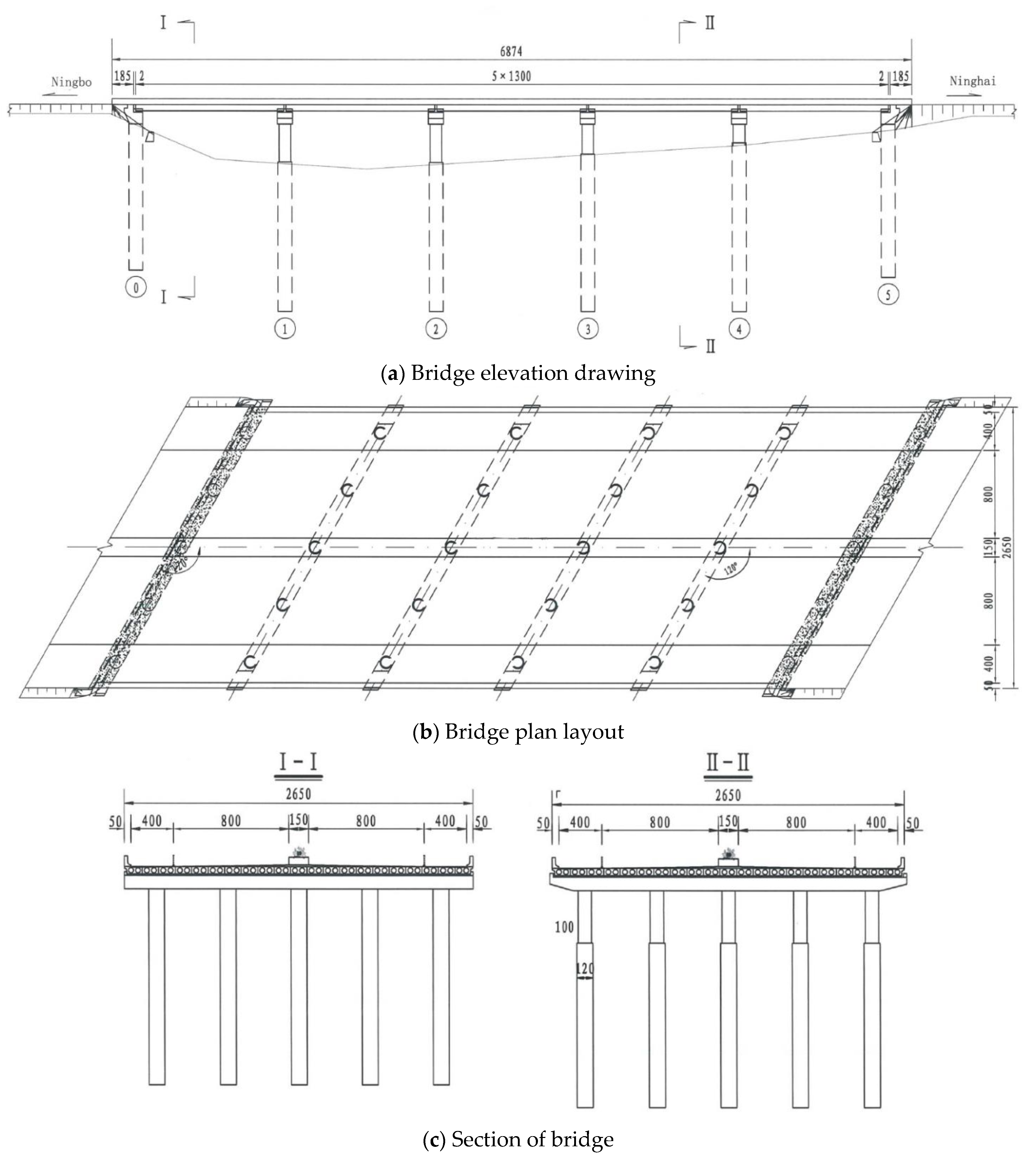
The Zhuxing Bridge is located on the S214 Yonglin line in Ninghai County, Zhejiang Province. It was completed and opened in 1997 (Figure 1). The current bridge deck pavement consists of 10 cm thick concrete pavement.
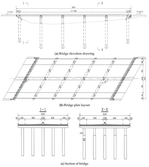
Figure 1.
The bridge layout (unit: cm).
The bridge was tested by the Ningbo Traffic Construction Engineering Test and Inspection Center Co., Ltd. in 2020. The overall technical condition of the bridge was assessed as Class 2. The main defects were pavement damage, local damage to the expansion joints, and local damage to the anti-collision walls. Part of the concrete surface of the slab girder was stripped and exposed, with multiple cracks, and the bridge deck pavement was worn and exposed with cracks. In the “Construction Drawing Design of Zhuxing Bridge Maintenance and Reinforcement Project of G228 Dandong Line in Ninghai County” published by the Ningbo Transportation Planning and Design Institute Co., Ltd. in April 2020, the slab and pier column defects were reinforced with CFRP plates.
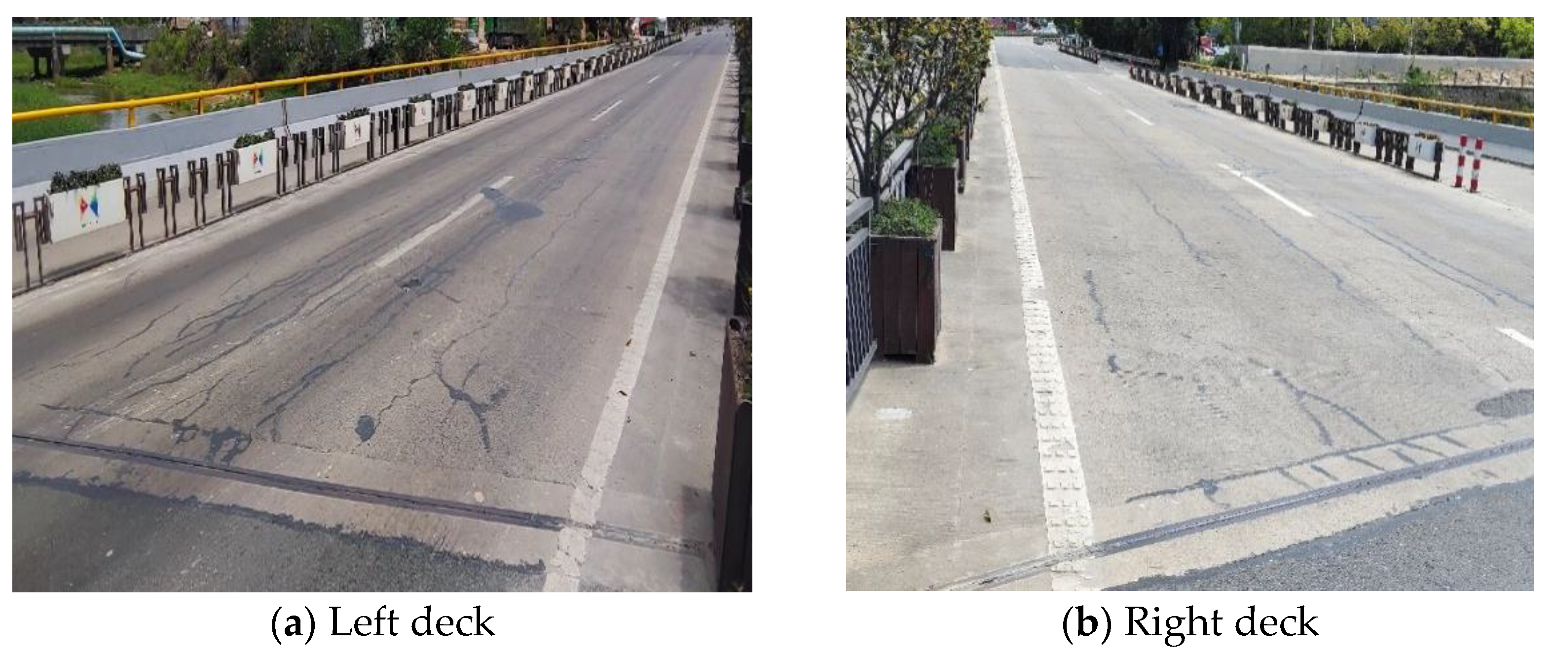
The traffic flow on the Zhuxing Bridge is relatively heavy, resulting in obvious damage to the bridge. In particular, the bridge deck pavement continued to show longitudinal cracks after multiple reinforcements, and the cracking locations basically extended along the hinge joints (Figure 2). This is consistent with the particular stress and damage commonly found in the hollow slab girder bridges. Under the long-term heavy traffic load, the pavement in the hinge joint area cracked and gradually extended. The main reason is that the replacement of the pavement layer failed to fundamentally solve the synergistic service of each hollow girder because of the weak transmission capacity of this pavement layer.
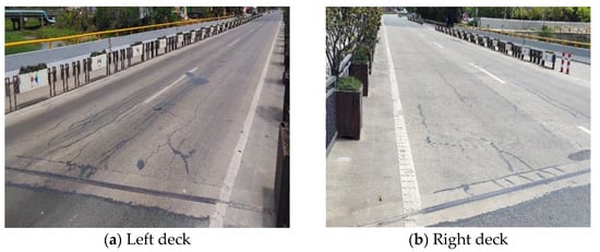
Figure 2.
Status of the pavement of the bridge.
Based on the investigation and study of the characteristics and application of UHPC, the highway management department decided to update the bridge pavement again with UHPC.
3. Structural Method of Reinforcement and Construction Stages
3.1. Theoretical Basis of Hollow Girder Reinforcement
The prefabricated slab bridges that are commonly used in China are divided into solid slabs and hollow slabs according to the section form. The span of the solid slab is small. To adapt to the larger span, the hollow slab not only reduces the weight, but also gives full play to the role of materials. Therefore, the existing slab bridge is basically a hollow slab girder.
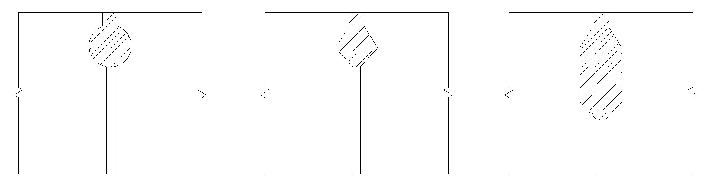
To ensure that he assembled plate girder jointly bears the vehicle load, it is necessary to set the transverse connection with sufficient strength in the transverse direction. Welded steel plate and concrete hinge connections are the most commonly used connection methods. However, due to the high cost of welded steel plate connections, the use of this application is not always practical. At present, the transverse connection of the hollow plate usually adopts a concrete hinge. The common forms of the concrete hinge are round, diamond and funnel, as shown in Figure 3. Usually, the hinge joints are filled with fine aggregate concrete. In the case of a small vehicle load, this hinge joint can theoretically ensure the transfer of the transverse shear force and ensures that each plate cooperates with the force. This is also the basis of the hinged plate method in the calculation of the transverse distribution coefficient. This method is based on the fact that the hinge joints only transmit vertical shear, and the pavement structure layer does not participate in the force [21]. The calculation model is shown in Figure 4a.
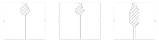
Figure 3.
Common hinge joint form of the hollow plate beam.
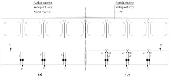
Figure 4.
Different mechanics modes of hinge joints. (a) Mechanics mode of the common hinge for transmission of shear. (b) New mechanics mode of the hinge with a stronger pavement structure. Note: P1–load; gi–shear effect by hinge; Mi–bending (moment) load effect by reinforced pavement.
Due to the structural characteristics of hollow slab girders and the long-term use of overload, the hinge joints and the integrated layer are common areas of deterioration, and these typically manifest as the fracture of hinge joints and longitudinal cracking of the integrated layer [22]. As a result, a large number of small hinge joint bridges built in the early stages, exhibit hinge joint cracking, and may form a single beam bearing load.
To strengthen the overall effect of the linkage of hinge joints, researchers in China have changed the original small hinge joints to deep hinge joints, which increases the size of the concrete joints. The rebar in the prefabricated plate can be extended and bound with adjacent rebar and then poured into the pavement layer, and the strengthened rebar is set in the hinge joints. The purpose of this design is to ensure that the adjacent girders share the force. Inspired by this method, for a large number of existing hollow girders with small hinge joints, the transverse connection can be realized through the hinge joints and the force transfer of the stronger integral layer, especially by adding or recasting the integral layer of the pavement structure method to improve the structural performance of the hollow girder bridge. The main method of reinforcing the plate top is to set a steel plate at the hinge joints to strengthen the local stiffness so that the integrity of the plate beam is restored; however, the construction is relatively complex Another method is to recast the pavement just after cleaning the damaged bridge deck, to recover the pavement and reduce the stress transfer to the hinge joints; however, this will increase the weight. Based on these two ideas, another method involves the original pavement and common concrete structure layer. The hinge joint concrete is removed and the hinge concrete is recast, and the pavement structure layer is recast with rebar. This is the method used in this study and in the implementation.
This approach changes the original calculation assumptions for the plate girder because the recast pavement structure with bars creates a stronger structure above the adjacent plates, which can withstand bending moments (Figure 4b) [23]. With the change in the stiffness of the structural layer (effected by the thickness, rebar mesh, anchorage rebar between the pavement layer and the hollow plate), other factors will affect the distribution of the force of the adjacent hollow plate.
At present, a quantitative calculation theory has yet to be elucidated, but the corresponding application effect can be proven by the mechanical properties of transverse girders. This association is manifest in the stress and deflection of adjacent beams, which is also proven by the monitoring data in this paper.
Based on the assessment of the damage and the condition of the existing bridge, the entire pavement was replaced with a UHPC pavement by removing the original concrete. Moreover, after the restoration, the elevation of the bridge surface was the same as that of the original bridge, and there was no need to adjust the elevation of the roads on both sides to ensure that the elevation was consistent.
3.2. Reinforcement Method
Different engineering methods can be applied to the replacement of the pavement layer of the hollow slab girder bridge, and they have different effects. The existing methods for the direct replacement of the bridge pavement of ordinary hollow slab girder bridges mainly include the following two methods:
- (1)
- The previous pavement layer is completely removed and replaced with UHPC and stone matrix asphalt (SMA).
The removal of the pavement layer ensures that the structural weight is basically unchanged. Combined with the UHPC performance, this method is better to improve the structural performance. At the same time, the use of more UHPC leads to an increase in cost. Additionally, there is doubt as to whether the use of thick UHPC may produce large amounts of shrinkage in the upper part of the beam, which is equivalent to the positive moment effect, thus reducing the UHPC effect [24].
In this method, it is necessary to consider the bonding and anchoring performance of the UHPC and the original structural plate and beam, and it is necessary to increase the rebar mesh and the anchoring rebar. For bridges with partial damage, it is also necessary to consider the damage of the hinge joint.
- (2)
- Partial removal of the previous pavement, which is followed by the addition of a thin layer of UHPC and SMA is added.
This method is suitable for situations in which the damage to the hinge joint is not serious. Because it does not involve the replacement of the hinge joint, only the replacement of the upper surface is needed, the corresponding amount of work is small, and the construction is fast and inexpensive.
Considering the leveling layer, the pavement removal depth and the bridge elevation, the leveling layer is combined with the reserved pavement to ensure that the replaced pavement has a consistent elevation.
When the partial pavement is retained and the original rebar grid is exposed, it is relatively simple to remove and replace it. However, this type of project is relatively rare because most bridges that need the pavement layer replaced also have the problem of hinge joint damage. At present, there is no test or engineering verification that confirms that the partial replacement of pavement ensures that the overall performance of the structure and the stress on the hinge joint will not deteriorate.
In the two construction methods mentioned above, the reliable bond between the UHPC and the existing beam concrete is the basis for the common loading bearing. Many researchers have conducted relevant studies and experiments on the bonding performance between UHPC and NC and proved that after surface chiseling and cleaning, good adhesion between UHPC and NC can be ensured, especially in the presence of rebar mesh.
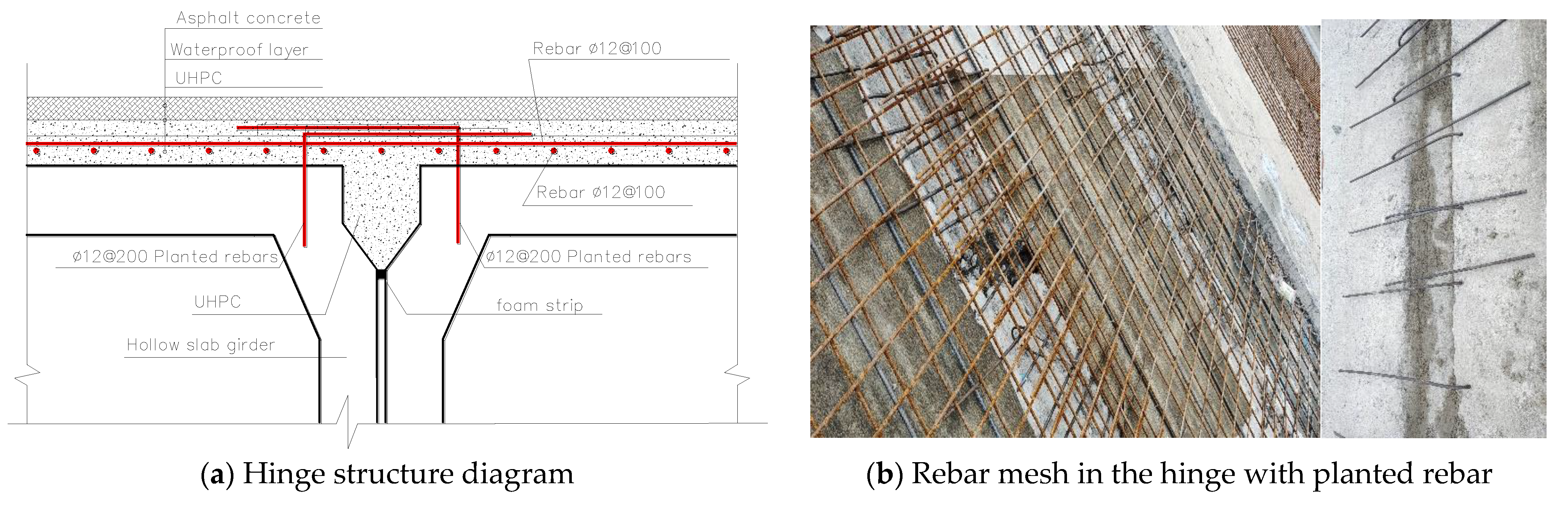
With reference to the conventional pavement structure, the pavement replacement in this project adopted the rebar mesh and hinge joint reinforcing methods at the same time. The specific design measures were as follows.
On the basis of retaining the original hinged rebar, the rebar was implanted into the web of the hollow slab girder from the top according to Φ12@200 and a rebar mesh was formed in the hinge area. In addition, a single layer of Φ12@100 × 100 rebar mesh was placed above the slab girder. The specific structure and layout are shown in Figure 5.
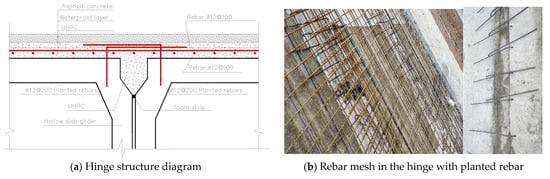
Figure 5.
Hinge and pavement reinforcement structure.
The UHPC used was UC120 grade, and the mixing ratio was powder:water:admixture:steel fiber = 1000:90.5:6.05:104.8. The specific performance parameters are shown in Table 1.

Table 1.
Technical parameters of UHPC for pavement.
3.3. Construction Stages
For the reinforcement of Zhuxing Bridge and the replacement of the bridge deck pavement, the construction process was as follows:
- (1)
- Traffic Closure
According to the traffic safety requirements, construction began at the local site and traffic protection measures were arranged. Then, the traffic access was closed off, the construction equipment was put in place, and the materials were transported to the site.
- (2)
- Removal of the top pavement and hinged concrete
For the removal of the top pavement, the damaged pavement of the bridge deck and the concrete in the hinge joint was simultaneously removed using a pick machine and manual methods. During the chiseling process, the surface of the slab girder should remain be intact. The chiseled rubbish was transported off-site, and the surface was cleaned with an air compressor to ensure that the original bridge deck and the cracked concrete were completely and cleanly removed.
- (3)
- Reinforcing bars
The original undamaged hinged rebars were retained, and the corroded or broken rebars were removed. In addition to the reserved hinged rebars, Φ12@200 hinged rebars were added using a planting method. The down-bending of the rebar was performed in the factory in advance to ensure that the down-bending size met the specification requirements (Figure 6a). The rebar was implanted in the web, and it was not allowed to penetrate the roof to the slab girder. Another rebar mesh Φ10@100 was added.
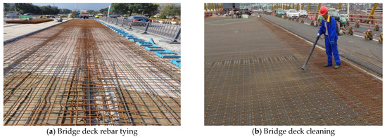
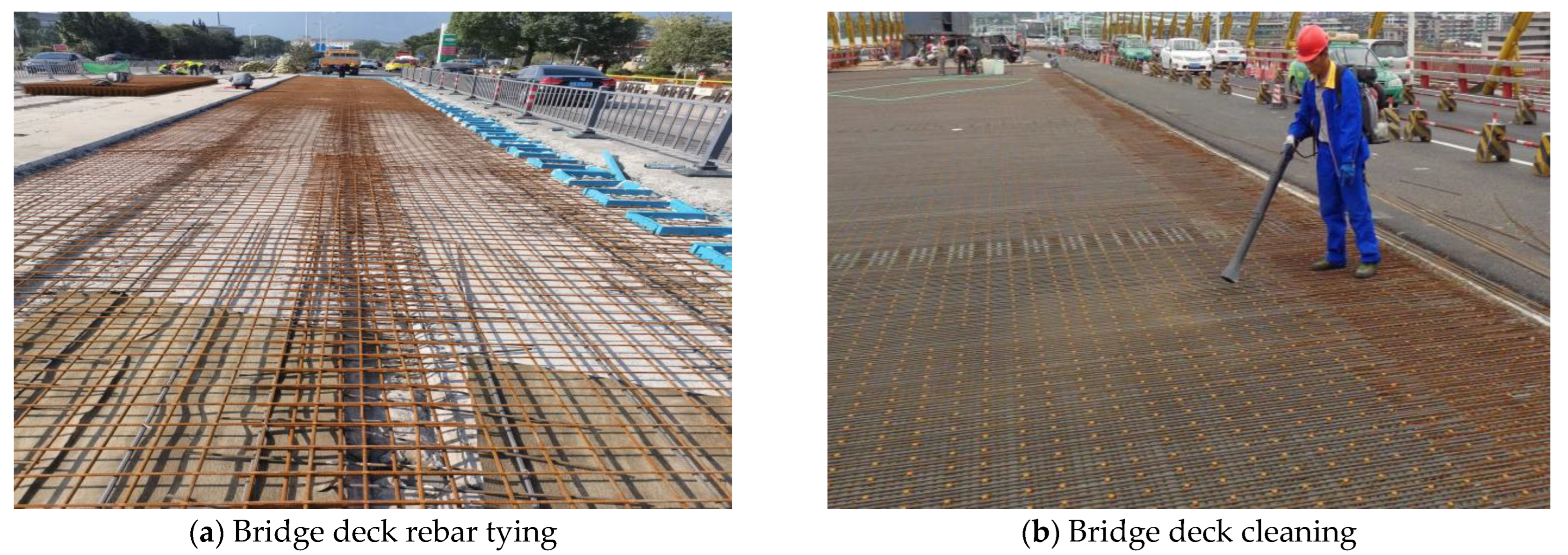
Figure 6.
Preparation before UHPC construction.
- (4)
- Laying rebar in the pavement layer
A prefabricated single-layer Φ12@100 × 100 rebar mesh is placed above the slab girder.
- (5)
- The surface of the slab girder was cleaned completely and the debris and rubbish generated by the planting rebar were removed (Figure 6b).
- (6)
- UHPC construction of the pavement layer
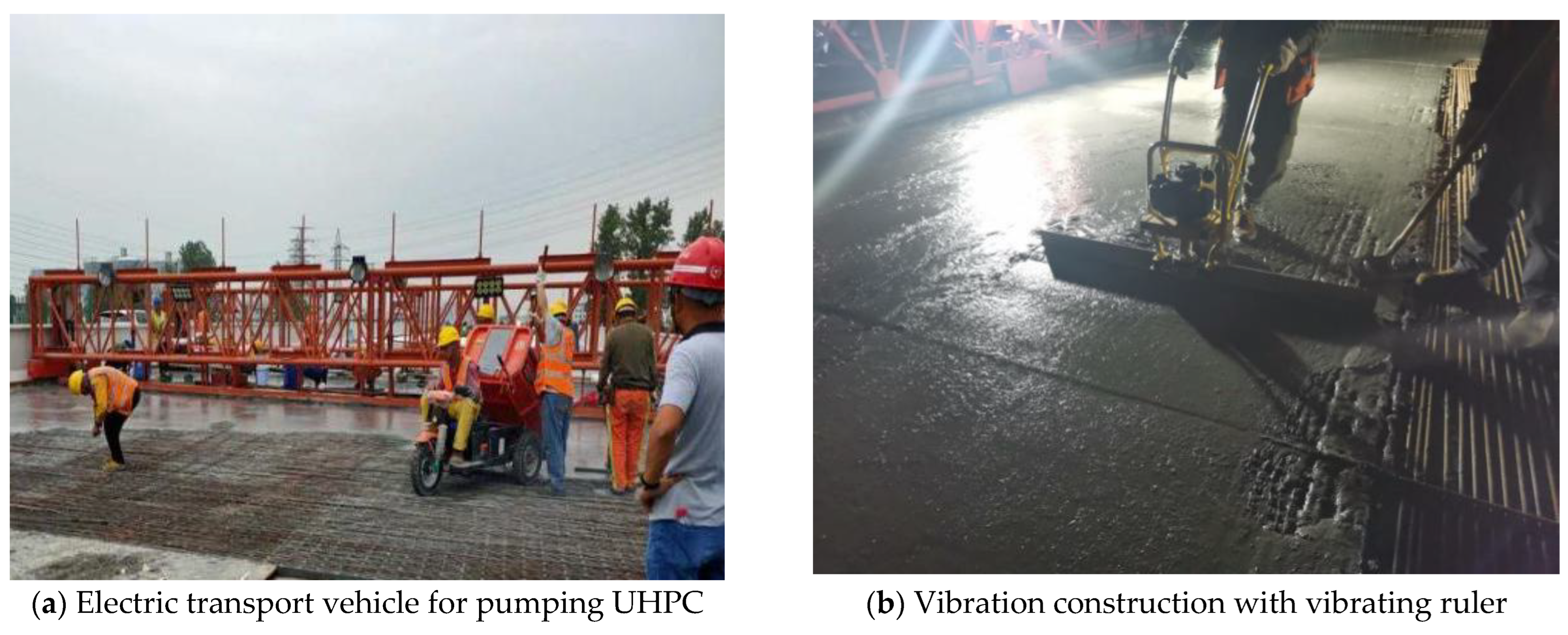
After the rebars of the bridge deck pavement were inspected and accepted and the hinged joint rebars met all the requirements, the pouring of the hinged joints and the pavement layer began. The overall principle of pavement pouring is “mixing, pouring, leveling, and covering”. The UHPC mixture was immediately distributed; then the corresponding strips were immediately vibrated and leveled (Figure 7). After completing the preliminary distribution of 2–3 strips, the vibrating ruler was used for further smoothing and vibrating. The length of the vibrating ruler should be less than or equal to 1.5 m.

Figure 7.
UHPC pavement construction.
- (7)
- Adhesive layer structure
Before the final setting of the UHPC, the aggregates, which had a diameter of 10–30 mm. were evenly distributed. The spray distribution requires 2–3 grains/10 cm2. Since there is no quantitative approach in regard to this part of the process, the above method was based on a method previously proposed for a steel deck with UHPC to increase the adhesion between the SMA and the UHPC [11,25].
- (8)
- Curing
Ten minutes after the pavement was completed, the surface of the pavement was no longer obviously sticky, and the strips were covered with a moisturizing curing film.
After the film was covered, the UHPC pavement was covered with a moisture-retaining geotextile for approximately 4 h after the initial setting. Twenty-four hours after pouring, the membrane was removed and then covered with a moisturizing geotextile for 3 days.
- (9)
- Bridge deck asphalt concrete paving construction
Special spraying equipment was used for the construction of waterproof materials.
With regarding to the density of the UHPC, theoretically, a waterproof layer is not needed here. In the current practical application process, water penetration from the construction joint cannot be excluded and given that the current lack of construction specifications cannot ensure the quality, the waterproof layer is often completely abandoned. However, considering that the pavement in this project was divided into different parts and the UHPC was poured in stages, there will naturally be numerous construction joints. In order to ensure the quality of construction, the waterproof layer was set under the UHPC layer.
The paver must be preheated for 15 min in advance. When the preheating temperature reaches 120 °C or above, it can be spread.
Sufficient material supply must be ensured, and the paving operation should be continuous.
- (10)
- Clean up the site and open it up to traffic.
4. Verification and Monitoring of the Reinforcement Effect
To verify the effect of the UHPC pavement, it is necessary to compare the usage of the bridge before and after the pavement was replaced. The most common mechanical performance index consists of comparing the deflection to assess the rigidness and using the strain to obtain the stress in order to assess the cracking or failure of the bonding.
4.1. Deflection Monitoring
The overall performance of the beam improved after the hinge joint and pavement reinforcement, and the corresponding deflection results were obvious. The deflection and stress change under the load of the structure was most obvious in the mid-span section of the beam, which reflects the improvement in the girder.
Considering that this project is a double-frame two-way four-lane structure, to reduce the monitoring workload, the lane with more heavy vehicles was selected for monitoring because it showed relatively heavy damage (longitudinal hinge joint damage and more transverse cracks in the middle of the span). The monitoring was performed on the first cross-section.
The specific deflection monitoring plan was as follows.
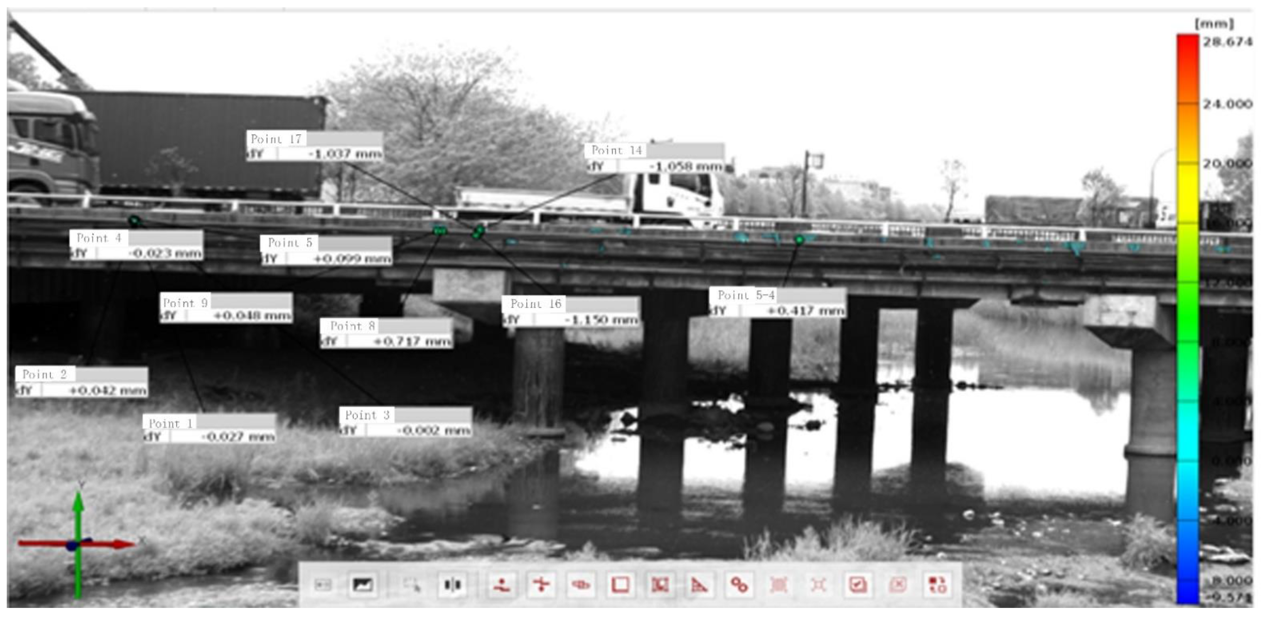
With the help of a non-contact optical deflection monitor, multiple monitoring points were placed on the left, middle, and right side of the bridge to measure the deflection of the span. We used the Germany-made “GOM” Optical 3D Deformation Analysis System (ARAMIS Professional), and the ARAMIS 3D 12M model. Figure 8 shows the side observation points that can be used for observation, while the actual observation was achieved through various points at the bottom of the bridge.

Figure 8.
Interface of the monitoring system.
The reference point was required to be lower than the destination point at the bottom of the bridge. The observation reference point was located approximately 20 m upstream of the bridge, and a concrete foundation that measured 50 cm × 50 cm × 50 cm was used. Two steel piles with a diameter of 12 cm, a wall thickness of 10 mm, and a length of 2 m were used, and the implantation depth in the foundation was 0.5 m. A steel base plate and a steel backing plate were installed on the steel pipe piles, and the steel materials were connected by welding to ensure stability.
4.2. Strain Monitoring of Hinge Joint
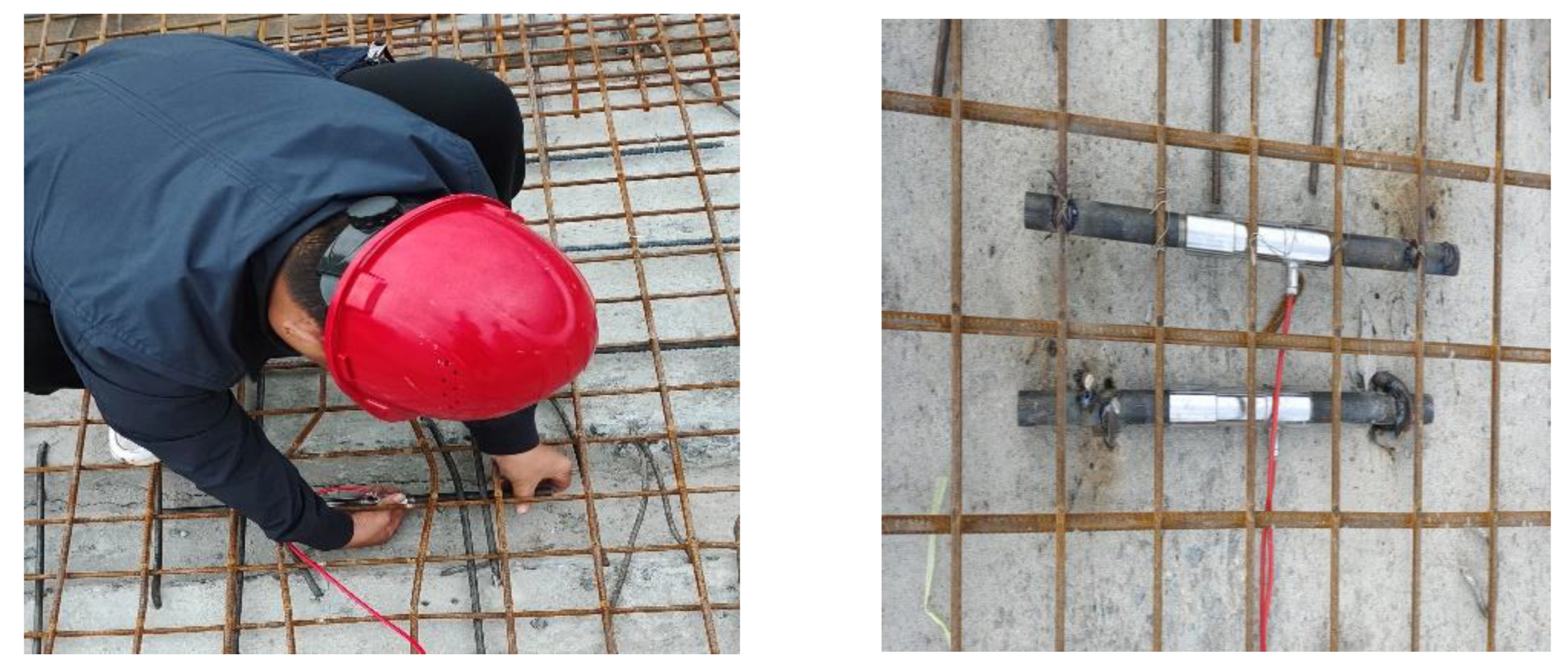
A wireless vibrating wire monitoring system was adopted to monitor the strain. The mid-span section of the girder, which is especially affected by the wheels of heavy vehicles, was selected for monitoring, and to measure the transverse double-layer vibrating wire strain. Gauges were arranged on the transverse upper rebars and the top of the UHPC hinge joint (Figure 9), which corresponded to the four hinge joints between the five inner beams of the first span. There were a total of eight rebar strain gauges and eight concrete strain gauges on the left and right sides of the bridge. The strain gauges were numbered from the inside to the outside as No. 1 to No. 4 on the left, and No. 5 to No. 8 on the right.
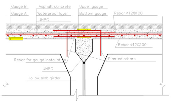
Figure 9.
Gauge arrangement plan.
4.3. Adhesion between UHPC and the Girder
Theoretically, if the bond layer is not separated, the two gauges should have the same strain value when the girder is under moment. Based on the plane section assumption, it is considered that the concrete strain at the same height is consistent. Therefore, to keep the gauges at the same height in the girder section, before UHPC pouring, it was necessary to arrange strain gauge A on the upper surface of the hollow slab girder. The most feasible method was to chisel out the top rebar of the hollow beam and fix the strain gauge to the rebar to ensure that the center was in parallel with the hollow slab girder on the upper surface (see Figure 9 and Figure 10).
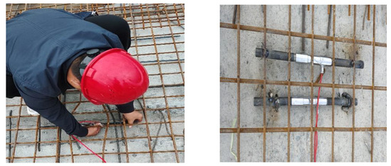
Figure 10.
Gauge installation in the adhesion layer.
Strain gauge B was fixed on the rebar in the UHPC layer, but the center of the strain gauge was located on the lower surface of the UHPC. Gauge B was placed in parallel with strain gauge A at the same location, and the distance between them was as close as possible. Figure 10 shows an image of gauge A and B located on the top of the girder.
Considering the bending effect of the simply supported beam, the potential UHPC delamination area is near the beam end. Therefore, the above measuring points were positioned on the 0.5 m cross section at the end of the beam, with an interval of 1–2 girders, and then gauge A and B are arranged at each location. A total of 10 gauges were arranged at 5 locations.
5. Data and Analysis
5.1. Strain Characteristics after Reinforcement
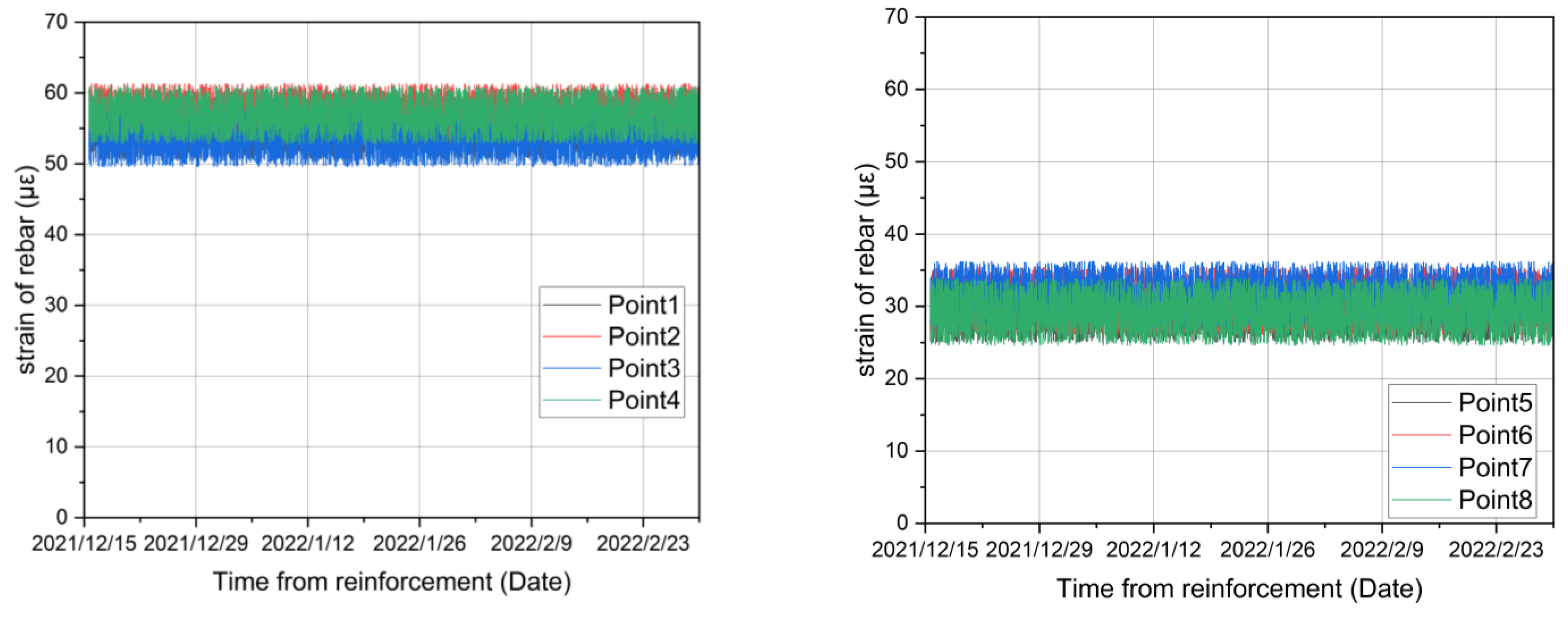
Figure 11 shows the results of monitoring the rebar strain in the three months after the completion of the construction. The strains recorded by rebar strain gauges 1 to 4 in the hinge joints on the left side of the bridge were in the range of 49~62 με, and the strains of rebar strain gauges 5 to 8 in the hinge joints on the right side of bridge were in the range of 24~37 με.
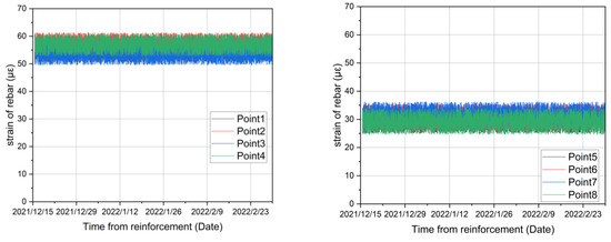
Figure 11.
Rebar strain.
The strains recorded by gauges 1 to 4 in the UHPC layer on the left side of the bridge hinge all fluctuated within 10 με. The strain range on the UHPC layer in the right side of the bridge hinge was relatively small, that is, between 35 and 55 με, of which the maximum value of the No. 5 sensor was 55 με, and the minimum value of the No. 8 sensor was 42 με (Figure 12).
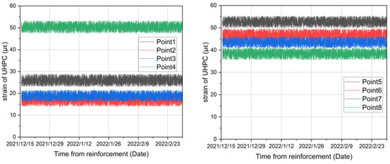
Figure 12.
UHPC strain.
According to the strain values of the beam and UHPC calculated by the adjacent strain gauges, it can be seen that the beam and the UHPC at the same position have basically the same strain characteristics, which fully proves that the UHPC and the beam have good deflection synchronization. This also proves that the deflection of the beam on both sides of the hinge joint is coordinated, and the force on the hinge joint achieves a good load transfer function through the transition of the UHPC.
5.2. Changes in Structural Stiffness after Reinforcement
According to the actual situation of the site, the vibration of the bridge slab was monitored under normal traffic conditions. During monitoring, data were collected every 5 min. The data collected from 12 measurement points were randomly selected for analysis, and the maximum amplitude of the structure before and after reinforcement was obtained. The values and minimum and average values are shown in Table 2.
Table 2.
Maximum amplitude of deck before and after reinforcement (unit: mm).
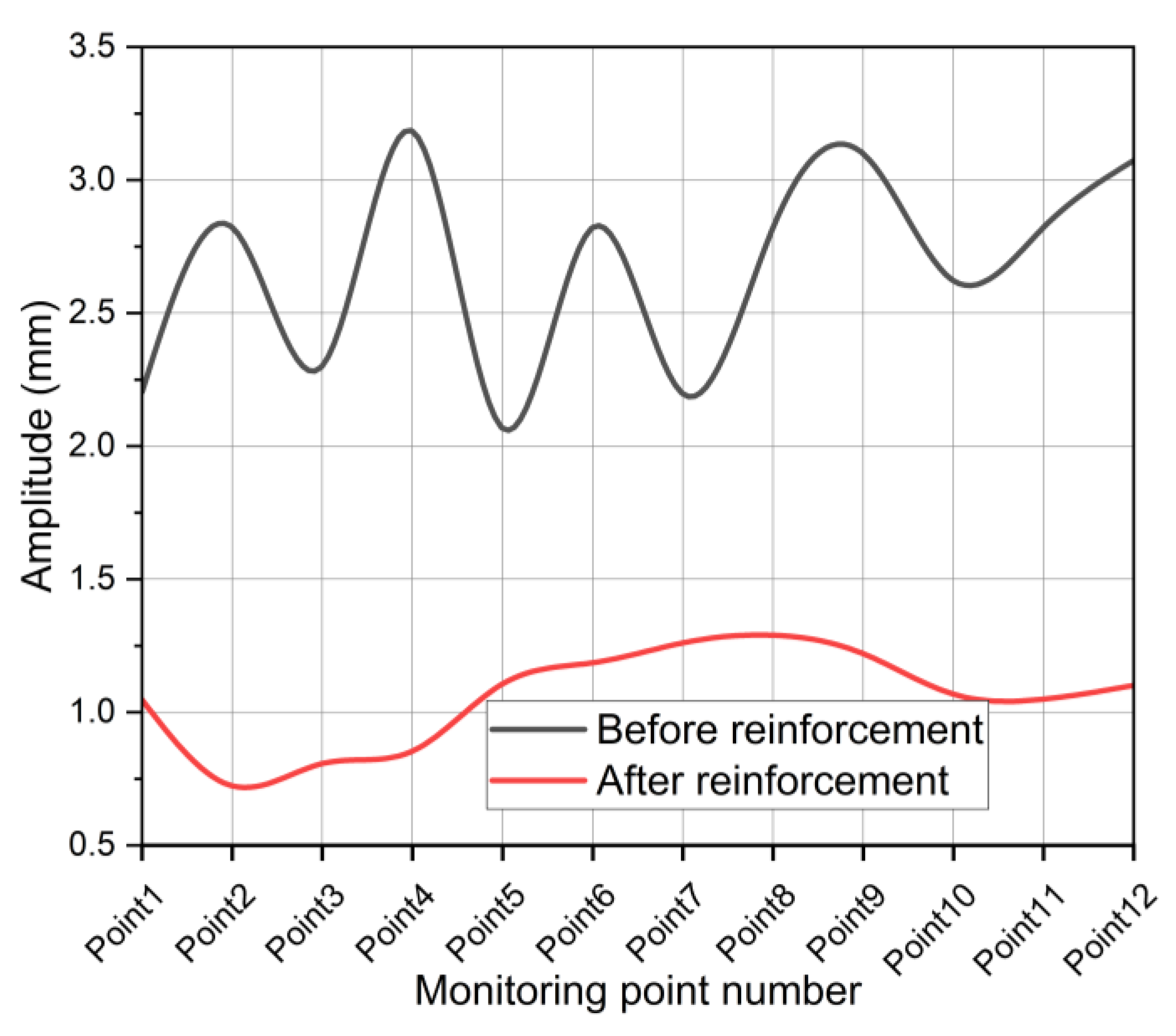
Figure 13 shows that the maximum amplitude of the bridge deck before reinforcement was greater than 2 mm, and the maximum amplitude of the bridge deck reached more than 3 mm. Among the 12 randomly selected monitoring points, the maximum amplitude of each point was different. The graph below shows obvious ups and downs, indicating that before the bridge deck was reinforced, the bridge deck had significant deflection under normal traffic conditions.
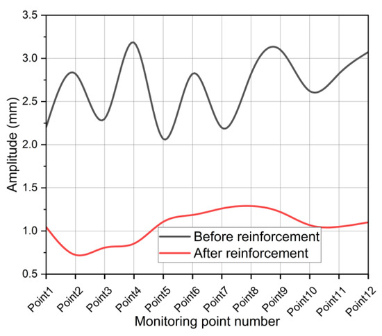
Figure 13.
Maximum amplitude of bridge deck before and after reinforcement (unit: mm).
After the bridge deck was reinforced, the maximum values of the 12 selected monitoring points under normal traffic conditions were relatively small. It can be clearly seen from the graphs that the maximum values after reinforcement do not exceed 1.5 mm. The curve undulates smoothly, and there is no obvious undulation, which indicates that after the bridge deck was reinforced, the maximum amplitude of the bridge deck decreased compared to that before the reinforcement, and the UHPC reinforcement had a significant effect.
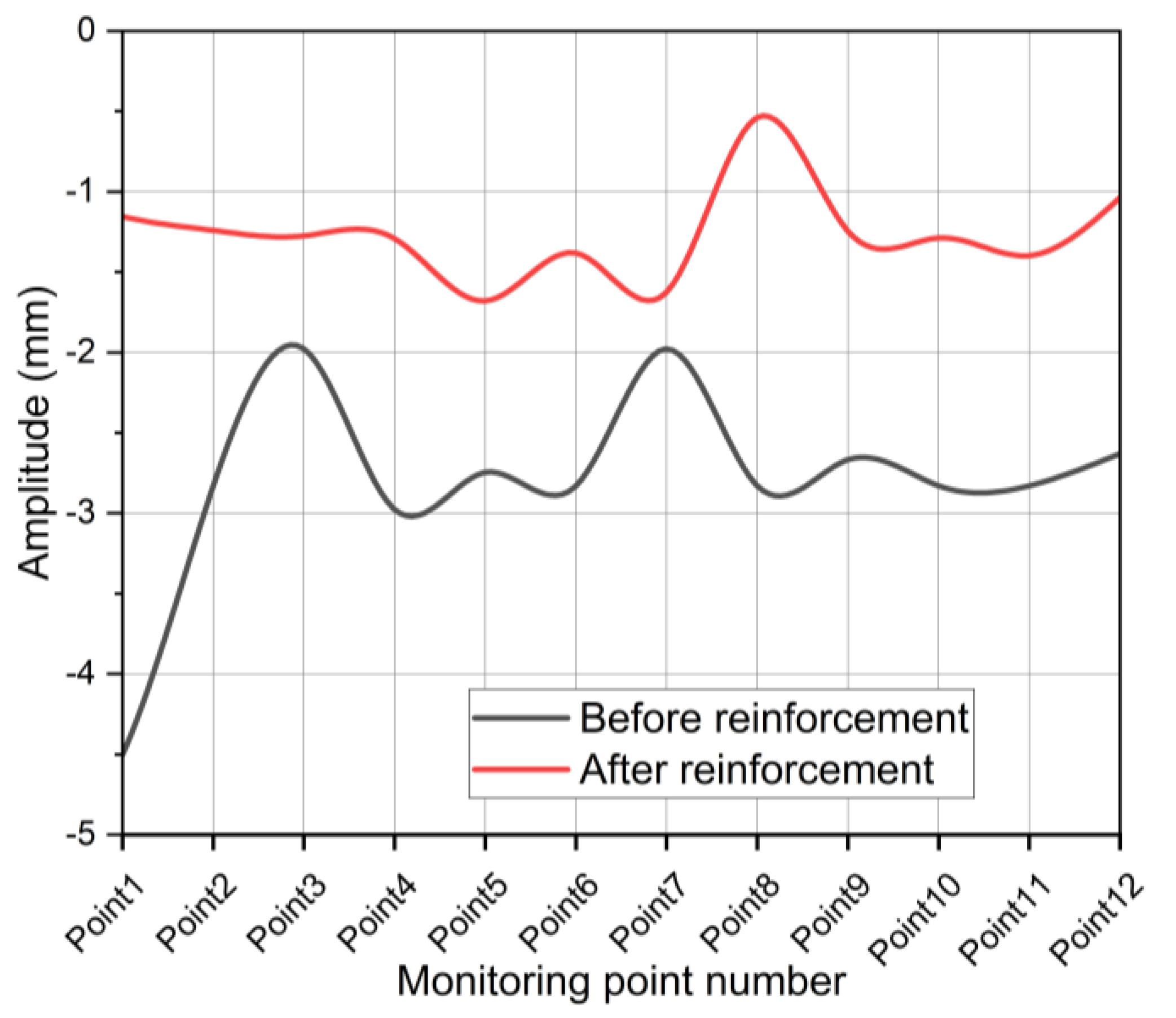
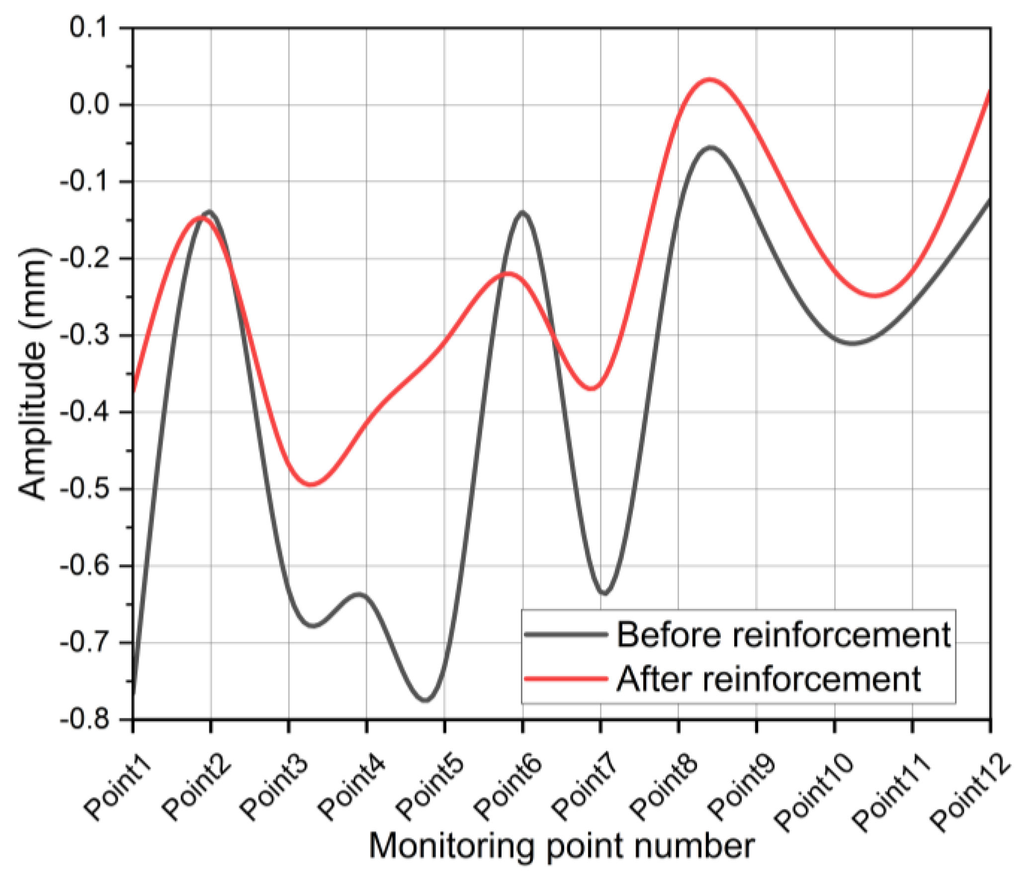
Figure 14 shows that the minimum amplitude of the bridge deck before the reinforcement reached −4.5 mm and stayed below −2 mm. Among the 12 randomly selected monitoring points, the minimum amplitude of each point was different. The associated curve has obvious ups and downs, indicating that before the bridge deck was reinforced, under normal traffic conditions, the bridge deck had significant deflection after being compressed. Similarly, after the bridge deck was reinforced, the minimum values of the 12 selected monitoring points under normal traffic conditions were relatively small. Except for point 8, the minimum values after reinforcement did not exceed −1.7. The undulation of the curve is gentler than that before the reinforcement, which also indicates that the minimum amplitude of the bridge deck after the reinforcement decreased compared to that before the reinforcement, and the use of UHPC had a significant effect on the reinforcement.
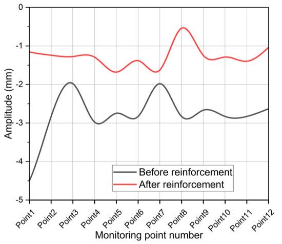
Figure 14.
Comparison of minimum amplitude before and after reinforcement.
Figure 15 shows the comparison of the results of the average amplitude before and after the reinforcement of the bridge deck.
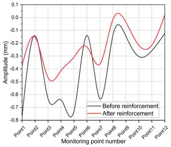
Figure 15.
Average amplitude before and after reinforcement.
According to the average value of the 12 monitoring points, it can be clearly seen that the amplitude of each point is different before reinforcement, and the difference in the average values is also large. Therefore, the curves in the wave are relatively large, which indicates that the stability of the bridge deck was poor. After the bridge deck was strengthened, the amplitude of the curve was relatively large compared with that before the reinforcement. Although the beam located in the lane fluctuated more, the overall deflection was still relatively gentle, proving that the bridge deck had a better reinforcement effect.
6. Conclusions
- (1)
- The designed bridge deck pavement adopted 8 cm thick UHPC and 4 cm modified asphalt concrete pavement, the transverse load-bearing performance of the beam slab was enhanced, and the overall bearing capacity was improved. Based on the conclusions of other researchers and the performance of UHPC, the UHPC thickness can be optimized.
- (2)
- Several researchers have already proved that the effect of planting reinforcement on the joint surface between the UHPC and the main girder is significant. This allows the original concrete layer and the UHPC layer to be more closely connected. Rebars planted at the hinge joint with UHPC greatly improve the transmission capacity of the transverse force between the slab girders.
- (3)
- In terms of the performance of the bond between the UHPC and the bridge, according to the stress analysis of the monitored rebar and UHPC, the change in the stress on the hinge joint was mainly tensile at less than 55 με and the amplitude was less than 10 με. Judging from the similarity of the strains of the two types of gauges, the rebar and the UHPC maintain a good synergistic effect.; The shear deflection of the hinged joint due to the change in the beam was not obvious, which proves that the UHPC pavement had a positive impact.
- (4)
- Monitoring the amplitude of the reinforced bridge deck proved that the overall performance of the bridge reinforced with UHPC was significantly improved. The minimum and maximum amplitudes after reinforcement (minimum −1.5~−1.0 mm, maximum 0.75~1.25 mm) were reduced by half compared to before reinforcement (minimum: −3.0~−2.0 mm, maximum 2.0~3.0 mm).
- (5)
- The improvement in the flatness of the bridge surface has a positive effect on reducing bridge vibration. The resistance to the deformation of the UHPC pavement layer was relatively excellent, and the bond between the UHPC and girders was also very strong without delamination. It should be noted that the bridge pavement and hinge joints were repaired at the same time, which affected their respective contributions to a certain extent.
- (6)
- Since the reinforced pavement with reinforced hinges already increased the mechanical performance and affected the load distribution of each girder, the new theoretical calculation method for the live-load distribution factor should be restudied. The monitoring data from real bridges can play an auxiliary role in static load testing to verify the theoretical method.
Author Contributions
Conceptualization, W.Y. and F.L.; methodology, F.L.; validation, W.Y.; formal analysis, W.Y.; investigation, W.Y.; resources, W.Y.; data curation, W.Y.; writing—original draft preparation, W.Y.; writing—review and editing, W.Y.; visualization, W.Y.; supervision, F.L.; project administration, W.Y.; funding acquisition, W.Y. All authors have read and agreed to the published version of the manuscript.
Funding
Ningbo Transportation Science and Technology Project (No.: 202108).
Institutional Review Board Statement
Not applicable.
Informed Consent Statement
Not applicable.
Data Availability Statement
The data used to support the findings of this study are included within the article.
Conflicts of Interest
The authors declare that they have no conflict of interest.
References
- Miyamoto, A.; Kiviluoma, R.; Yabe, A. Frontier of continuous structural health monitoring system for short & medium span bridges and condition assessment. Front. Struct. Civ. Eng. 2019, 13, 569–604. [Google Scholar] [CrossRef]
- Zhang, B.; Zhu, D.; Xu, J.-W.; Tian, H. Overall Situation and Typical Diseases of Medium and Small Span Concrete Bridges in Zhejiang Province. J. Chongqing Jiaotong Univ. (Nat. Sci.) 2013, 32, 742–745. [Google Scholar]
- Huang, P.M.; Wang, J.F.; Han, W.S.; Yuan, Y.G. Study on impact factors of small- and medium-span bridges under the special-purpose vehicle load. Structures 2022, 43, 606–620. [Google Scholar] [CrossRef]
- Gao, Q.F.; Wu, B.; Li, J.; Cui, K.M.; Xu, C. Investigation of Traffic Loading Effects for Different Codes on Medium- and Small-Span Girder Bridges in China. Adv. Civ. Eng. 2020, 2020, 8851981. [Google Scholar] [CrossRef]
- Szafranski, M. Dynamics of the small-span railway bridge under moving loads. Matec. Web Conf. 2019, 262, 10014. [Google Scholar] [CrossRef]
- Looney, T.; Volz, J.; Floyd, R. Behavior of a 3-Span Continuous Bridge Before and After Continuity Joint Replacement Using Ultra-High-Performance Concrete. J. Perform. Constr. Fac. 2021, 35, 04021087. [Google Scholar] [CrossRef]
- Lu, Z.; Feng, Z.G.; Yao, D.D.; Li, X.J.; Jiao, X.L.; Zheng, K.X. Bonding performance between ultra-high performance concrete and asphalt pavement layer. Constr. Build. Mater. 2021, 312, 125375. [Google Scholar] [CrossRef]
- Shemirani, A.B. Experimental and numerical studies of concrete bridge decks using ultra high-performance concrete and reinforced concrete. Comput. Concr. 2022, 29, 407–418. [Google Scholar]
- Huang, Y.; Chen, S.M.; Gu, P. Interface stress analysis and fatigue design method of steel-ultra high performance concrete composite bridge deck. Structures 2022, 38, 1453–1464. [Google Scholar] [CrossRef]
- Yang, J.; Hou, P.; Pan, Y.; Zhang, H.L.; Yang, C.Q.; Hong, W.; Li, K.F. Shear behaviors of hollow slab beam bridges strengthened with high-performance self-consolidating cementitious composites. Eng. Struct. 2021, 242, 112613. [Google Scholar] [CrossRef]
- Chen, S.; Visintin, P.; Oehlers, D.J. Bond between very-high and ultra-high performance fibre reinforced concrete and profiled deck sheeting. J. Build. Eng. 2022, 52, 104426. [Google Scholar] [CrossRef]
- Harris, D.K.; Sarkar, J.; Ahlborn, T.M. Characterization of Interface Bond of Ultra-High-Performance Concrete Bridge Deck Overlays. Transp. Res. Rec. 2011, 2240, 40–49. [Google Scholar] [CrossRef]
- Bruehwiler, E. Renewal of reinforced concrete bridges by means of UHPFRC. Beton Stahlbetonbau 2022, 117, 720–732. [Google Scholar] [CrossRef]
- Bertola, N.; Schiltz, P.; Denarie, E.; Bruehwiler, E. A Review of the Use of UHPFRC in Bridge Rehabilitation and New Construction in Switzerland. Front. Built Environ. 2021, 7, 769686. [Google Scholar] [CrossRef]
- Valikhani, A.; Jahromi, A.J.; Mantawy, I.M.; Azizinamini, A. Experimental evaluation of concrete-to-UHPC bond strength with correlation to surface roughness for repair application. Constr. Build. Mater. 2020, 238, 117753. [Google Scholar] [CrossRef]
- Liu, C.; Ji, H.; Wang, J.; Luo, P. The new strengthening method of hollow slab girder bridges by uhpc. In Symposium on Ultra-High Performance Fibre-Reinforced Concrete: Designing and Building with UHPFRC: New Large-Scale Implementations, Recent Technical Advances, Experience and Standards; Toutlemonde, F., Resplendino, J., Eds.; RILEM Publications SARL: Montpellier, France, 2017; pp. 675–682. [Google Scholar]
- Zhang, S.; Du, S.; Ang, Y.; Lu, Z. Study on performance of prestressed concrete hollow slab beams reinforced by grouting with ultra-high performance concrete. Case Stud. Constr. Mater. 2021, 15, e00583. [Google Scholar] [CrossRef]
- Muzenski, S.; Haber, Z.B.; Graybeal, B. Interface Shear of Ultra-High-Performance Concrete. Aci. Struct. J. 2022, 119, 267–280. [Google Scholar] [CrossRef]
- Zhang, Y.; Wu, J.; Shao, X.; Hou, C. Experiment on interfacial shear properties between ultra-high performance concrete and normal strength concrete. China Civ. Eng. J. 2021, 54, 81–89. [Google Scholar]
- De Domenico, D.; Messina, D.; Recupero, A. Quality control and safety assessment of prestressed concrete bridge decks through combined field tests and numerical simulation. Structures 2022, 39, 1135–1157. [Google Scholar] [CrossRef]
- Guo, J.; Xu, F.; Kang, L.; Li, G.; Liu, F.; Jin, Z. Lateral Distribution Calculation and Bearing CapacityAnalysis of Hollow Slab Girder Bridge Considering Integral Layer. Struct. Eng. 2021, 37, 194–199. [Google Scholar] [CrossRef]
- Sun, H.F.; Wu, Z.G.; Kang, A.H.; Gu, W.; Shen, Q.; Zhang, R.J. Research on Damage of Hinge Joint of Concrete Hollow Slab Beam. J. Henan Univ. Sci. Technol. (Nat. Sci.) 2021, 42, 57–63. [Google Scholar] [CrossRef]
- Ding, Y.; Wang, X.D.; Shi, M.S.; Lu, P.Z.; Li, D.G. Influence of Hinge Joint Damage on Transverse Force Transfer of Hollow Slab Girder Bridge. China Munic. Eng. 2021, 218, 96–99. [Google Scholar] [CrossRef]
- Orta, L.; Bartlett, F.M. Sensitivity analysis of restrained shrinkage stresses of concrete deck overlays. Eng. Struct. 2020, 210, 110396. [Google Scholar] [CrossRef]
- Zhang, H.; Zhang, Z.X.; Gao, P.W.; Cui, L.; Pan, Y.Q.; Li, K. Performance of steel bridge deck pavement structure with ultra high performance concrete based on resin bonding. Front. Struct. Civ. Eng. 2021, 15, 895–904. [Google Scholar] [CrossRef]


Publisher’s Note: MDPI stays neutral with regard to jurisdictional claims in published maps and institutional affiliations. |
© 2022 by the authors. Licensee MDPI, Basel, Switzerland. This article is an open access article distributed under the terms and conditions of the Creative Commons Attribution (CC BY) license (https://creativecommons.org/licenses/by/4.0/).