Article

Attitude Error and Contact Influencing Characteristic Analysis for a Composite Docking Test Platform

Key Laboratory of Advanced Manufacturing and Intelligent Technology, Ministry of Education, Harbin University of Science and Technology, Harbin 150080, China
*
Author to whom correspondence should be addressed.
Appl. Sci. 2022, 12(23), 12093; https://doi.org/10.3390/app122312093
Submission received: 17 October 2022 / Revised: 5 November 2022 / Accepted: 7 November 2022 / Published: 25 November 2022

Abstract

:
The design and analysis of a new type of three-jaw docking mechanism capable of space rendezvous and docking are presented. In addition, a composite docking test platform capable of both vertical and horizontal docking is created. On the basis of kinematics theory, a global coordinate system is built, and the attitude error is assessed based on the error angle. On the basis of dynamic theory, the multi-body dynamic differential equation of the composite docking platform is derived, and the impact-induced interaction state of the locking pawls is studied. The simulation software is then used to jointly simulate the test platform and the docking mechanism under the two conditions of frontal and oblique docking, and to analyze the attitude law caused by the change of docking impact force. This provides a solid foundation for future research into the application of space rendezvous theory to small spacecraft.

1. Introduction

With the expansion of human space travel, rendezvous and docking technology in spacecraft have become indispensable for a variety of space activities [1,2]. When conducting docking activities in space, active and passive docking mechanisms must attain and maintain high levels of reliability and stability. Inspection and acceptance of the ground test platform should ensure the platform’s high dependability and stability [3]. Currently, it is customary to employ a semi-physical simulation test platform to conduct a large number of ground-docking simulation experiments in order to thoroughly examine the entire spacecraft docking process [4]. This method can be used to replicate docking studies involving vehicles with varying initial attitudes and surroundings. In addition, it can be used to test the functioning of each subsystem and device incorporated into the docking procedure, as well as to confirm the initial attitude of the spacecraft during docking to assure the effective completion of the space docking task [5]. The ground-docking simulation test platform is becoming increasingly significant as the major test equipment for developing and evaluating the docking mechanism and space docking technologies. Therefore, its ongoing development and renewal is essential. Even though there are numerous types of semi-physical simulation test platforms, only vertical or horizontal single-mode docking tests can be conducted. The inability to conduct docking experiments with different docking modes on the same test platform hinders the design and development of the docking mechanism. In addition, with only a vertical or horizontal single-mode docking test, a more comprehensive examination of docking technology, which advances research on space docking technology, remains a blind spot [6].
In the study of spacecraft attitude error, corresponding research has been undertaken. The space docking mechanism has drawn the interest of numerous countries doing aerospace-related scientific research. As the linchpin technology of docking and capturing mechanisms, all nations have conducted extensive research on it and attained specific achievements. The docking form adopted by the on-orbit capture device of the United States’ “Orbit Express” space autonomous operation system is a trident-shaped docking mechanism. The direct capture technique is distinguished by its light weight, outstanding performance, and strong orbital maneuverability [7]. The United States and Russia utilized the cone-type docking mechanism in their early docking practices, including the lunar landing program, the “Skylab” project, and the design of the “Soyuz” manned spacecraft. After ongoing development, a relatively finished docking mechanism was created. It is used extensively in significant space equipment, such as the “Progress” cargo spacecraft, “Salute,” and “Mir” space station [8,9,10]. In addition to the docking mechanisms listed above, there are numerous configurations of docking mechanisms, such as the end of the Japanese-developed actuators ERA and ARH being equipped with a variety of sensors, which can greatly enhance the safety and flexibility of docking and perform precise operations such as fuel filling and module maintenance [11,12,13]. The Canadian-developed dexterous hand SPDM motion manipulator is mounted on the space station remote control manipulator system (SSRMS) [14,15,16,17]. ESA’s three-degrees-of-freedom horizontal docking simulation test bench consists of an active test platform, a gravity balance mechanism, and a docking mechanism [18,19,20], etc. In most cases, a collision will result in a linkage reaction mechanism, and the dynamic performance parameters are obtained via the multiple buffer feedback devices arranged in [21]. The equipment is primarily used in the research center [22,23,24] to simulate various typical state changes during the docking and separation process, such as collision and stability regression. The five-degrees-of-freedom, rope-type comprehensive docking test bench is mostly utilized for dynamic testing and verification of the actual model. The model is suspended on a three-level hinge suspension rope [25,26,27] to maintain its center of mass position. It has been utilized in the “Apollo” and “Soyuz” docking verification test [28]. The bottom tracking mechanism of the six-degree-of-freedom hybrid comprehensive test bench in the United States is designed with a hydraulic buffer to enable irregular six-degree-of-freedom motion [29,30,31]. Its upper platform is fitted with a number of sensors for determining the docking status. On the basis of the theoretical model, this type of test bench can examine various parameter value changes in the actual docking scenario [32], as well as simulate and test the butt joints of asymmetric structures at various temperatures [33,34].
Harbin University of Technology researchers have proposed a new attitude description method and a representation method of gaze error, which directly takes the angle between the optical axis and the target vector as the error variable, establishes the error kinematics equation, and applies it to agile spacecraft in order to observe more targets [35]. Using hyperbolic tangent function, potential function, and linear sliding mode function, Li Xuehui of Harbin University of Technology creates a new sliding mode surface function and designs a collision avoidance tracking controller; the closed-loop system is asymptotically stable [36]. Wang Ming, a professor at Northwestern Polytechnic University, uses the sumo/front project of the United States as a backdrop to study the key technical problems related to attitude takeover control after space robot target capture, in order to provide theoretical support for future on orbit services such as satellite life extension, runaway satellite rescue, and orbital waste cleaning [37]. Chinese academics have proposed a robust control algorithm for tracking the attitude of the spacecraft during time-dependent rendezvous, which can ensure the accuracy of the tracking algorithm of the spacecraft during time-dependent rendezvous [38]. Chinese scholars such as Qu Zhiyong expounded the topological structure of the nine degree of freedom motion system and the establishment process of low order body array, analyzed the basic law of the system with error motion, proposed the construction method of adjacent body characteristic matrix, and studied the comprehensive spatial error of the nine degree of freedom motion system based on the characteristics of adjacent bodies. Numerous scholars from several nations have conducted extensive research on collision features [39]. Lu Shouzhao investigated the impact of historical events on the formation process on the collision characteristics of S-shaped structural components. According to the change in thickness, equivalent plastic strain, and residual stress and strain resulting from the stamping operation, the related collision models were developed, calculated, and assessed [40]. Gao Qinhe utilized the “separation collision” two-state model and the nonlinear spring damping force function to simulate the collision process between piston rods. He also established the dynamic model of an erecting multi-rigid body system that accounts for collision and simulated the motion process of a multi-stage oil cylinder. The simulation results demonstrate the effect of collision on the stability of large-scale device erection, laying the groundwork for the design of a rapid erection system [41]. Ballistic impact tests were conducted at impact speeds of 75 M/s, 105 M/s, 154 M/s, and 183 M/s using a composite material proposed by Mahesh and other researchers. Ref. [42] evaluated the energy absorption and damage mitigation properties of the proposed fiber metal elastomer three-layer composites. Rajkumar, Mahesh, and other researchers analyzed the low velocity impact (LVI) response of sisal natural rubber (NR) based flexible green composites with two different stacking sequences: sisal/rubber/Sisal (SRS) and sisal/rubber/Sisal/rubber/Sisal (SRS). Using hemispherical and conical impactors, the effect of impactor shape on the LVI response of the proposed composites was evaluated. Due to the inclusion of a compliant matrix, the proposed composites exhibit improved energy absorption and damage resistance [43]. Mahesh, Joladarashi, and other academics have investigated the mechanism that controls the damage in the proposed target. The ballistic impact test is conducted by launching a conical projectile at low range using air cannon equipment. On the basis of energy absorption and damage mechanism, the ballistic impact response of pure jute fabric and the proposed flexible composite were studied [44].
In conclusion, while the attitude error of spacecraft has been examined, there is no theory and design for composite docking based on a big angle. In addition, even though the research on collision models is quite extensive, the research based on weightlessness in space and low temperatures has not been documented. A new three-claw docking mechanism and a composite docking test platform capable of vertical and horizontal docking are designed in light of the aforementioned situation in order to satisfy the actual needs of space rendezvous and docking of small spacecraft. The joint configuration test simulation is performed to investigate the characteristics of attitude error and contact influence. The attitude error is investigated based on the kinematics theory, and the global coordinate system, error angle, and the model of double-layer sliding platform are constructed. Utilizing dynamic theory, the interaction state of the impact force of the locking claw is investigated, and its dynamic differential equation is derived. The action law of impact force is produced by concurrently simulating and analyzing the test platform and docking mechanism under the two docking situations (front and oblique) using Adams.

2. Configuring the Composite Docking Test Platform

Figure 1 is a diagram of the combined test assembly of a composite docking test platform with a three-jaw docking mechanism that supports both vertical and horizontal docking (Figure 1a and Figure 1b, respectively). Active and passive docking methods are placed via stiff connectors on active and passive motion simulators, respectively.
Figure 1a demonstrates that, following the establishment of initial circumstances, the location of the active motion simulator was fixed, and the passive motion simulator was utilized as the follow-up system to support the passive docking mechanism. During the docking process, the ball joint, spindle balance assembly, and end effector of the passive motion simulator generate a displacement velocity towards the center of mass of the active docking mechanism; here, the passive docking mechanism simultaneously rotated around the center of the ball under the action of the jaws; the entire docking test has been completed, and the posture is depicted in Figure 1b. Lastly, throughout the docking process, there is always a contact effect between the two docking mechanisms.

3. Analysis of the Composite Docking Test Platform

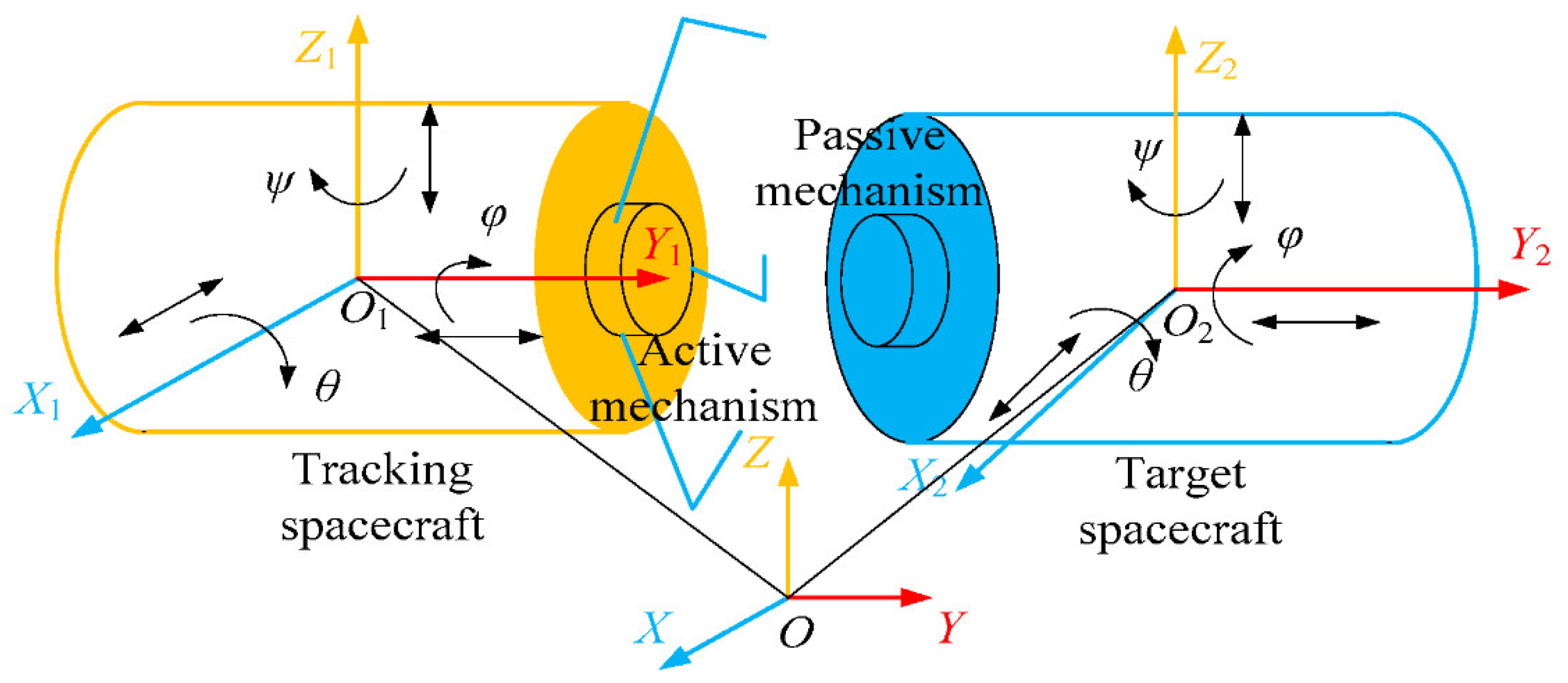
3.1. Analyzing the Space Docking Process

After the target spacecraft and tracking spacecraft have reached about the same speed and location on the track, the active docking mechanism on the tracking spacecraft extends to grab the passive docking mechanism on the target. Next, the two spacecraft were linked flawlessly using buffering and locking. The space docking was then concluded [30]. As depicted in Figure 2, the space docking procedure was performed in perfect weightlessness with three degrees of freedom and three degrees of rotational flexibility for both the target and tracking spacecraft. Consequently, the space docking process between the two spacecraft is a dynamic process with 12 degrees of freedom (That is, displacement and rotation along the x-axis, displacement and rotation along the y-axis, and displacement and rotation along the z-axis), making it very difficult for ground semi-physical simulation test systems to measure the attitude.
Realizing the relationship between the simulator’s relative position and attitude facilitated the simplification of each spacecraft’s freedom of movement. Thus, a motion simulator with six degrees of freedom and both vertical and horizontal docking modes can be created and used to model docking attitudes for various space modes. Here, the motion simulator was separated into active and passive simulators; the active simulator can realize two degrees of freedom, while the passive simulator can realize four degrees of freedom.

3.2. Attitude Error Analysis and Modeling

3.2.1. Attitude Angle Error Analysis and Modeling

Attitude angle error refers to the error in the spatial attitude of the passive docking mechanism. The passive docking mechanism was mounted on a flange plate at the end of the passive motion simulator, while the transformation of the attitude angle was achieved by the rotation of the spherical joint. Therefore, the rotation angle error of the spherical joint and coupling motion error of each rotation angle were the primary causes of the attitude angle error. The motion error of the conversion mechanism simultaneously affects the attitude angle of the docking mechanism when the composite docking test platform was free to convert between vertical and horizontal docking modes.
As shown in Figure 3, coordinate system-oxyz is established whose center was located at the centroid of the passive docking mechanism.
The docking mechanism rotates α, β, and γ around z, x, and y to successively reach o x y z ; therefore, the transformation matrix of the attitude angle is:
[ x y z ] = [ cos γ cos α sin α cos γ sin α sin β sin α cos γ + cos β sin γ sin β cos α sin β sin α sin γ + cos β cos γ cos β sin α cos γ + sin β sin γ cos β cos α cos β sin α sin γ + sin β cos γ ] [ x y z ]
According to Formula (1) [45], under ideal conditions, the change in attitude angle attained by rotating the passive docking mechanism corresponded to the change in rotation angle at the spherical joint. Consequently, we determined a relationship between the attitude angle and the rotation angle of the spherical joint as follows:
{ α = arctan ( tan ψ sec θ ) β = arcsin ( sin θ cos ψ ) γ = arctan ( tan φ tan θ sin ψ 1 + tan φ tan θ sin ψ )
Among these were the generalized rotation angles of the simulator of passive motion as it rotated about the x, y, and z axes. Since the origins of the moving and stationary coordinate systems coincided and the axis directions coincided with the axes of the original coordinate system, Formula (2) is obtained by putting it into the space Euler angle rotation formula.
In addition, when the rotation angles of the spherical joint are in errors, the attitude angles are as follows:
{ α = arctan [ tan ( ψ + Δ ψ ) sec ( θ + Δ θ ) ] β = arcsin [ sin ( θ + Δ θ ) cos ( ψ + Δ ψ ) ] γ = arctan [ tan ( φ + Δ φ ) tan ( θ + Δ θ ) sin ( ψ + Δ ψ ) 1 + tan ( φ + Δ φ ) tan ( θ + Δ θ ) sin ( ψ + Δ ψ ) ]
Frictional wear during the operation of the spherical joint can induce non-orthogonality between the X2, Y2, and Z2 axes depicted in Figure 2; nevertheless, Equation (3) defined the attitude error of the passive docking mechanism without taking this wear into account. We determined from the equation that the mistake has no effect, thus reducing the difficulty of assessing coupling motion errors and providing the technical foundation for future theoretical research.

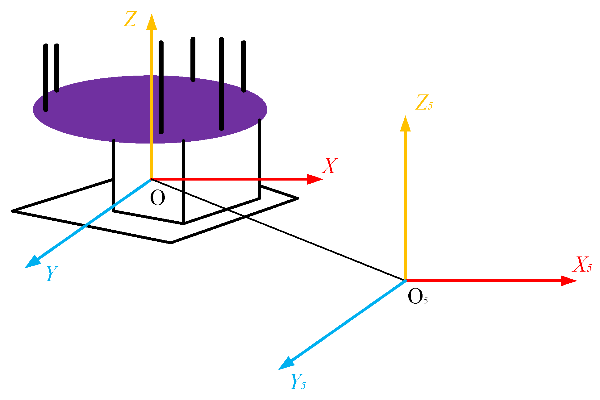
3.2.2. Displacement Error Analysis and Modeling of the Double-Deck Sliding Platform

A double-deck sliding platform and a converter mechanism comprise the active motion simulator. The double-deck sliding platform was built in a cross configuration, allowing for translational mobility on both the X and Y axes. The two degrees of freedom were independent of one another. As illustrated in Figure 4, when the docking mode was changed from vertical to horizontal, the primary motion simulator moved down the V-groove track in the X direction of the OXYZ coordinate system.
The movement along the X5 and Y5 axes in the O5X5Y5Z5 coordinate system was accomplished by the motor pulling the gear rotation to drive the pinion movement. The V-shaped wheel and the roller finished off the guiding limit. During motion, resistance and resistance torque were generated by the friction between the V wheel and the roller and the guide rail, as well as the system’s inertia.
The displacement errors along the X5 and Y5 axes of the double-deck sliding platform, as depicted in Figure 5, were caused primarily by transmission errors of the rack and pinion, deformations in the guide rail, and measurement errors of the grating ruler. The transmission faults of the rack and pinion were mostly caused by manufacture and installation problems, deformations in the gear teeth under the contact force experienced during meshing transmission, etc. Changes in the gap between the indicative grating and the scale grating caused by structural errors in the system, installation errors in the roller and lug, and friction and wear on the slide rails affected the precision of the grating ruler.
Here, the rotary motion was converted to linear motion by the rack and pinion drive mechanism; furthermore, the rack and sliding platform were fixed together, and the linear displacement of the rack along the meshing line was the displacement of the sliding platform along the corresponding coordinate axis. Therefore, the linear displacement of the rack in transmission was directly reflected in the displacement error of the sliding platform; given this, the rack displacement error model was:
Δ S = S S
where S and S’ indicate the theoretical and actual displacements of the gear when the gear rotated at an angle of θ1, respectively. Furthermore, rb represents the radius of the gear pitch circle, and DB and DH represent the elastic and contact deformation. The subscripts 1 and 2 were used to denote gears 1 and 2 quantities, respectively. We have:
Δ S = ( r b θ 1 D B 1 D H 1 + E 1 + E 2 D B 2 D H 2 ) r b θ 1 = ( E 1 + E 2 ) ( D B 1 + D H 1 + D B 2 + D H 2 )
where E1 and E2 represent the tooth profile error and tooth pitch error, respectively, of the gear and rack at the meshing point. Suppose that:
D B 1 + D H 1 + D B 2 + D H 2 = δ
and then Equation (5) can be expressed as:
Δ S = E δ
where E is the algebraic sum of E1 and E2, and δ is the sum of the deformation of meshing teeth along the meshing line and is the position function of meshing point.
The deformation of the contact surface between the slide rail and the roller was caused by the gravities of conversion mechanism, docking mechanism, upper slide rail, and their own impacting force experienced during the docking process. When the roller passes through the slide rail deformation surface, the force diagram is as shown in Figure 6. More specifically, given that Ft was the driving force of the direction of motion, G is the vertical force of the roller, and assuming that l was the instantaneous displacement of the indicative grating along the direction of motion, then β was the angle between the slide rail and the horizontal direction after deformation, i.e.,
β = 2 π l L
Here, L represents the range of the grating ruler; therefore, the measurement error of the grating ruler can be obtained as [46]:
e β = Δ l = [ F t g G + g sin ( 2 π l L ) cos ( 2 π l L ) μ g cos 2 ( 2 π l L ) ] × v ¯
where V ¯ is the motion velocity of the grating ruler.
Figure 6 illustrated the force diagram of the slide rail deformation surface, i.e., when the roller passed through this surface.
Furthermore, the displacement error model along the respective displacement direction of the double-deck slide rail was then obtained by integrating Equations (7)–(9) to yield:
Δ ( m o v ) = ( E + δ ) + [ F t g G + g sin ( 2 π l L ) cos ( 2 π l L ) μ g cos 2 ( 2 π l L ) ] × v ¯

4. Dynamic Analysis of the Docking Process

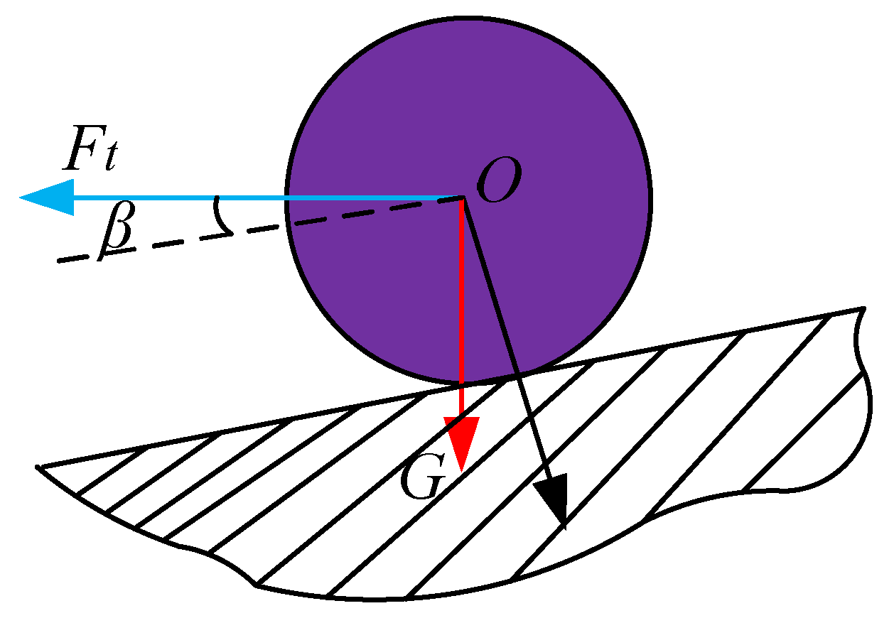
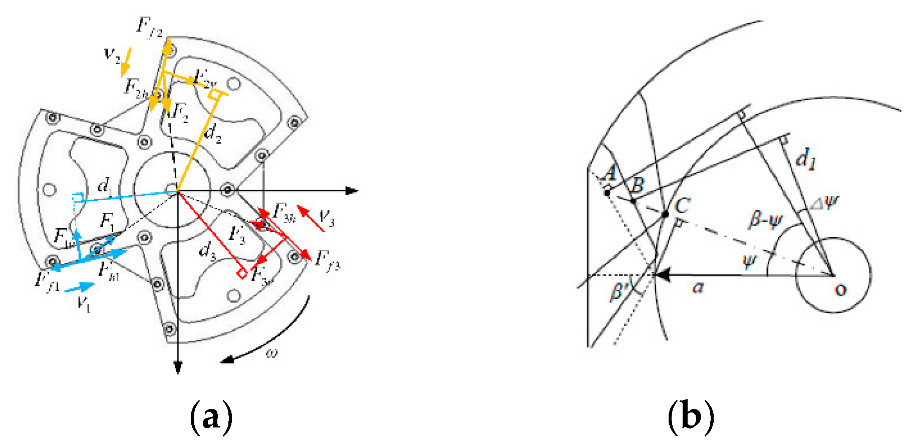
4.1. Contact Impact Analysis of the Docking Process

4.1.1. Modeling Contact Torque

During the docking process, attitude correction of the passive docking mechanism was implemented with the contact force and torque exerted by the locking jaw of the active docking mechanism. Therefore, it was necessary to analyze the force and torque exerted on the passive docking mechanism during the docking process.
When attitude errors existed between the active and passive docking mechanisms, the locking jaw was first contacted with the V-shaped groove surface of the passive docking mechanism in the docking process, as illustrated in Figure 7.
As shown in Figure 7a, during the docking process, there was a certain angular deviation between the active and passive motion simulators and the origin coordinate system. The hook claw completed the hugging action and adjusted the attitude deviation under the action of the three V-shaped guide grooves, and finally reached the bottom of the V-groove to complete the docking operation. In this analysis, the collision types were divided into two cases: (1) when there was a y-direction yaw angle, it was positioned as a positive collision; (2) when there was a roll angle or pitch angle, it was defined as an oblique collision. In Figure 7, F1, F2, and F3 represented the contact force exerted on the side contact point of the V-shaped groove by the three locking jaws; given this, the attitude of the passive docking mechanism was continuously changed and adjusted as the locking jaw closed in response to the contact force. Here, the trajectory of the contact point between the top of the locking jaw and the V-shaped groove surface forms an arc on the groove surface. The contact impacting force of each locking jaw can therefore be decomposed into the circumferential force perpendicular to the groove surface, the force directed toward the groove center along the groove surface, and the force directed toward the bottom surface along the groove surface.
Given that A was the initial contact point and C was the contact point between the locking jaw and the V-shaped groove when the docking was completed, then trajectory AC was the displacement vector of the jaw during the entire docking process. When the docking mechanism rotated at an angle of Δψ around the z-axis in response to the contact force, there were
M Z = i = 1 3 F i v d i in   the   formula d i = ( l O A i v O t ) cos ( β ψ + Δ ψ ) l O A i = a sin ψ tan ( β ψ ) + a cos ψ F i v = F i sin ( β ψ + Δ ψ )
Here, Mz is the rotational torque applied on the z-axis; Fiv is the rotational force; di is the torque. As can be seen from Equation (11), when the hook moves to the position B shown in Figure 7b, the calculation of the contact force was determined by the equivalent stiffness and damping characteristics, and the hook moment was obtained. The calculation of the impact force below provided the basis.
Note that the same method can be used to determine expressions for Mx and My, which represented the rotational torques that the x- and y-axes of the passive docking mechanism exert in response to the locking jaw during the docking process.

4.1.2. Modeling Impacting Force

When an impact occurs, the contact or impacting force caused a deformation at the contact point. If δv describes the intrusive deformation between the locking jaw and the V-shaped groove surface and the matching surface of the passive docking mechanism along the normal line direction of the contact point, considering that the loss of energy in the impact is caused by the damping of material, according to Herts theory, the impacting force model is [47]:
F v = K v δ v n v + C v δ ˙ v n v
K v = 4 E 1 E 2 r 1 r 2 3 [ E 2 ( 1 μ 1 2 ) + E 1 ( 1 μ 2 2 ) ] r 1 + r 2
where E1 and E2 represent the elastic modulus of the two colliding objects, μ1 and μ2 represent Poisson’s ratio of materials, and r1 and r2 are the radii of the contact points.

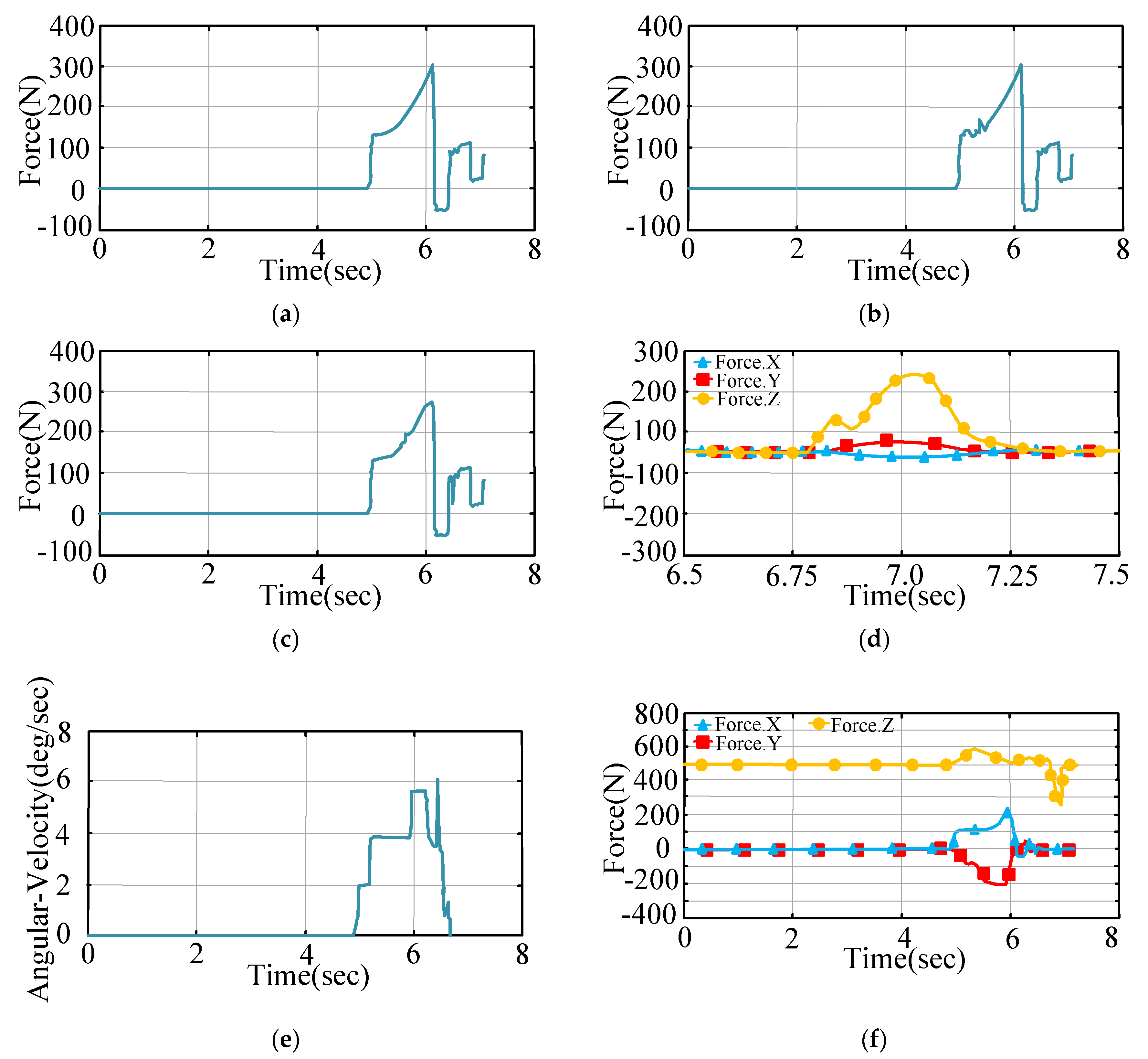
4.2. Dynamic Model and Simulation Analysis of the Docking Process

The active and passive docking mechanisms are respectively installed on the active and passive motion simulator through the flange and supporting rod. Here, the passive motion simulator is the follow-up system of the passive docking mechanism during the docking process. Furthermore, the rotation and displacement are generated with the change in attitude of the passive docking mechanism in response to the contact force of the locking jaw.
During the docking process, the rotational motion of the mandrel balance assembly, spherical joint, and the end-effector take the spherical center O2 as the center of rotation. Therefore, the rotation equation of the rolling system is
M O 2 = M S M Z M P
T 2 = 1 2 A P 2 + 1 2 B r 2 + 1 2 H q 2
Here, P, r, and q represent the velocities of spherical joint turns around the X2, Y2, and Z2 axes, respectively.
In addition, the Nissen equations corresponding to components of the spherical joint angle are
{ T 2 ψ ˙ 2 T 2 ψ = M ψ T 2 θ ˙ 2 T 2 θ = M θ T 2 φ ˙ 2 T 2 φ = M φ
where Mψ, Mθ, and Mφ are the components of M O 2 for each coordinate axis, respectively.
The dynamic differential equation of the rotational motion of the spherical joint during the docking process is
{ ( A sin 2 θ + J Z + J P ) ψ ¨ = ( H 2 A sin θ ) ψ ˙ θ ˙ cos θ + H φ ˙ θ ˙ sin θ + M ψ M φ cos θ A θ ¨ = ( A H ) ψ ˙ 2 sin θ cos θ H φ ˙ ψ ˙ sin θ + M θ A H φ ¨ sin 2 θ = ψ ˙ θ ˙ ( A H sin θ + A H sin θ cos 2 θ H 2 cos 2 θ ) H 2 φ ˙ θ ˙ sin θ cos θ + ( A sin 2 θ + B cos 2 θ ) M φ H M ψ cos θ
Equation (17) was obtained by Nielsen transformation of Equation (15), where JZ, JP are the rotational inertia of spherical joint and the end-effector, respectively. From Formula (17), it can be known that the above equations described the dynamic characteristics of the rolling device during the docking process, which consisted of a spherical joint, a mandrel balancing assembly, and an end-effector.
Here, the effect of the impact on the test platform was analyzed by combining with the dynamic simulation software. The effect of the impacting force on the test platform during the docking process was reflected in the change in performance of specific components in response to the impacting force. These components include the spherical joint, the mandrel, and so on. We conducted a co-simulation of the test platform and the docking mechanism by using ADAMS, a dynamic analysis software system.
Simulate the real material properties on the simulation material property settings. Ask the partner to learn that high-strength lightweight materials such as aluminum alloy and titanium alloy are used, and set their properties as material properties in the simulation.
Through the simulation, we obtained the variation of the impacting force generated during the docking process as a reference for further analysis of related components.
According to the theorem of impulse, when an impact occurs, the impacting force can be expressed as
F I = m v t
where m is the mass of moving objects, v is the relative velocity, and t is the impacting time. Here, the impacting velocity and time both depend on the initial conditions of the docking and the retracting speed of the locking jaw. Under the vertical docking mode, the mass of the moving object is the equivalent mass of the passive motion simulator and the passive docking mechanism, but in the horizontal docking mode, the mass of moving object is only the mass of the passive docking mechanism. Hence, when the initial conditions and the retracting speed of the locking jaw are the same, the impacting force generated by vertical docking is larger, and the effect on the related components is larger. Therefore, we need only perform an analysis of impacts during the docking process in vertical docking mode. In this paper, a set of initial limit conditions are taken for co-simulation in the two docking cases of frontal impact and oblique impact, respectively. The initial conditions are shown in Table 1.
The mass and inertia characteristics of each part of the motion simulator and the docking mechanism are shown in Table 2. The data in the table are obtained from previous theoretical research and experiments [48].
The movement of the locking jaw of the active docking mechanism is realized by controlling the lifting speed of the screw-thread lifting platform. Here, the three locking jaws abide by the same law of motion. In order to make the boundary conditions closer to the follow-up experiments and the required design indicators, the speed of the upper and lower thread lifting platforms is defined as 0.01 m/s. The corresponding number of change curves under the two initial docking conditions are obtained through simulation, as shown in Figure 8 and Figure 9.
It can be seen from Figure 8a–f that the force trend of the three locking claws is almost the same. It can be seen that the three locking claws receive almost the same force at the same time. Impact force indicates that the three pawls were stable after impact for an impact from the front. It can be seen from Figure 8d that, when the platform is hit by the frontal impact, the force from the impact direction, which was the Z direction, is relatively large, which is in line with the force situation at the time of design. Although there are forces in the Y and Z directions, the force amplitude difference was not big, since the X and Y directions are on the same horizontal plane, when the spherical pair is subjected to a force in one direction, due to the action of the structure, it is bound to produce a resultant force of the same size and opposite direction, so that the whole docking mechanism can achieve balance in the horizontal direction, without overturning or horizontal translation. This indicates that the designed structure will not be subjected to too much force in individual directions to cause attitude deviation after being hit.
It can be seen from Figure 9a–c that, conversely, when an oblique impact occurs, the contact time and the contact impacting force between the three locking jaws and the V-shaped groove sides during the docking process differ, which may cause disturbances in the test platform during the docking process, as it is prone to vibration. Furthermore, the angular velocity of the spherical joint is larger than that of the frontal impact, as is each component of force; components of the impacting force between the passive docking mechanism and the upper matching surface of the active part are large, thus showing that the impacting force of an oblique impact is larger than that of a frontal impact. Here, the maximum impacting force is 280 N, which will impact the spherical joint assembly. The above analysis results provide a theoretical basis for further structure optimization.

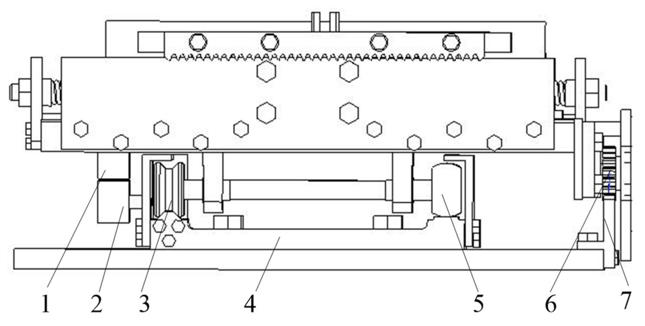
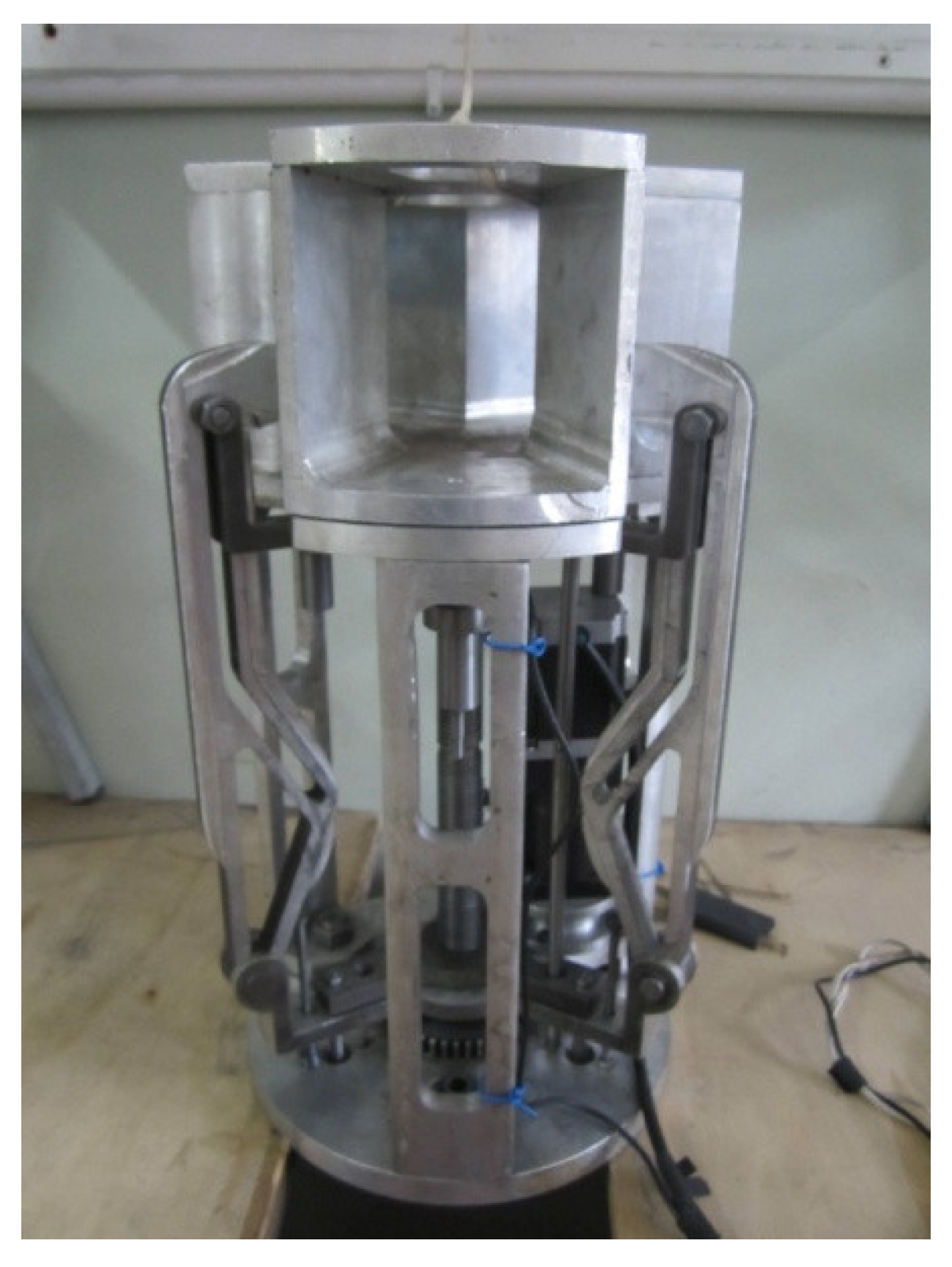
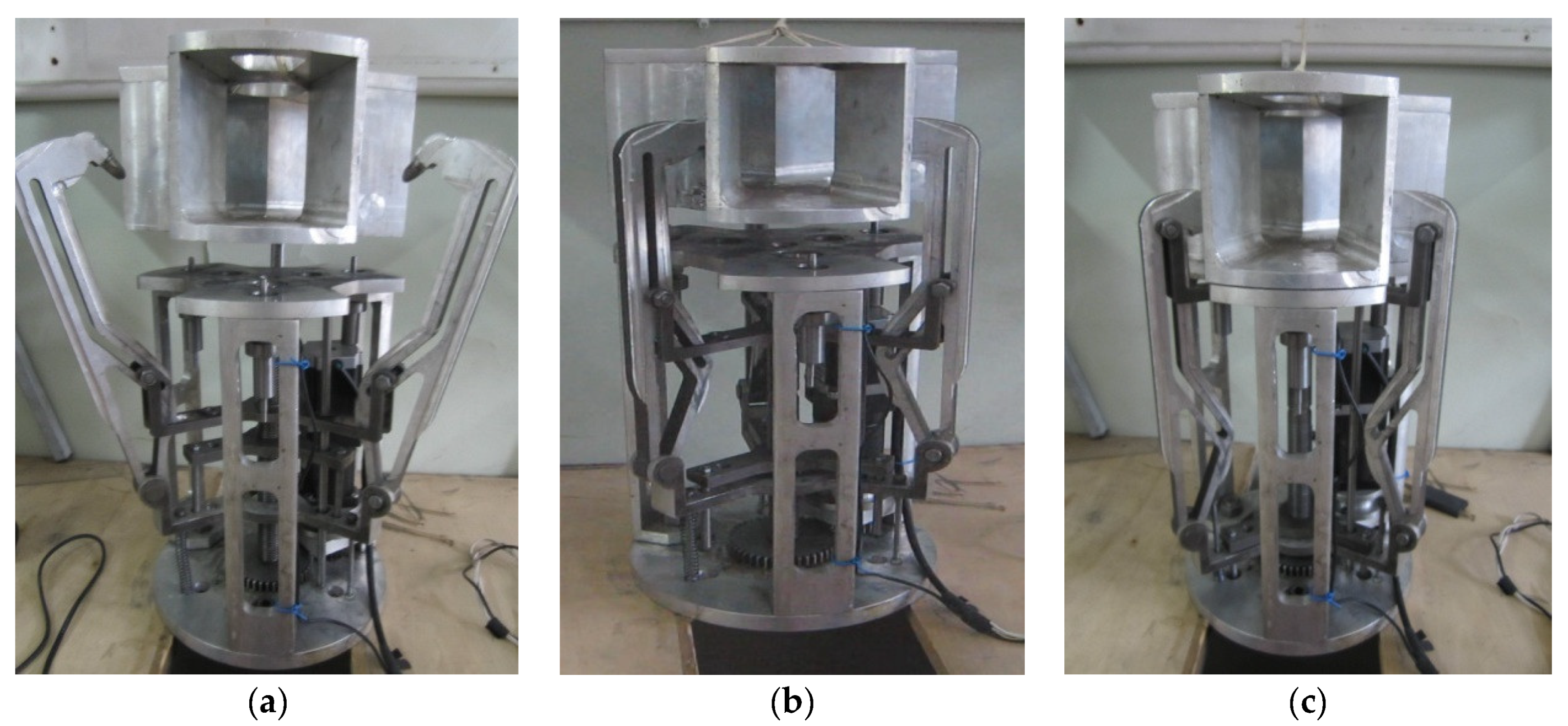
5. Testing Method and Experimental Research on Physical Prototype of the Docking Mechanism

According to the above virtual design results, the production drawings of all parts are designed, and then the physical prototype is produced and assembled, as shown in Figure 10. According to the lightweight requirements of the prototype, the main structure is made of high-strength lightweight materials such as aluminum alloy and titanium alloy; according to the control requirements of the hook and claw, the prototype is equipped with a driver and controller to control the implementation of the hook and claw retraction action and speed parameter adjustment; according to the pressure monitoring and feedback requirements, the junction surface of the prototype is reserved and equipped with pressure sensors, which can feed back the monitored pressure parameters in real time.
The docking process of the active docking mechanism is shown in Figure 11. At the beginning of the docking, the opening radian of the hook claw is the largest. Then, guide grooves of the two locking claws are gradually closed and adjusted to correct the position deviation. Then, the passive mechanism is pulled in and locked to eliminate the attitude rotation deviation of each degree of freedom, and the motion test is completed.
The experiment is conducted according to the physical prototype test method described above, and the coaxial forward impact butt joint test is shown in Figure 12. During the test, in order to simulate the weightlessness, the gravity value of the passive mechanism is offset by adjusting the counterweight size of the lifting mechanism. At this time, the feedback value read from the sensor is the pressure value at the time of docking (the influence of gravity on the pressure at the junction surface has been ignored).
Since the theoretical value unit of the pressure feedback value is kg, in order to maintain data consistency, the reading instrument unit of the pressure sensor is adjusted to kg. The docking time and maximum grasping force of the three groups of different initial states read by the test are shown in Table 3.
Then, according to the mechanical property testing and calculation method described above, the average value of each group of data is taken as the maximum grasping force, and the maximum grasping force value is 11.12 kg. It basically corresponds to the simulation results, which verifies the rationality of the theory and simulation of the docking process.

6. Discussion

Corresponding research was carried out on the new docking mechanism and the simulation test bench for degrees of freedom. Although some research results have been achieved, there were still many issues to be further studied and explored:
  • The buffer mechanics test of the docking mechanism needs to be improved. In order to more effectively ensure the reliability of the docking mechanism, it is necessary to deeply analyze the dynamic characteristics of the buffering process to further verify the correctness of the established attitude kinematics and dynamic models; at the same time, the collision angle only considers the frontal and oblique collisions, and does not consider whether the collision in space, that is, the collision of the three axes of XYZ with a certain inclination angle will affect the stability of the entire mechanism;
  • At present, only the static analysis of the hook claw is carried out, and the dynamic analysis should be carried out in the follow-up work to fully reflect the transient deformation under force. In the low temperature of space and the change of the material in the vacuum environment, the change of the material should also be considered, and the structure will not be affected. It will cause embrittlement or even breakage due to ultra-low temperature. Should the flexible grasping robot hand be taken into consideration?
  • The research on the joint simulation experiment method in the simulated space vacuum environment still needs to be explored. The fact that no one is now operating the docking, signal transmission, whether the space robot will cause attitude deviation due to delay after receiving the signal, and how to correct the deviation are all connected. These are future things to consider.

7. Conclusions

On the base of functional requirements, in this paper, we propose a joint test configuration platform for implementing both vertical and horizontal docking. The coordinate system of the docking system is established, and the kinematics analysis of the composite docking test is carried out. At the same time, the influences of system random errors on the attitude accuracy of the motion simulator are also analyzed. Combined with the working characteristics of the three-jaw docking mechanism, we also analyzed contact impacts for both the active and passive docking mechanisms. Furthermore, we established the contact impacting force and torque models, and simulated the dynamic characteristics of our composite docking test platform during the docking process. Our analysis shows that the impacting force between the docking mechanisms is greater in the vertical docking mode. Therefore, we selected a set of initial conditions for both the frontal and oblique impact conditions, and then performed co-simulations via ADAMS. Through these simulations, we obtained the curves of the impacting force between the docking mechanisms, the angular velocity curve of the spherical joint, and the force curve under the two initial conditions during the docking process. These provide a theoretical reference for analyzing the reliability of key components.

Author Contributions

Methodology, Y.Z.; Project administration, J.S.; Validation, E.Z.; Writing—review & editing, J.Z. All authors have read and agreed to the published version of the manuscript.

Funding

The work was financially supported by the National Natural Science Foundation of China (51375125).

Institutional Review Board Statement

Not applicable.

Informed Consent Statement

Not applicable.

Data Availability Statement

Not applicable.

Conflicts of Interest

The authors declare no conflict of interest.

References

  1. Sun, L.; Jiang, J.J. Saturated adaptive relative motion coordination of docking ports in space close-range rendezvous. IEEE Trans. Aero. Elec. Syst. 2020, 6, 4889–4898. [Google Scholar] [CrossRef]
  2. Murtazin, R.; Sevastiyanov, N.; Chudinov, N. Fast rendezvous profile evolution: From ISS to lunar station. Acta Astronaut. 2020, 173, 139–144. [Google Scholar] [CrossRef]
  3. Wei, Z.T.; We, H.; Hu, H.Y.; Jin, D.P. Ground experiment on rendezvous and docking with a spinning target using multistage control strategy. Aerosp. Sci. Technol. 2020, 104, 105967. [Google Scholar] [CrossRef]
  4. Walter, F.T.; Michael, G.H.; James, L. Autonomous and autonomic systems: A para-digm for future space exploration missions. IEEE Trans. Syst. Cybern. Part C Appl. Rev. 2006, 3, 279–291. [Google Scholar]
  5. Boesso, A.; Francesconi, A. ARCADE small-scale docking mechanism for micro-satellites. Acta Astronaut. 2013, 86, 77–87. [Google Scholar] [CrossRef]
  6. Branz, F.; Olivieri, L.; Sansone, F.; Francesconi, A. Miniature docking mechanism for CubeSats. Acta Astronaut. 2020, 176, 510–519. [Google Scholar] [CrossRef]
  7. Xu, Y.; Shao, X. Design of cone rod docking mechanism for intelligent micro nano satellite station. Shanghai Aerosp. 2009, 1, 43–47. [Google Scholar] [CrossRef]
  8. Jiang, S.; Yan, X. Virtual prototyping technology and its application prospect in China. Machinery 2003, 30, 4–9. [Google Scholar]
  9. Shen, C.; Liu, X.; Sheng, L. Research progress and development trend of virtual prototyping technology. Res. Agric. Mech. 2008, 234–236. [Google Scholar]
  10. Schweiger, M. Space Flight Simulator 2006 Edition User Manual. 2006. Available online: http://orbit.medphys.ucl.ac.uk/download/Orbiter.pdf (accessed on 25 August 2010).
  11. Philip, N.K.; Thasyanam, M.R. Relative position and attitude estimation and control schemes for the final phase of an autonomous docking mission of spacecraft. Acta Astronaut. 2003, 52, 511–522. [Google Scholar] [CrossRef]
  12. Ma, Y. Dynamic simulation of virtual prototype of spacecraft deployment mechanism. Chin. Acad. Sci. 2006, 25–32. [Google Scholar]
  13. Lu, Q.C.; Shao, X.W.; Duan, D.P. Design of collision triggered non cooperative target docking capture mechanism. Shanghai Aerosp. 2013, 30, 7–12. [Google Scholar]
  14. Yu, W.; Wang, W. Design and analysis of grasping docking mechanism. Robot 2010, 32, 233–240. [Google Scholar] [CrossRef]
  15. Lai, Y.; Zhao, M. Research on Key Technologies of Ground Six Degree of Freedom Test Bench for Small Satellite Docking Mechanism; Harbin University of Technology: Harbin, China, 2011; pp. 10–11. [Google Scholar]
  16. Zhang, C. Parameter calculation of spring buffer limiter in photoelectric tracking equipment. J. Chang. Univ. Technol. 2012, 35, 31–32. [Google Scholar]
  17. Xie, W.; Cai, Y.; Li, Y. Research on standardized design criteria for module interface of on orbit service spacecraft. Aerosp. Control. 2010, 28, 49–52. [Google Scholar]
  18. Zhang, Y. On orbit replaceable module mechanism and structure design of spacecraft. Shenyang J. Aeronaut. Astronaut. 2014, 311, 72–76. [Google Scholar]
  19. Richards, M.G.; Springmann, P.N.; Mcvey, M.E. Assessing the Challenges to a Geosynchronous Space Tug System. In Proceedings of the Conference on Modeling, Simulation, and Verification of Space-based System II, Orlando, FL, USA, 31 March 2005; Massachusetts Institute of Technology: Cambridge, MA, USA, 2010. [Google Scholar]
  20. Khullar, S. Siddharth Khullar—Massachusetts Institute of Technology. Available online: www.siddharthkhullar.net (accessed on 12 June 2013).
  21. Zhang, C. Spacecraft space docking mechanism technology. Chin. Sci. 2014, 44, 20–26. [Google Scholar] [CrossRef]
  22. Zhou, J. Manned space rendezvous and docking technology. Manned Space 2011, 6, 1–4. [Google Scholar]
  23. Zhu, R. Comparative study on Chinese and foreign rendezvous and docking technology. Spacecr. Eng. 2013, 22, 8–15. [Google Scholar]
  24. Du, H. Research on the design of large tolerance space cooperative target acquisition and docking device. Mech. Des. Manuf. 2013, 2, 12–15. [Google Scholar]
  25. Ding, H.; Hu, J.; Lin, J.; Jiang, W.; Zhang, H.; Wang, D. Research on modal characteristics of torque measuring device, a key component of space docking mechanism. J. China Univ. Metrol. 2022, 33, 7–14. [Google Scholar]
  26. Chen, C.; Wang, J.; Chen, J.; Cui, J.; Huo, W.; Jiang, A. Analysis of transfer power of space weak impact docking mechanism. Mech. Electron. 2020, 38, 3–8. [Google Scholar]
  27. Lin, Q. Research on space rendezvous and docking simulation technology. J. Equip. Command. Technol. Coll. 2008, 19, 53–57. [Google Scholar]
  28. Fehse, W. Automated Rendezvous and Docking of Spacecraft; Cambridge University Press: Cambridge, UK, 2003; pp. 40–41. [Google Scholar]
  29. Motaghedi, P. On-Orbit Performance of the Orbital Express Capture System; SPIE69580E; Society of Photo-Optical Instrumentation Engineers: Albuquerque, NM, USA, 2008. [Google Scholar]
  30. Rodgers, L.P. Concepts and Technology Development forthe Autonomous Assembly and Reconfiguration of Modular Space Systems; Massachusetts Institute of Technology: Cambridge, MA, USA, 2006. [Google Scholar]
  31. Adam, L.G.; Lynda, R.E.; James, A.E. Space Shuttle Orbiter Structures & Mechanisms. In Proceedings of the AIAA SPACE 2011 Conference & Exposition, Long Beach, CA, USA, 27–29 September 2011; pp. 3–22. [Google Scholar]
  32. Evans, J.W. Autonomous Rendezvous Guidance and Navigation for Orbital Express and Beyond. In Proceedings of the 16th AAS/AIAA Space Flight Mechanics Conference; AAS Publications Office: Tampa, FL, USA, 2006. [Google Scholar]
  33. Nilson, T.; Christiansen, S. Docking system for autonomous, un-manned docking operations. In Proceedings of the 2008 IEEE Aerospace Conference, Big Sky, MT, USA, 1–8 March 2008; pp. 2770–2783. [Google Scholar]
  34. ESA. 50 Science Mission Proposals. 2007. Available online: http://www.esa.int (accessed on 16 October 2022).
  35. Geng, Y. Gaze Observation Mission Planning and Optimal Attitude Control of Agile Spacecraft; Harbin Institute of Technology: Harbin, China, 2021. [Google Scholar] [CrossRef]
  36. Li, X. Research on Spacecraft Orbit Configuration and Autonomous Rendezvous and Docking Control Method; Harbin Institute of Technology: Harbin, China, 2018. [Google Scholar]
  37. Wang, M. Research on Attitude Control of Space Robot after Target Capture; Northwest University of Technology: Xi’an, China, 2015. [Google Scholar]
  38. Huang, C.; Chen, X.; Wang, Y. Rendezvous and docking simulation and attitude tracking control based on air bearing platform. Chin. J. Inert. Technol. 2015, 23, 831–836. [Google Scholar]
  39. Qu, Z.; Ye, Z. Research on error modeling of 9-DOF motion system. In Proceedings of the 2011 2nd Asia-Pacific Conference on Wearable Computing Systems (APWCS 2011 V6), Changsha, China, 19 March 2011; pp. 121–124. [Google Scholar]
  40. Lu, S. Influence of Forming Process on Impact Characteristics of Composite Strength S-Shaped Structural Parts; Dalian University of Technology: Dalian, Chian, 2014. [Google Scholar]
  41. Gao, Q.; Huang, X. Modeling and Simulation of collision characteristics of multistage cylinder erecting system. In Proceedings of the 2003 National Annual Conference on System Simulation, Washington, DC, USA, 30 March–2 April 2003; pp. 668–672. [Google Scholar]
  42. Mahesh, V.; Mahesh, V. Ballistic characterization of fiber elastomer metal laminate composites and effect of positioning of fiber reinforced elastomer. Proc. Inst. Mech. Eng. Part L J. Mater. Des. Appl. 2022, 236, 663–673. [Google Scholar] [CrossRef]
  43. Rajkumar, D. A Novel Flexible Green Composite with Sisal and Natural Rubber: Investigation under Low-Velocity Impact. J. Nat. Fibers 2022, 10, 1–12. [Google Scholar] [CrossRef]
  44. Mahesh, V. Comparative study on ballistic impact response of neat fabric, compliant, hybrid compliant and stiff composite. Thin-Walled Struct. 2021, 165, 107986. [Google Scholar] [CrossRef]
  45. Zhang, Y.; Wang, J.; Song, Y.; Snn, L. Dynamic simulation analysis for docking mechanism of on-orbit-servicing satellite. Appl. Mech. Mater. 2014, 487, 313–318. [Google Scholar] [CrossRef]
  46. Zhang, Y.; Wang, Y.; Song, Y.; Zhou, L. Kinematics analysis and simulation of small satellite docking mechanism end executor. Appl. Mech. Mater. 2014, 487, 460–464. [Google Scholar] [CrossRef]
  47. Zhang, Y.; Sun, L.; Hu, N.; Wang, J. Dynamic analysis of small satellite vertical docking test platform. J. Harbin Univ. Sci. Technol. 2014, 19, 6–11. [Google Scholar]
  48. Zhang, Y.; Sun, L.; Lai, Y.; Dai, Y. Dynamics and Attitude Error Analysis for Dock Test System of Small Satellite. Trans. Nanjing Univ. Aeronaut. Astronaut. 2015, 32, 372–379. [Google Scholar]
Figure 1. Joint assembly diagrams of the composite docking test platform, (a) vertical docking; (b) horizontal docking.
Applsci 12 12093 g001
Figure 2. The space docking coordinate system.
Applsci 12 12093 g002
Figure 3. Attitude transformation of the passive docking mechanism establishing coordinate system oxyz. 2. Space Space docking coordinate system.
Applsci 12 12093 g003
Figure 4. Attitude transformation of the active motion simulator.
Applsci 12 12093 g004
Figure 5. Structure of the double-deck sliding platform. 1. Indicative grating, 2. Scale grating, 3. V-type wheel, 4. Slide rail seat, 5. Roller, 6. Rack, 7. Pinion.
Applsci 12 12093 g005
Figure 6. Force diagram of the slide rail deformation surface.
Applsci 12 12093 g006
Figure 7. Illustrating the contact force between the active and passive docking mechanisms (a) analysis of forces; (b) trajectory of locking jaw.
Applsci 12 12093 g007
Figure 8. Curves of corresponding quantities under the frontal impact (d) for locking jaw 1 (a) for locking jaw 2 (b) for locking jaw 3 (c) between the passive docking mechanism and the matching surface (e) showing the angular velocity of the spherical joint (f) spherical joint.
Applsci 12 12093 g008
Figure 9. Curves of corresponding quantities under the oblique impact (a) for locking jaw 1; (b) for locking jaw 2; (c) for locking jaw 3 (d) between the passive docking mechanism and the matching surface; (e) showing the angular velocity of the spherical joint; (f) spherical joint.
Applsci 12 12093 g009
Figure 10. Docking mechanism prototype.
Applsci 12 12093 g010
Figure 11. Vertical docking test, (a) initial phase of docking; (b) claw retraction and drawing in stage; (c) docking completed.
Applsci 12 12093 g011
Figure 12. Vertical docking test (a) test with offset of 40 mm; (b) test with offset of 30 mm; (c) test with offset of 20 mm.
Applsci 12 12093 g012
Table 1. Initial condition of attitudes.
X/mmY/mmZ/mmψθφ
Frontal Impact0050500
Oblique Impact404050555
Table 2. Characteristic parameters of mass and inertia.
m (Kg)Ix (Kg∙m2)Iy (Kg∙m2)Iz (Kg∙m2)
Active Docking Mechanism12.90.6240.8270.827
Passive Docking Mechanism20.1980.1980.285
Mandrel Balancing Assembly252.252.255.635
End-Effector21.21.961.964.79
Rotating Hanger18.5003.95
Table 3. Four groups of contact force and buffering force.
Measured ValueTest Group
Offset 20 (mm)Offset 30 (mm)Offset 40 (mm)
Time (s)120122125
Catching Force (kg)11.9410.0811.33
Publisher’s Note: MDPI stays neutral with regard to jurisdictional claims in published maps and institutional affiliations.

