
A Theoretical Model of Roof Self-Stability in Solid Backfilling Mining and Its Engineering Verification

 ,
,  ,
,
Abstract
:1. Introduction
2. Roof Structure and Roof Self-Stability Concept in Backfilling Mining
2.1. Roof Structure Characteristic
2.2. Roof Self-Stability Concept and Characteristic
3. Construction of Roof Self-Stability Model in Backfilling Mining
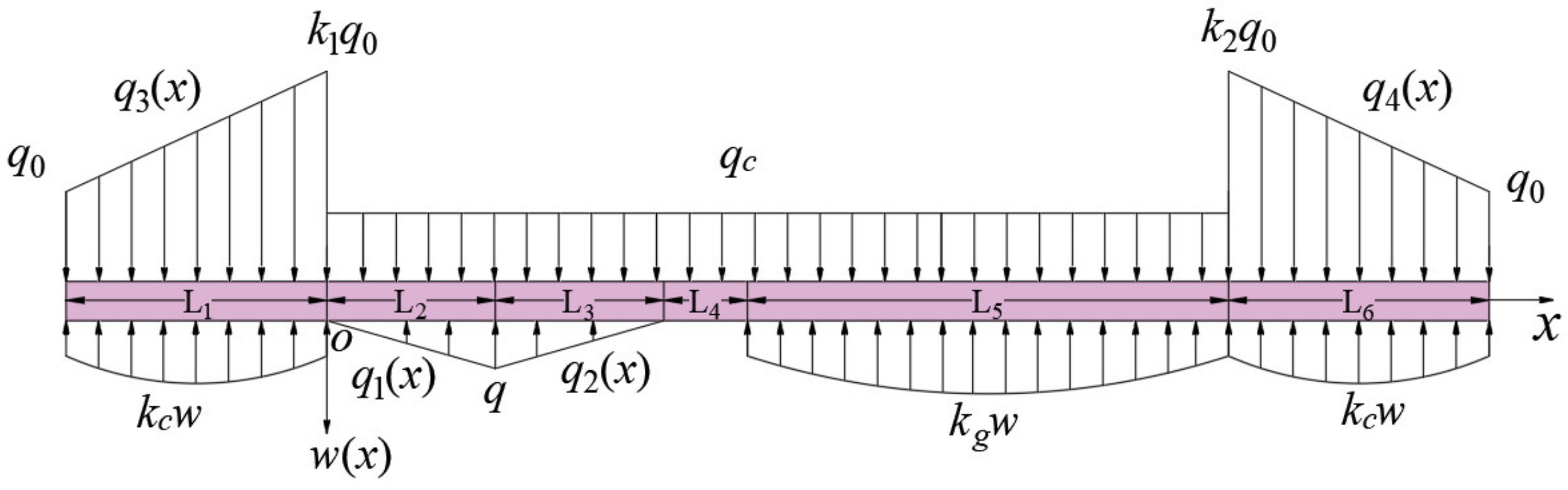
3.1. Self-Stability Model of Strike Roof
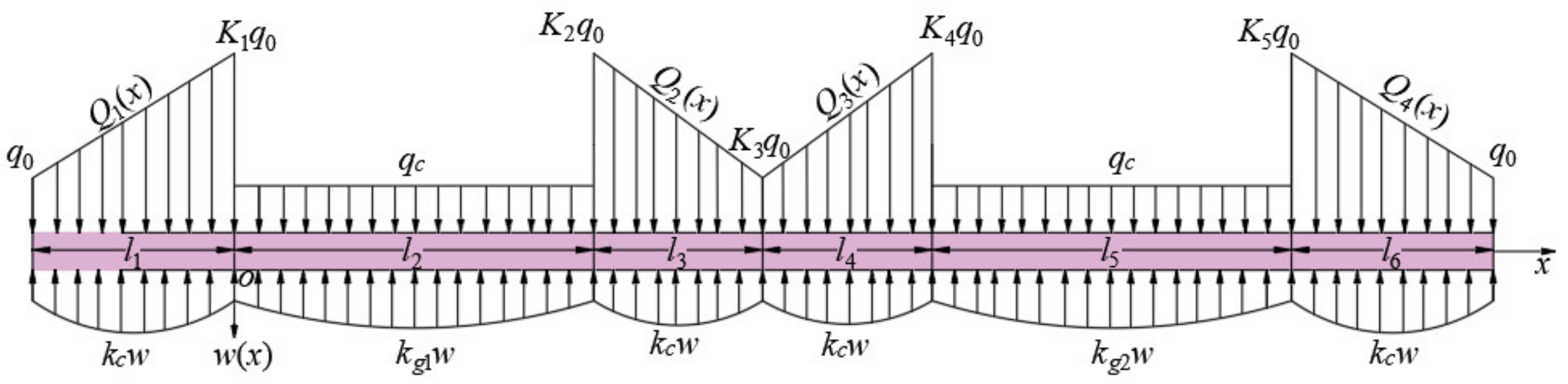
3.2. Dip Roof Self-Stability Model
4. Effect Analysis of Roof Self-Stability Factors
4.1. Effect Analysis of Roof Self-Stability Factors along Strike
- (1)
- Preliminary setting of parameters
- (2)
- Effect analysis of elastic foundation coefficient of backfill
- (3)
- Effect analysis of supporting-peak loads
- (4)
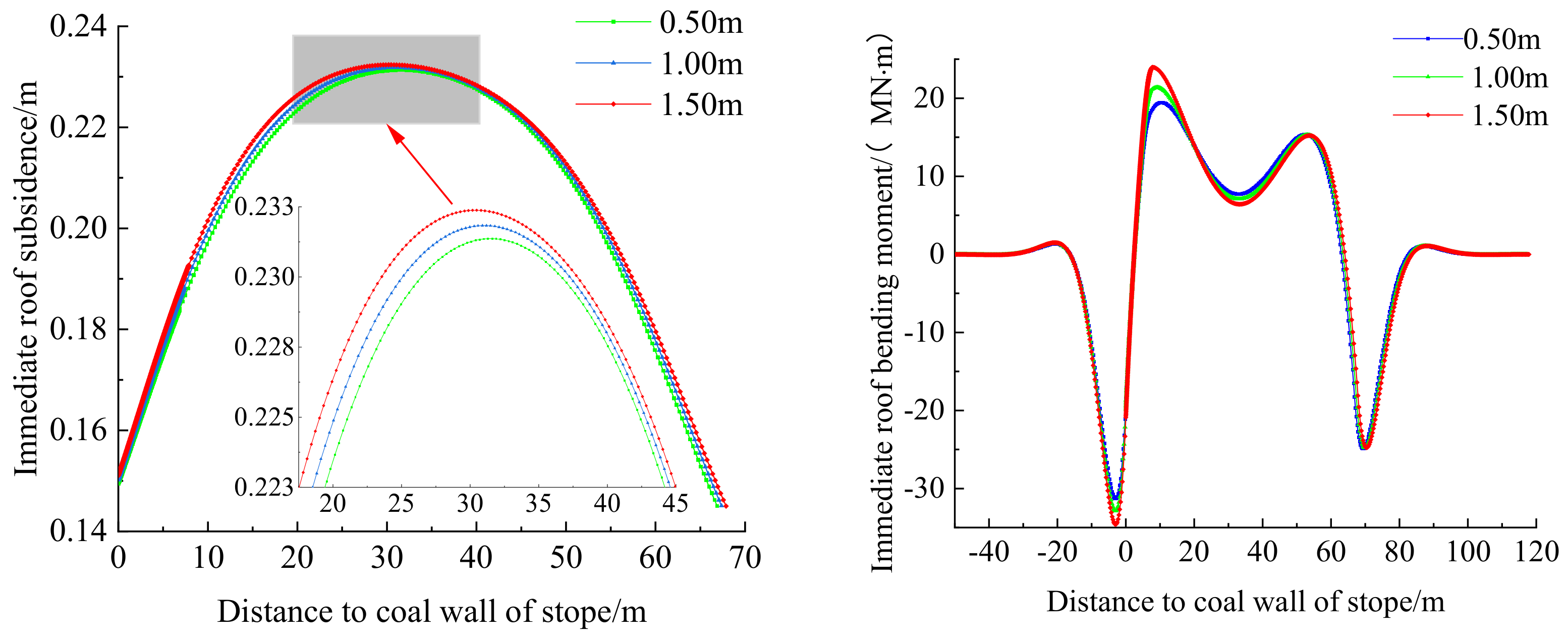
- Effect analysis of unsupported-roof distances
- (5)
- Effect analysis of advancing distance of working face
4.2. Effect Analysis of Roof Self-Stability Factors along Dip
- (1)
- Preliminary setting of parameters
- (2)
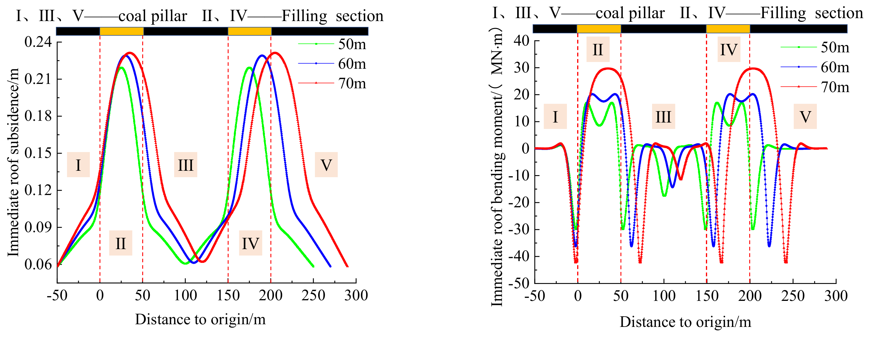
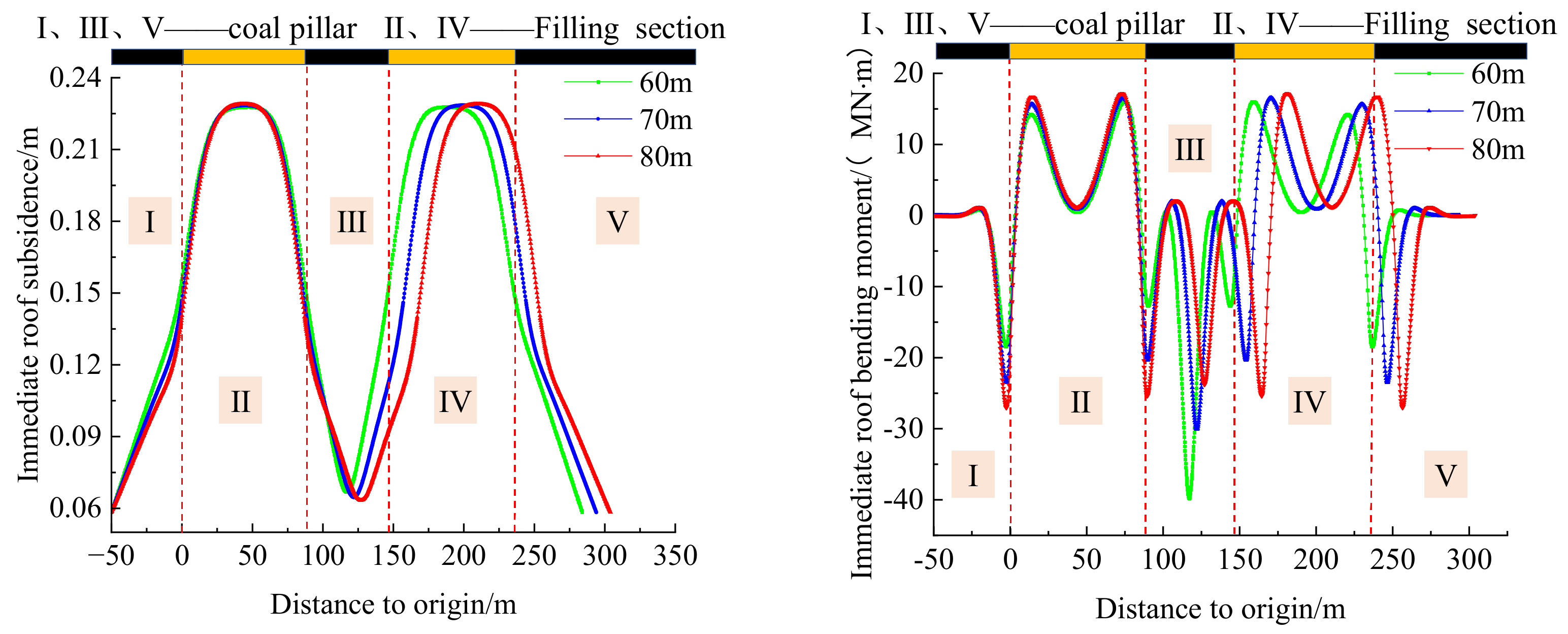
- Effect analysis of working face size
- (3)
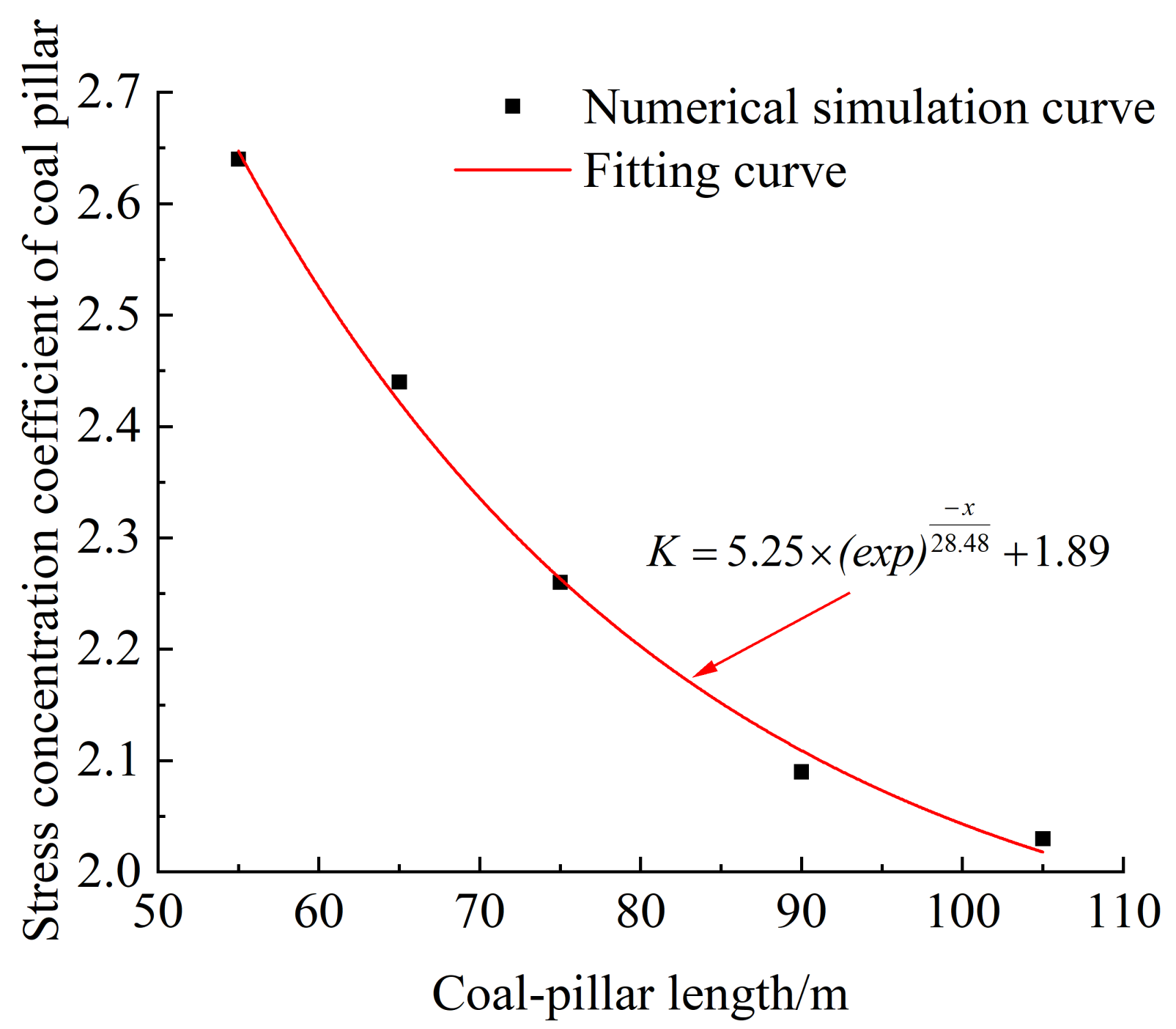
- Effect analysis of section coal-pillar size
5. Engineering Control Method for Roof Self-Stability
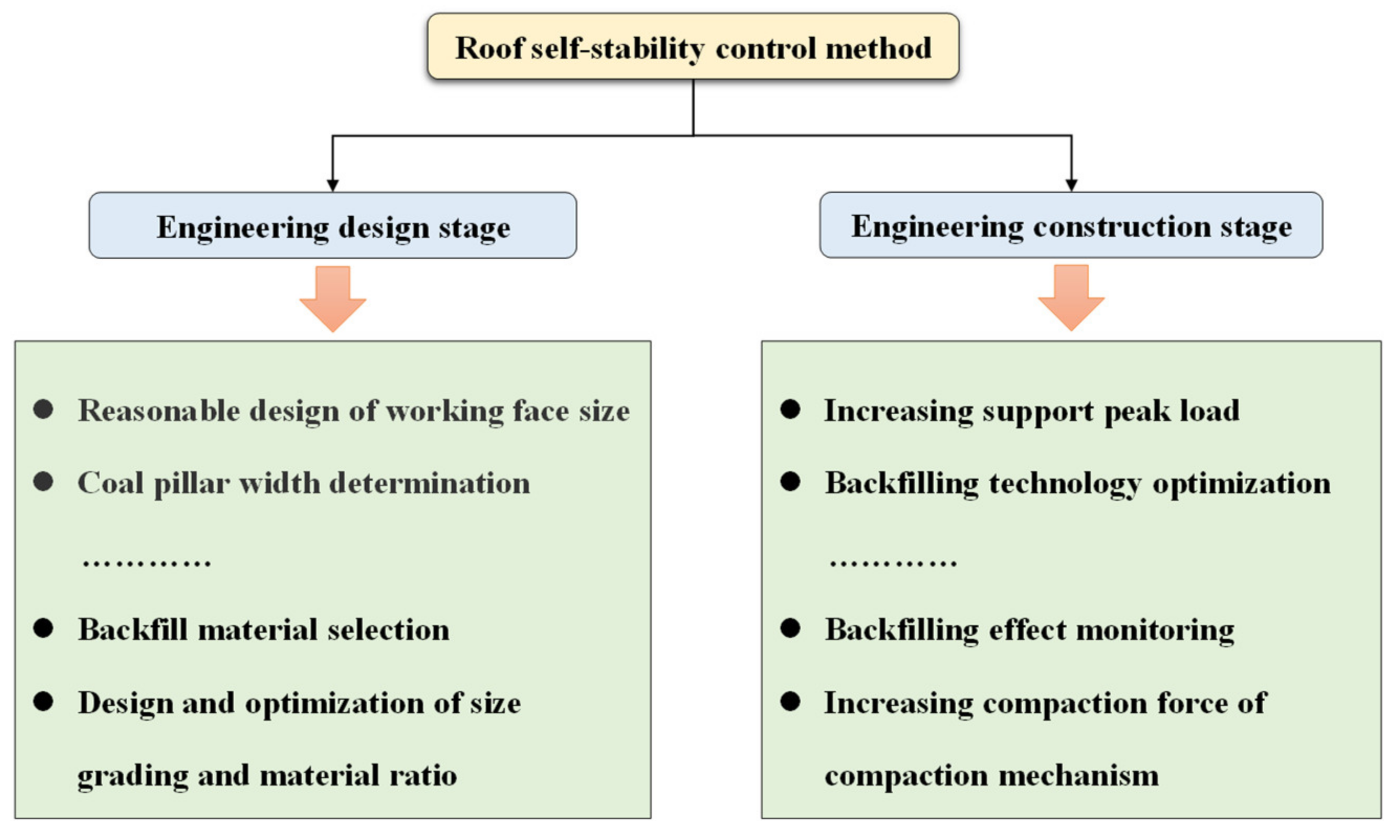
5.1. Engineering Design Stage
- (1)
- The above mechanical model analysis shows that the roof self-stability is restrained by the working face length and promoted by the coal-pillar length. Reasonable designs of working-face and coal-pillar sizes are relevant to the geological conditions of mines. When the overlying strata are stable, the working face length can be appropriately increased to decrease the coal-pillar length, and vice versa.
- (2)
- Material selection, size grading, and material ratio play an important role in roof self-stability control. The backfill materials include gangue, aeolian sand, river sand, and fly ash. Different materials have different physical and mechanical properties. The materials with higher strength are more easily to achieve roof self-stability. Gangue is used as a bulk filling material. Different size grading leads to different compression deformation properties. Therefore, the experimental methods are used to select the size grading with optimal deformation resistance at the engineering design stage. The material ratio plays an important role in roof self-stability as one of the key factors affecting the deformation resistance of the backfilling body. Therefore, the material ratio needs to be optimized.
5.2. Engineering Construction Stage
- (1)
- The backfill technology is accurately implemented by reducing the unsupported-roof distance and increasing the backfilling ratio. The unsupported-roof distance has little influence on roof self-stability. However, the backfilling ratio is one of the main factors for roof self-stability. A larger backfilling ratio leads to smaller roof subsidence and easier achievement of roof self-stability.
- (2)
- Roof stability is promoted by the top beam of the backfilling hydraulic support. The initial support force and working resistance of hydraulic support are increased to reduce the advanced roof subsidence, which ensures the filling space.
- (3)
- Filling effect monitoring is an effective method of determining whether the roof forms a self-stable structure. The roof state is reflected by monitoring the support working resistance, advanced abutment pressure, roof subsidence in the goaf, and backfill stress.
6. Engineering Verification
6.1. Mining Geological Conditions
6.2. Parameter Calculation for Roof Self-Stability Control
6.3. Engineering Verification of Roof Self-Stability
- (1)
- Backfilling hydraulic support strength
- (2)
- Backfill ratio
- ①
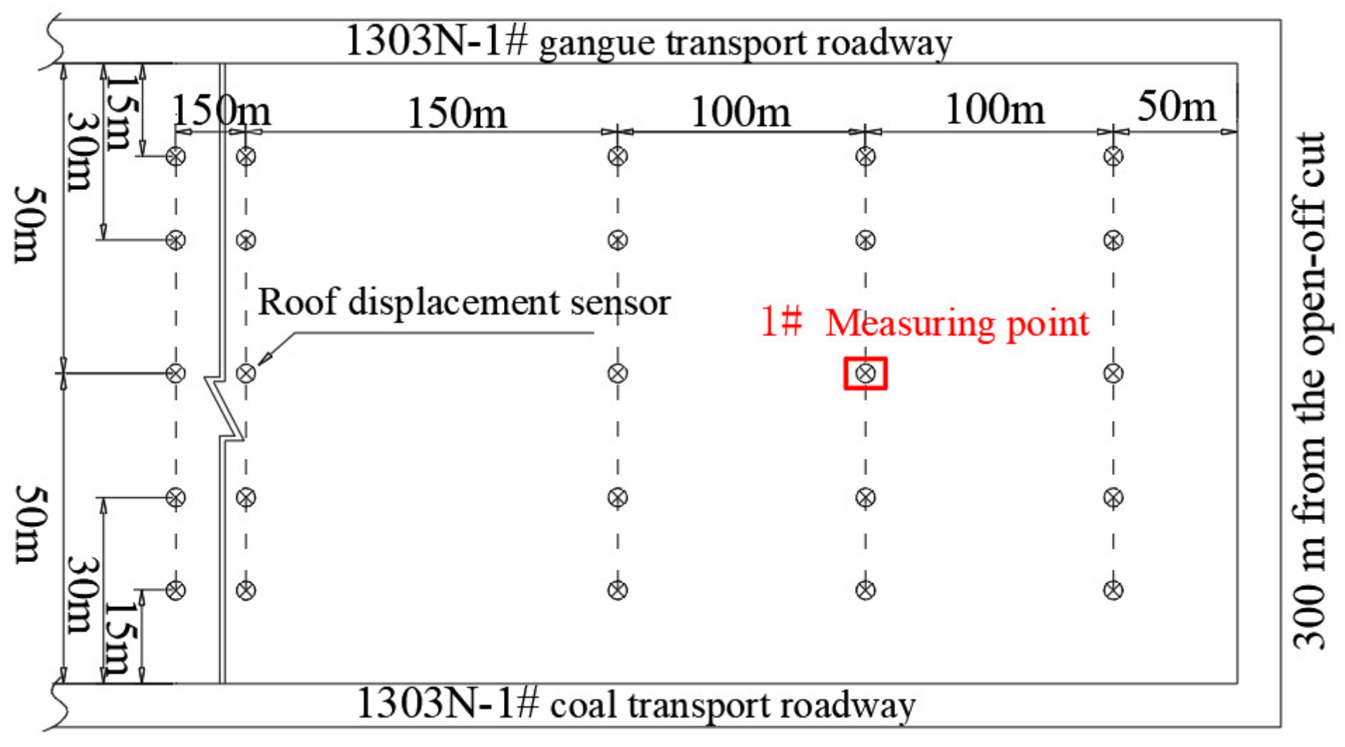
- Measuring-point layout
- (a)
- Dynamic roof subsidence above the goaf is divided into three stages with the advancement of the working face: the accelerated subsidence stage (the distance between the working face and measuring point is 0–88 m); the slowly-increased subsidence stage (the distance is 88–188 m); the creep deformation stage (the distance > 188 m).
- (b)
- The backfilling body is not compacted in time with the increased advancing distance at the accelerated subsidence stage. The overlying strata cannot be supported by the backfilling body, which accelerates roof subsidence. The dynamic backfill ratio of the roof is 89.78% when the working face is 88 m away from the measuring point (the working face is advanced by 538 m). A stable roof structure leads to its bending subsidence.
- (c)
- The backfilling body is gradually compacted with the increased advancing distance at the slowly-increased subsidence stage. The compaction rate continuously decreases. The roof subsidence rate is lower than the compaction rate at the accelerated deformation stage of surrounding rocks. The roof bending amplitude increases, but no caving failure occurs.
- (d)
- When the distance between the working face and measuring point is larger than 188 m (the advanced distance is larger than 638 m), the roof subsidence enters the creep deformation stage of surrounding rocks. The backfilling body is gradually compacted to bear a load of overlying strata with the advanced working face, which stabilizes the roof subsidence. When roof subsidence is stable, the foundation coefficient of the backfill material is 4.16 × 10⁸ Nm−3; the maximum subsidence at measuring point 1# is 438 mm. The backfill ratio at measuring point 1# is calculated to be 86.3%, which is greater than the roof self-stability condition. Therefore, the roof forms a self-stable structure.
7. Conclusions
- (1)
- The concept and connotation of roof self-stability were proposed by analyzing the roof structure types along the strike and dip of coal seams and under different backfill degrees. After that, the structural characteristics of self-stable rock beams were expounded from the perspectives of roof stress distribution, overburden subsidence, and energy transfer.
- (2)
- A mechanical model of roof self-stability along strike was established based on the elastic-foundation beam theory to analyze the effect laws of backfilling elastic-foundation coefficients, supporting-peak loads, and unsupported-roof and advancing distances on roof self-stability along strike. Roof stability was greatly impacted by backfilling elastic-foundation coefficient and slightly impacted by supporting-peak load and advancing distance. Unsupported-roof distance had no obvious effect on roof stability. A mechanical model of roof self-stability along dip was established to analyze the effect laws of the working face and coal-pillar lengths on roof stability. The working face and coal-pillar lengths significantly affected roof breakage. The reserved coal-pillar length was appropriately reduced within a certain range.
- (3)
- The control method of roof self-stability engineering was put forward at the engineering design and construction stages according to the analysis of the roof self-stability effect.
- (4)
- The control parameters for roof self-stability were calculated combined with the geological and mining conditions of the Xinjulong Coal Mine. Roof self-stability conditions were satisfied when the supporting intensity of backfilling hydraulic support was greater than 0.93 MPa; the backfill ratio was greater than 84.6%. Engineering practice showed that the maximum roof subsidence was 438 mm, and the backfill ratio was 86.3% when the supporting intensity of backfilling hydraulic support was 0.94 MPa; the advancing distance of the working face was greater than 638 m; the foundation coefficient of backfill material was 4.16 × 10⁸ N·m−3. The roof formed a self-stabile structure, which met the requirements of coal mining under buildings, water bodies, and railways.
Author Contributions
Funding
Institutional Review Board Statement
Informed Consent Statement
Data Availability Statement
Acknowledgments
Conflicts of Interest
References
- Jialin, X. Research and Progress of Coal Mine Green Mining in 20 Years. Coal Sci. Technol. 2020, 48, 1–15. [Google Scholar]
- Xikui, S. Present Situation and Prospect of Green Backfill Mining in Mines. Coal Sci. Technol. 2020, 48, 48–55. [Google Scholar]
- Ke, Y.; Zhen, W.; Xinyuan, Z.; Xiang, H.; Jiqiang, Z.; Jianshuai, J. Theory and Technology of Green Filling Mining of Solid Waste Underground in Coal Power Base of Yellow River Basin. J. China Coal Soc. 2022, 46, 1–14. [Google Scholar]
- Jiangong, L.; Xinwang, L.; Tuan, H. Application Status and Prospect of Backfill Mining in Chinese Coal Mines. J. China Coal Soc. 2020, 45, 141–150. [Google Scholar]
- Jixiong, Z. Study on strata movement controlling by raw waste backfilling with fully-mechanized coal winning technology and its engineering applications. Xuzhou China Univ. Min. Technol. 2008, 48, 55. [Google Scholar]
- Xiexing, M.; Jixiong, Z.; Guangli, G. Study on waste-filling method and technology in fully-mechanized coal mining. J. China Coal Soc. 2010, 35, 1–6. [Google Scholar]
- Qiang, Z.; Kang, Y.; Hao, Z.; Kangqi, X.; Qi, Z. Research on Weakening Law and Quantitative Characterization of Strata Behavior in Solid Filling Mining. J. China Univ. Min. Technol. 2021, 50, 479–488. [Google Scholar]
- Qiang, Z.; Kang, Y.; Jixiong, Z.; Wei, Y.; Xianwei, L.; Zhongya, W.; Weijian, S.; Xiling, X. Monitoring and Measurement Analysis of Key Indexes for The Implementation of Mining, Dressing, Backfilling, and Controlling Technology in Coal Resources—A Case Study of Tangshan Mine. Energy Sci. Eng. 2022, 10, 680–693. [Google Scholar] [CrossRef]
- Qiang, Z.; Kang, Y.; Jixiong, Z.; Hao, Z.; Zihao, W.; Xiuguo, T.; Guiyun, L. Immediate Roof Control Mechanism in Solid Backfill Mining Method and Its Engineering Case. J. China Univ. Min. Technol. 2022, 51, 35–45. [Google Scholar]
- Kaikai, G. Research on Strata Movement Rule and Control in Deep Solid Backfilling Mining. Ph.D. Thesis, China University of Mining & Technology, Beijing, China, 2021. [Google Scholar]
- Jiangong, L.; Jiawei, Z.; Mengmeng, L.; Jianping, Z. Continuous Curved Beam Formation and Strata Control Theory in Coal Backfill Mining. J. China Coal Soc. 2016, 41, 383–391. [Google Scholar]
- Jiangong, L.; Jiawei, Z.; Hongzeng, Y. Study on The Time and Space Characteristics of Continuous Curved Beam Under Backfilling Mining Condition. Coal Sci. Technol. 2017, 45, 41–47. [Google Scholar]
- Jianping, Z.; Yu-bo, Z.; Guangwen, L.; Guangyao, S.; Yue, S. Continuous Deformation Law and Curvature Model of Rock Strata in Coal Backfill Mining. Rock Soil Mech. 2019, 40, 1097–1104, 1220. [Google Scholar]
- Qiang, Z.; Jixiong, Z.; Jiaqi, W.; Peng, H.; Meng, L.; Hao, Y. Theoretical Research and Its Engineering Practice on Critical Backfill Ratio in Backfill Mining. J. China Coal Soc. 2017, 42, 3081–3088. [Google Scholar]
- Peng, H.; Xingjun, Z.; Yuming, G.; Ailing, L.; Qiang, Z. Study on Control Effect of Roof Based on Backfilling Body Cooperating with Support. J. Min. Saf. Eng. 2020, 37, 128–135. [Google Scholar]
- Peng, H.; Jixiong, Z.; Yuming, G.; Meng, L.; Qi, Z. Viscoelastic Effect of Deep Gangue Backfill Body and Time-Dependent Deformation Characteristics of Roof in Deep Mining. J. China Univ. Min. Technol. 2021, 50, 489–497. [Google Scholar]
- Lichun, J.; Peng, C.; Aixiang, W. Roof Self-stabilizing Arching Effect of Goaf Based on Different Roof-contacted Filling Rate. Chin. J. Nonferrous Met. 2019, 29, 187–193. [Google Scholar]
- Yunjiang, S.; Chengyi, X.; Jianping, Z.; Mengmeng, L.; Yue, S.; Yubo, Z. Mechanical Model of Rock Strata Continuous Bending Movement Under Non-Uniform Load in Backfill Mining. Coal Sci. Technol. 2020, 48, 139–145. [Google Scholar]
- Meng, L.; Jixiong, Z.; Peng, H.; Jiaqi, W.; Yuyao, W. Control Factors of Stope Roof Subsidence in Deep Gangue Backfill Mining and Its Influence Law. J. Min. Saf. Eng. 2022, 39, 227–238. [Google Scholar]
- Pengfei, W.; Bing, L.; Yu, Y.; Jiaxu, J.; Gang, L.; Beifang, W.; Bin, G. Collaborative bearing mechanism and filling effect evaluation of gangue filling mining. J. Min. Saf. Eng. 2022, 39, 239–247. [Google Scholar]
- Chaojun, F.; Sheng, L.; Long, H.; Wenzhang, D.; Zhenghua, Y. Structure and Deformation Law of Overlying Strata for Waste Rock-fly Ash Backfilling Mining. Chin. J. Undergr. Space Eng. 2018, 14, 117–123. [Google Scholar]
- Yang, C. Strata Roof Self Stability Model and Its Engineering Application for Precise Control of Strata in Backfill Mining. Master’s Thesis, China University of Mining & Technology, Wudaokou, China, 2021. [Google Scholar]
- Guangli, G.; Kaikai, G.; Guojian, Z.; Huaizhan, L.; Shaohao, H. Research on Deformation Characteristics of Coupled Coal-backfills Bearing in Deep Strip Backfilling Mining. J. Min. Saf. Eng. 2020, 37, 101–109. [Google Scholar]
- Baozhu, H.; Yueguan, Y.; Guoping, M.; Xiu-guo, T.; Wanqiu, Z.; Ziyu, J.; Ming, L. Deformation Law of Overlying Strata and Coal Pillar in Coordinated Backfilling-retaining Mining in Tangshan Mine. Coal Eng. 2021, 53, 115–120. [Google Scholar]


| Item | Precise Backfilling | Long-Wall Caving |
|---|---|---|
| Strata control diagram | 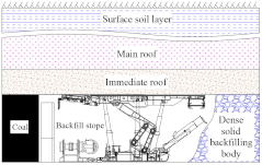 | 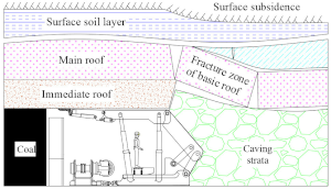 |
| Goaf | Dense backfilling body | Collapsed bulk gangue |
| Immediate roof | Mining and bending (collapses) | Mining and collapses |
| Basic roof | Breakage may not occur (depending on the filling density) | First and periodic breakage |
| Rock beam structure after mining |  | 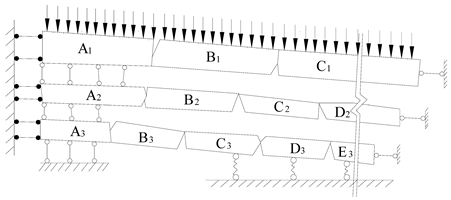 |
| Continuous bending beam: it is a beam although looking like a beam | Masonry beam: it is an arch although looking like a beam | |
| Reconstruction of equilibrium states | Curved arch | Three-hinged arch |
| Determination of motion states | Bending self-stability | S (slip)-R (roll) instability |
Publisher’s Note: MDPI stays neutral with regard to jurisdictional claims in published maps and institutional affiliations. |
© 2022 by the authors. Licensee MDPI, Basel, Switzerland. This article is an open access article distributed under the terms and conditions of the Creative Commons Attribution (CC BY) license (https://creativecommons.org/licenses/by/4.0/).
Share and Cite
Zhang, Q.; Yang, K.; Zhang, J.; Wang, Q.; Yuan, L.; Shi, Z.; Xu, X. A Theoretical Model of Roof Self-Stability in Solid Backfilling Mining and Its Engineering Verification. Appl. Sci. 2022, 12, 12114. https://doi.org/10.3390/app122312114
Zhang Q, Yang K, Zhang J, Wang Q, Yuan L, Shi Z, Xu X. A Theoretical Model of Roof Self-Stability in Solid Backfilling Mining and Its Engineering Verification. Applied Sciences. 2022; 12(23):12114. https://doi.org/10.3390/app122312114
Chicago/Turabian StyleZhang, Qiang, Kang Yang, Jixiong Zhang, Qi Wang, Longfeng Yuan, Zengzhu Shi, and Xiling Xu. 2022. "A Theoretical Model of Roof Self-Stability in Solid Backfilling Mining and Its Engineering Verification" Applied Sciences 12, no. 23: 12114. https://doi.org/10.3390/app122312114
APA StyleZhang, Q., Yang, K., Zhang, J., Wang, Q., Yuan, L., Shi, Z., & Xu, X. (2022). A Theoretical Model of Roof Self-Stability in Solid Backfilling Mining and Its Engineering Verification. Applied Sciences, 12(23), 12114. https://doi.org/10.3390/app122312114