1. Introduction
In optics, cylindrical vector beams (CVB) are well known [
1,
2], including high-order beams. When the order is
n = 1, these beams have specific names—radially polarized beam [
3] and azimuthally polarized beam [
4]. In addition, a lot of works studied sharp focusing of CVBs of the first order [
5,
6], of the high order [
7,
8], of the fractional order [
9], as well as focusing of the vortex beams with high-order azimuthal polarization [
10]. There are a lot of different ways to generate cylindrical vector beams by using, for instance, Twyman Green interferometer [
11], Dammann gratings [
12], metasurface [
13,
14], spatial light modulator [
15], or elements fabricated by digital laser printing [
16,
17].
It is known that both in the initial plane and in the focus of a CVB of an arbitrary order, polarization is inhomogeneous and linear in every point of the beam’s cross-section. The beam order
n is equal to the number of full rotations of the polarization vector when passing along a closed contour around the optical axis. On the optical axis in the initial plane, such beams have a point of a polarization singularity (V-point), where the direction of the linear polarization vector [
18] is undefined. The polarization index of this V-point is equal to the beam order
n. It is also known that in the sharp focus of the
nth-order CVB, the intensity distribution has 2(
n−1) local maxima [
18]. The third component of the Stokes vector is zero:
, i.e., the spin angular momentum (SAM) of a CVB in the initial plane is zero. Equal to zero is also the orbital angular momentum (OAM) of the CVB in the initial plane and in the focus.
In this paper, using the Debye integrals and a numerical simulation, we show that near the sharp focus (before the focus and beyond the focus), local subwavelength areas are generated with elliptic and circular polarization of a different sign.
2. Spin Angular Momentum before and beyond the Focus
If the initial light field is an
nth-order cylindrical vector beam, the Jones vectors of the electric and magnetic fields are given by:
with (
r, φ) being the polar coordinates in the transverse initial plane of the beam.
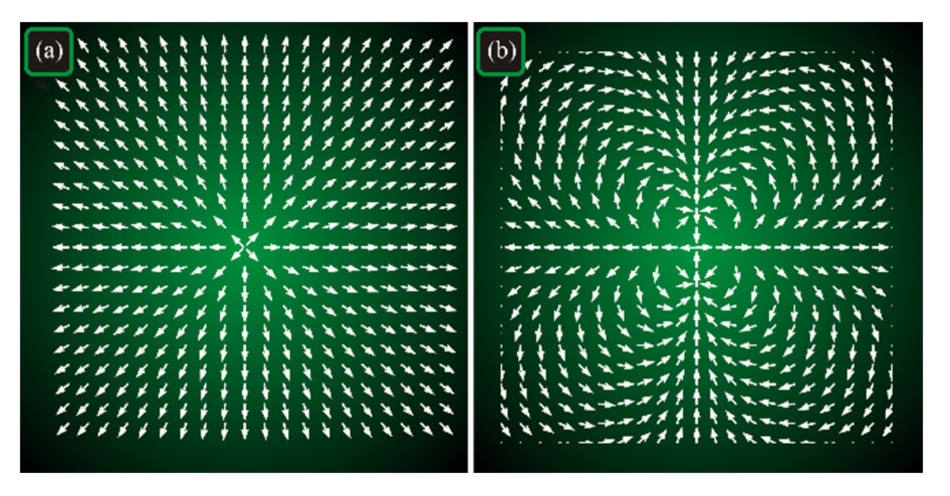
Figure 1 depicts the intensity distribution of a Gaussian beam and the electric field strength vectors, when the beam has cylindrical polarization (1) with
n = 1 and
n = 3.
It is seen in
Figure 1 that on a closed contour around the field, the polarization vector makes one full rotation in
Figure 1a and three full rotations in
Figure 1b. Thus, on space propagation and in the focus, the field in
Figure 1a (
n = 1) should retain its rotational symmetry, whereas 3rd-order cylindrical polarization (
n = 3,
Figure 1b) violates this rotational symmetry.
Adopting the Debye integrals [
19], we derive all the Cartesian components of the strength vectors of the electric and magnetic fields in the sharp focus of the light field with polarization (1):
In Equation (2), the functions
Iν,µ depend only on the radial and longitudinal coordinates
r and
z and equal to:
where
k = 2π/λ stands for the wavenumber of monochromatic light with the wavelength λ,
f is the focal distance of an aberration-free spherical lens that focuses the beam,
z is the propagation axis (
z = 0 is the focal plane), ξ
= kr sin θ is a dimensionless argument of the μth-order Bessel function of the first kind
Jμ(ξ),
NA = sin θ
0 is the numerical aperture of an aplanatic focusing system, whereas an arbitrary real-valued function
A(θ) describes the amplitude of an input field with a cylindrical symmetry (plane wave, Gaussian beam, Bessel–Gaussian beam). In the functions
Iν,µ in Equation (3), the first index
ν = 0, 1, 2 describes the first part of the integrand, whereas the second index
μ = 0, 1, 2,…,
n defines the order of the Bessel function.
To derive the focal distribution of the spin density or the spin angular momentum (SAM) for the beam with polarization (1), we use the general expression for the spin angular momentum vector given in [
20]:
where ω is the angular frequency of light. From now on, the constant factor 1/(16π
ω) will be omitted. It is seen in Equation (4) that the longitudinal SAM component (without the constant factor) is coinciding with the non-normalized third Stokes parameter
S3:
It is known that the third Stokes component indicates circular or elliptic polarization of a light field [
21]. If
S3 = 0, then the field has only linear polarization. If we substitute the electric field components from Equation (2) into Equation (5) and take into account that the integrals (3) are complex-valued near the focus (but not in the focus itself), we obtain the longitudinal component of the SAM vector:
where the asterisks “*” mean the complex conjugation. Separating the real and imaginary parts in the integrals (3), and using the linear approximation
near the focus (
kz << 1), instead of Equation (6) we get:
where we use the following designations:
As seen from Equation (7), in the focus itself (
z = 0),
S3 = 0, and, therefore, in each point of the focal plane, polarization is linear. However, at small defocusing (
kz << 1),
S3 ≠ 0, and areas with elliptic and circular polarization appear, if
n ≠ 1. The condition
n ≠ 1 is consistent with
Figure 1, demonstrating that the order
n = 1 does not break the rotational symmetry of the beam and the areas with nonzero SAM cannot appear. Thus, such areas can appear only due to the symmetry violation at
n ≠ 1. In the areas where before the focus (
z < 0) the SAM was negative (
S3 < 0), after the focus (
z > 0) it becomes positive (
S3 > 0), and vice versa. According to Equation (7), near the focal plane, on a certain radius circumference with the center on the propagation axis, centers of 4(
n–1) local subwavelength areas reside, with elliptic and circular polarization. In such neighboring areas, the polarization vector is rotating in opposite directions (clockwise or counterclockwise). A similar result was obtained in [
22], but for
n = 0. Since, at
n ≠ 1, near the focus of the light field (1), areas with left and right circular polarization (areas with a different “spin”) are spatially separated, we can conclude that near the focus (before and after it), the spin Hall effect occurs, although in the focal plane itself, this effect vanishes.
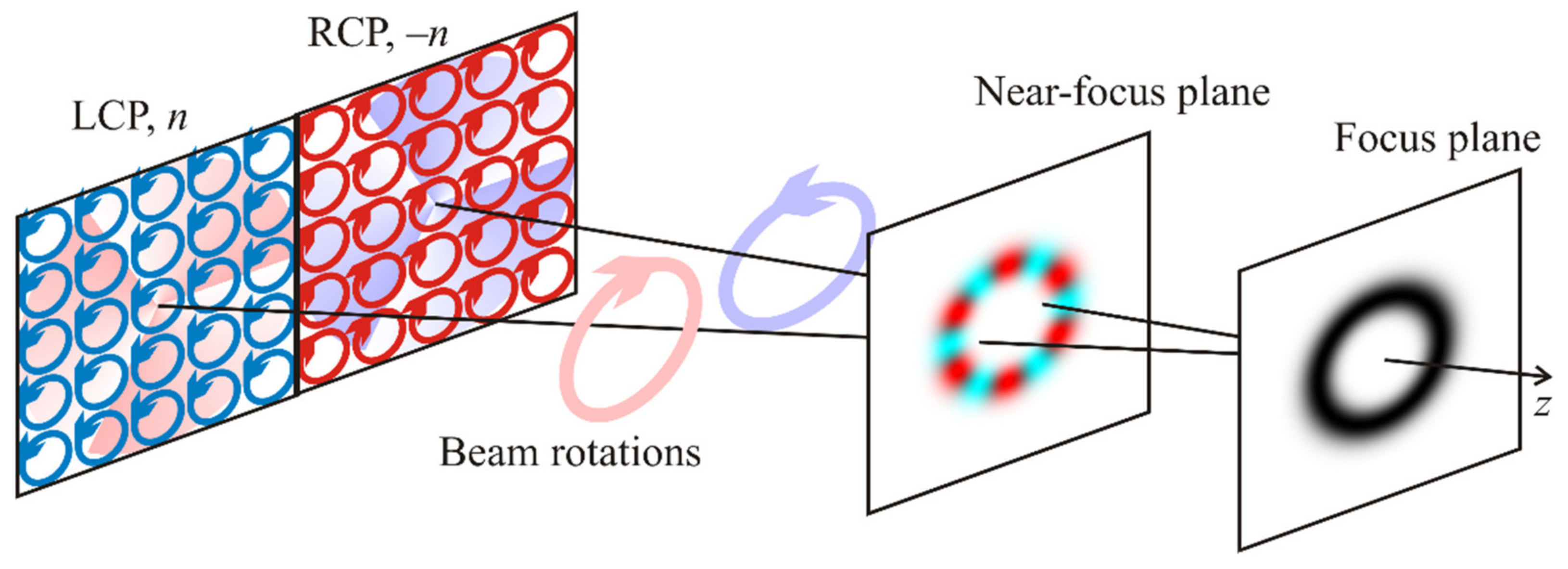
This effect can be approximately explained by decomposing the cylindrical vector beam (1) into a superposition of two circularly polarized optical vortices:
Both optical vortices have the SAM and the OAM. If
n = 1, the SAM and the OAM annihilate each other, and the angular momentum of each vortex is zero. Thus, both vortices do not rotate on propagation and focusing, and the areas with a positive and with a negative SAM are not separated in space. If, however,
n ≠ 1, the angular momentum of each vortex is nonzero and, therefore, both beams rotate on propagation (
Figure 2, beam rotations), i.e., there is a transverse (azimuthal) energy flow in each vortex. Since the vortices are of opposite orders
n and –
n and their circular polarizations are also opposite, the azimuthal energy flows of both vortices are also opposite and, in the transverse plane, they interfere with each other, thus generating the areas with the opposite SAM (
Figure 2, near-focus plane). In the focal plane itself, however, these transverse energy flows annihilate each other, and the SAM is zero in each point (
Figure 2, focus plane).
3. Transverse Energy Flow before and beyond the Focus
We further derive the transverse components of the energy flow vector. The Poynting vector reads as [
19]:
In Equation (9), vectors
E and
H stand, respectively, for the electric and magnetic fields, the asterisk * means the complex conjugation, × is the cross product, and
c is the free-space speed of light. From now on, the constant factor
c/(4π) will be omitted. Substituting the expressions (2) for the electromagnetic field components in the focus into Equation (9), we obtain the transverse components of the Poynting vector near the focus:
Separating the real part and the imaginary part in the integrals (3), and using the approximation
near the focus (
kz << 1), instead of Equation (10) we get:
In Equation (11), the following designations are introduced for the real and imaginary parts of the integrals (3):
For demonstrative purposes, we now move to the polar coordinates. Then, instead of Equation (11), we derive the radial and azimuthal components of the transverse Poynting vector near the focus:
The radial and azimuthal components of the transverse Poynting vector describe, respectively, the convergence/divergence of the light field. Expression (13) illustrates that, regardless of the beam order n, the energy flow near the focus of the beam (1) is diverging or converging from the optical axis along the radial paths. At z = 0 (in the focus), the energy flow is parallel to the optical axis. Before the focus (z < 0), the transverse energy flow is converging along the radii to the optical axis, whereas after the focus (z > 0), it is diverging. Since the sign of the function Q(r) in Equation (13) can change at some distances from the optical axis, then at certain circles centered on the propagation axis, the transverse energy flow is diverging before the focus and converging after the focus.
Now we show for the field with polarization (1) that its longitudinal component of the angular momentum vector is equal to zero near the focus, as in the initial plane. Indeed, the angular momentum vector of light is given by [
23]:
whereas its longitudinal component (without the insignificant constant factor) is
Expression (15) follows from Equation (13), since
Pφ = 0. The angular momentum (14) can be represented [
24] as a sum of the spin angular momentum
S and the orbital angular momentum
L:
Without the constant factor 1/(8πω), the longitudinal SAM component, as follows from Equation (7), is equal to
The longitudinal OAM component from Equation (16) is given by:
Substituting the expressions (2) for the electric field components into Equation (17), we have that near the focus:
Summation of Equations (7) and (18) prove the validity of expression (15). Thus, near the focus, longitudinal SAM and OAM components are equal by magnitude and directed oppositely (Sz = –Lz), and, therefore, the longitudinal component of the angular momentum is equal to zero. It is interesting that, when passing through the focus, the longitudinal OAM component (18) changes its sign, as does the longitudinal SAM component (7).
Thus, since the transverse energy flow near the focus is not rotating (
Pφ = 0), the longitudinal component of the angular momentum equals zero, but it does not mean that, near the focus of the field (1), the longitudinal OAM component is also equal to zero. The field with polarization (1) in the focus has a longitudinal OAM component, equal by the absolute value to the longitudinal SAM component, but with the opposite sign. We also note that the full (averaged along the whole beam cross-section) SAM and OAM are the quantities that conserve separately on free-space propagation of light [
25], so that near the focus of the beam (1), the following two integrals should be equal to zero:
This means that local rotation of the polarization vector near the focus (7) should change signs in different areas of the beam transverse section so that it compensates this rotation and so that the full SAM and OAM of the beam (1) would be equal to zero (19).
4. Numerical Simulation
To confirm the theoretic findings, we performed a numerical simulation. For this purpose, we computed the electric and magnetic fields near the sharp focus by using the expressions (2) and verified them by computing the field directly using the Debye double integrals.
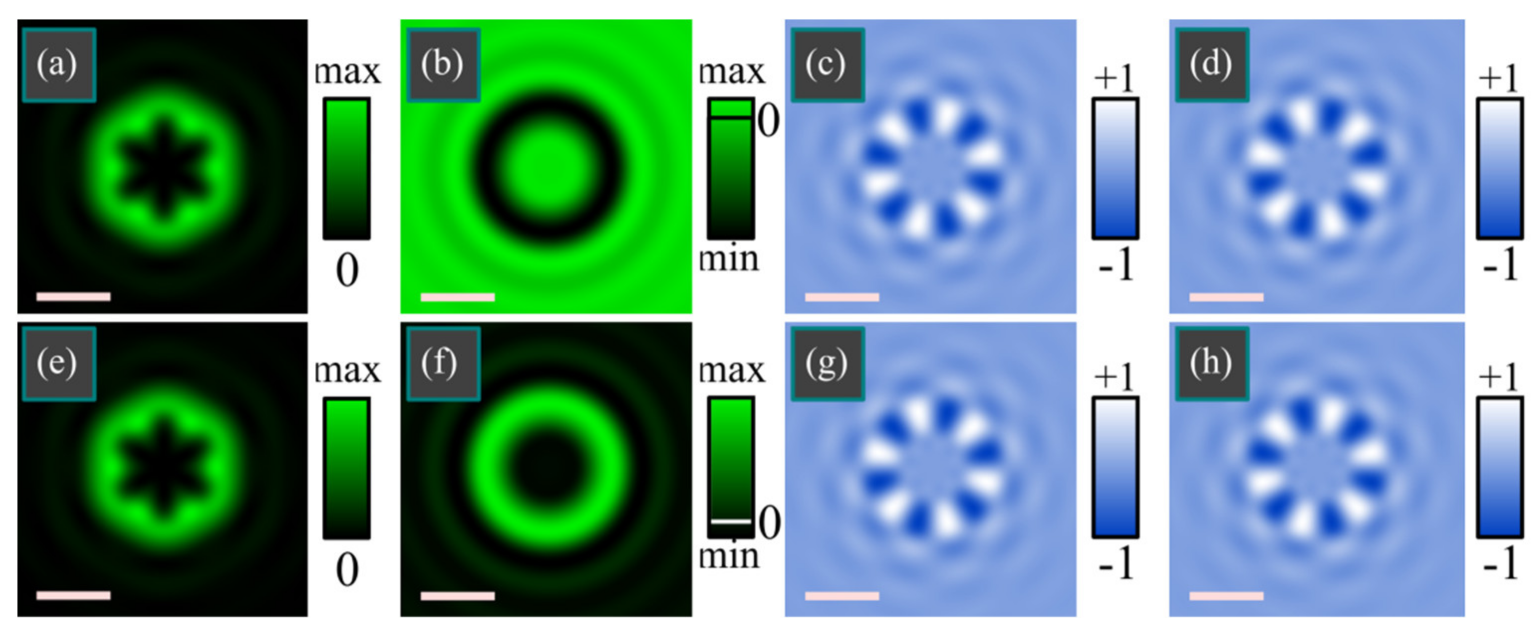
Figure 3 illustrates the distributions of intensity (
Figure 3a,e), radial component of the Poynting vector (
Figure 3b,f), longitudinal components of the SAM (
Figure 3c,g), and OAM (
Figure 3d,h) vectors of a sharply focused Gaussian beam with 3rd-order (
n = 3) cylindrical polarization (1) in two transverse planes, one before the focus (
Figure 3a–d) and one beyond the focus (
Figure 3e–h). For computation, we used the following parameters: wavelength λ = 532 nm, focal length
f = 10 μm, numerical aperture θ
0 = 0.49π (NA = 0.999), calculation area is 4 × 4 μm, the longitudinal coordinate (relative to the focal plane) is
z = –λ (
Figure 3a–d) and
z = +λ (
Figure 3e–h). To describe the Gaussian shape of the input field, radial distribution of the complex amplitude was equal to
A(θ) = exp[–(sin θ/sin α
0)
2] with α
0 = π/3.
Figure 4 depicts the same distributions and the same parameters as in
Figure 3, but for another polarization order
n = 4.
Despite the visual similarity of SAM and OAM distributions (columns 3 and 4 in
Figure 3 and
Figure 4), they were computed quite differently: SAM distributions were computed by Equation (5), whereas the OAM distributions were computed by Equation (17) with numerical differentiation by the angular coordinate φ. Nevertheless, the obtained patterns confirm that the OAM
Lz and the SAM
Sz compensate each other, and that after passing the focal plane, the rotation of the polarization vector changes its direction (i.e., longitudinal SAM component changes its sign).
Figure 3 and
Figure 4 also confirm that, near the focus, there are 4(
n−1) areas with a different rotation direction of the polarization vector.
Figure 3 contains 4(
n−1) = 8 local subwavelength areas with elliptic polarization (
Figure 3c,g), including 4 dark areas with left elliptic polarization and 4 light areas with right elliptic polarization. In
Figure 4, there are 4(
n−1) = 12 such subwavelength areas. Thus, the simulation confirms that the areas with a different “spin” are spatially separated near the focus, which means that the Hall effect occurs.
5. Conclusions
It is known that in the cross-section of a high-order cylindrical vector beam (CVB), polarization is locally linear. The number of full rotations of the locally linear polarization vector, when passing along a closed contour around the optical axis, is equal to the CVB order, for instance,
n. It is also known that both in the initial plane and in the focus, the CVB has neither the spin angular momentum (SAM), nor the orbital angular momentum (OAM). In this work, we demonstrated that near the focal plane of the CVB, for instance, at a distance of wavelength before and beyond the focus, 4(
n−1) local subwavelength areas are generated, where the polarization vector is rotating in each point. These areas appear because, at
n ≠ 1, cylindrical polarization violates the rotational symmetry of the focused beam. The centers of these local areas reside on a certain-radius circle with the center on the optical axis. Furthermore, in the neighboring areas, the polarization vector is rotating in different directions so that the longitudinal component of the SAM vector in the neighboring areas has opposite signs. The full SAM, obtained by averaging the SAM density over the whole transverse section of the beam, is equal to zero. Such space separation of the left and right rotation of the polarization vectors manifests so that the optical spin Hall effect takes place. Such a phenomenon can be used in optical sensorics for determining the CVB order. For example, metasurface-based optical sensors are known [
26,
27,
28,
29], that detect left-handed and right-handed circular polarizations by separating them in space. In our case, the CVB order
n is determined by counting the local areas with left and right circular polarization near the sharp focus. Among other applications of the optical spin Hall effect are spin-dependent beam splitting [
30], surface sensing [
31], and determining biomolecular concentration [
32].

 ,
, 