Abstract
The performance of robot admittance control depends heavily on environmental dynamics, the desired impedance selection, and control input. In this study, an adaptive robust admittance control strategy is proposed for robot–environment interaction. The environmental impedance is estimated using an adaptive law with projection modification to guarantee that the impedance estimator is constrained in a predefined set. Then, the desired robot stiffness and damping are determined based on the duality principle. To obtain the desired impedance dynamics, an adaptive robust admittance controller based on time-delay estimation is designed for the robot to track the admittance trajectory with the prescribed performance. Simulations are conducted to show the effectiveness of the environmental impedance estimation and the proposed adaptive robust admittance control.
1. Introduction
As powerful active compliance control approaches, hybrid positon/force control and impedance/admittance control have been widely applied in assembling, grinding, polishing, and human–robot interaction. In hybrid position/force control, the task space is decomposed into orthogonal position-controlled and force-controlled subspaces [1,2]. The control implementation requires significant task planning and control-law switching and suffers from control robust problems. Impedance control [3,4,5] provides impedance regulation for robots through the dynamic relationship between the robot position and the interactive force, which is called “desired impedance” and is defined by the users. Compared with hybrid position/force control, impedance control can be conducted without complex offline task planning and can provide robustness to uncertainties and disturbances [6,7,8,9]. The difficulties in robot impedance/admittance control mainly lie in the determination of the desired impedance and robot control design to realize the desired impedance dynamics.
The performance of robot–environment interaction by impedance/admittance control depends heavily on environmental dynamics and the desired impedance, which shows the significance of the selection of the desired impedance. From the viewpoint of power transformation, the desired impedance can be chosen equal to environmental impedance to transfer maximum power from the robot to the environment. From a stability viewpoint, robot impedance should conceptually be equal to environmental admittance to realize rigid-flexible coupling [3], which has been acknowledged by the duality principle for impedance selection [10]. In a similar manner, the desired stiffness has been designed as proportional to the reciprocal of the environmental stiffness in [11]. However, the selection of the desired impedance [10,11] requires the knowledge of environmental impedance, which is usually unknown in many applications. To facilitate the robotic impedance selection, estimations of environmental stiffness and damping have been conducted based on the signal processing method, recursive least-squares method, and Lyapunov-based adaptation [12,13,14], without estimators being contained in the prescribed sets.
Robot modeling uncertainties and disturbances are the main difficulties for robots in realizing the desired impedance dynamics. How to improve control robustness [15] for robot impedance/admittance control is an important issue to be solved. Impedance control is achieved with a force-controlled outer loop and a position-controlled inner loop and is better suited for interaction with stiff environments [16,17], whereas admittance control is achieved with a position-controlled outer loop and a force-controlled inner loop and is better suited for interaction with soft environments. Therefore, the ways to tackle modeling uncertainties and disturbances are different for impedance control and admittance control. Impedance control robustness is improved mainly by enhancing robot modeling accuracy, whereas admittance control robustness is enhanced through position control based on an adaptive control approach, a sliding-mode control approach, iterative learning, neural networks, and fuzzy logics [18,19,20,21,22]. However, adaptive control requires robot dynamic parameterization, sliding-mode control has an inherent chattering problem, iterative learning is mainly applied in systems with periodicity characteristics, and the complexities of neural networks and fuzzy logics limit their applications in real-time control. Through time-delay estimation (TDE) [23,24,25], time-delay control can compensate for complex robot dynamics without a robot dynamics model. In addition, time-delay control is simple in structure and numerically efficient and has been applied in robot manipulators and exoskeletons. However, discontinuous terms in robotic models, especially the Coulomb friction and static friction, introduce non-negligible time-delay estimation errors and affect control stability and robustness. As sliding-mode control (SMC) is well known for its strong robustness [26,27], it is promising to integrate TDE and SMC to improve control robustness [28]; however, the inherent possible chattering problem of SMC limits its applications.
In this study, we propose an adaptive robust admittance control strategy to improve robot–environment interaction. The environmental impedance is estimated using an adaptive law with projection modification to guarantee the impedance estimator constrained in a predefined set. Then, the desired robot stiffness and damping are determined based on the duality principle. To obtain the desired impedance dynamics, an adaptive robust admittance controller based on TDE is designed for the robot to track the admittance trajectory with the prescribed performance. In the adaptive robust controller, the possible chattering problem is highly alleviated due to the use of the saturation function instead of the conventional SMC. Simulations are conducted to show the effectiveness of the environmental impedance estimation and the proposed adaptive robust admittance control.
Compared with the environmental impedance estimation in [12,13,14], the projection modification-based adaptive impedance learning law can guarantee that the estimated environmental stiffness and damping are constrained in prescribed sets, which is of significant value for the determination of the range of the desired robot impedance. Compared with the TDE-based SMC in [28] for position regulation, the designed adaptive robust admittance controller can make robots realize the desired impedance dynamics without serious chattering and the requirement of the bound of the TDE error.
2. Problem Statement
Consider the following robotic Cartesian dynamics:
where denote the Cartesian position, velocity, and acceleration at the robot–environment interaction point, respectively; and are the inertia matrix and the Coriolis/centrifugal matrix, respectively; is the gravitational vector; denotes the friction force; denotes the robot–environment interactive force; and the control input satisfies , with J being the Jacobian matrix and u being the torques applied by the motors.
The inertia matrix is symmetric and positive definite and satisfies
where , .
The environment dynamics can be modeled by
where and denote the environmental stiffness and damping, respectively. In a robot–environment interaction, the environmental stiffness and damping are usually assumed as diagonal matrices and can be defined as and , constrained by
with , , , and being positive constants.
From (3), the desired interactive force can be modeled as
where denotes the desired trajectory for the robot corresponding to .
Consider the following desired impedance model:
where denotes the desired trajectory tracking error, and , , and are diagonal positive definite matrices and denote the desired inertia matrix, stiffness matrix, and damping matrix, respectively.
The objectives of this study are: (i) to estimate environmental stiffness and damping using composite adaptation and determine robot stiffness and damping based on the duality principle; (ii) to design adaptive robust admittance control based on time-delay estimation to obtain the prescribed admittance trajectory tracking.
3. Determination of the Desired Impedance Profiles
The determination of the desired robot impedance is closely related to environmental impedance. This section presents an adaptive law with projection modification to estimate the environmental stiffness and damping. Then, the desired stiffness and damping are determined for robots based on the duality principle.
From (3), the interactive force can be presented in the following expression:
where is a regression vector and is an unknown vector defined by
with , , and .
denotes the estimators of . Then, the estimator of can be presented as
and the estimation error is given by
where .
Design the following update law:
where is a positive constant gain and is the function defined by
with being the projection function defined by
Theorem 1.
By the adaptive update law in (12), the estimation error is uniformly ultimately bounded (UUB).
Proof.
Consider the following candidate Lyapunov function:
Substituting (12) into the time derivative of yields
The projection function in (13) guarantees for if . From (11), . Applying these results to (21) yields
from which we can conclude that the estimation error is UUB. □
Based on the duality principle [29], the robot impedance is chosen as the reciprocal of the environmental impedance in the following form:
where .
Substituting (3) and (5) into the desired impedance dynamics (6) yields
To obtain a good performance of in (19), based on the automatic control theory, one can construct the following optimal damping:
where denotes the damping ratio.
By substituting the estimated environmental stiffness into (19), we can obtain the following adaptive optimal stiffness:
Based on (20) and (21), it is convenient for us to design the following desired damping:
4. Robust Adaptive Admittance Control Based on Time-Delay Estimation
In this section, we propose a robust adaptive admittance control for the considered robot to track the following admittance trajectory:
where is the output of the following dynamics:
Define the admittance trajectory tracing error and its filtered error r as
where is a positive definite diagonal matrix.
The robot dynamics in (1) can be rewritten in the following form:
where is a constant matrix and is an uncertainty term defined by
Remark 1.
Submitting (24) to the desired impedance dynamics in (6) yields
from which one can conclude that the desired impedance dynamics can be obtained if is close to zero.
Remark 2.
Based on the time-delay estimation in [23,24,25], the control stability requires that the constant matrix should be chosen such that the eigenvalue of resides inside a unit circle.
Design the control input as
where the control gain is a positive definite diagonal matrix, is an adaptive robust control term to be designed, signifies the value of • at time t, and is the time-delay-based estimation given by
with the time delay L being sufficiently small.
Substituting (30) into (27) yields
where is the estimation error defined by
In [23], the estimation error is bounded, i.e.,
with being an unknown constant.
To improve control robustness, the control term is designed by
where is the saturation function and is a small positive parameter. In (49), is updated by
where the projection function guarantees with being an upper bound.
Remark 3.
Since L is sufficiently small, by choosing it as the sampling period, the estimation error will be sufficiently small if is continuous. However, the friction , including the Coulomb friction and static friction, is discontinuous and may cause a large . Although SMC has strong control robustness, its discontinuity may decrease the time-delay-based estimation accuracy and may lead to the chattering problem. The proposed adaptive robust control term ρ is continuous and does not require the knowledge of the bound .
Theorem 2.
Design the adaptive robust admittance controller in (30) for the considered robot with the dynamics in (1). Then, the tracking error for the admittance trajectory is ultimately bounded by .
Proof.
Define the following non-negative function
where .
Taking the time derivative of V and substituting (32) and (36), one can obtain
If ,
from which one can see that the error r enters the compact set in finite time.
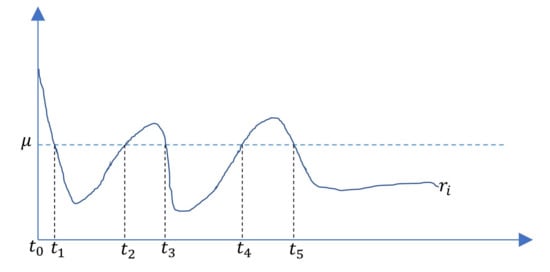
As described in Figure 1, for , let times with odd subscripts denote times at which and is entering the set , whereas times with even subscripts denote times at which and the error is leaving the compact set. Then, one obtains
Figure 1.
The indices on error convergence.
(i) with for ;
(ii) for , from which we further obtain .
N is the number of times that the error r enters the deadzone, where . Then, the total time outside the deadzone satisfies
Therefore, the total time outside the deadzone is finite and is ultimately bounded by .
Solving the differential equation yields
From (41) and ,
Therefore, the proposed control guarantees that the tracking error is ultimately bounded by . □
Remark 4.
The proposed admittance control can guarantee good tracking performance for the admittance trajectory , which further ensures the boundedness of the impedance error and the obtainment of the desired impedance dynamics.
5. Simulations
To verify the proposed methodology, simulations are implemented on a two-DOF planar parallel robot with the mechanism diagram in Figure 2, and the related parameters in Table 1, where are joint points and denotes the interaction point. Driven by the motors located at and , the robot can move cooperatively with the user in the workspace of the robot. Along with the advantages of the parallel mechanism in comparison with the series mechanism, the parallel robot is with a complex model.
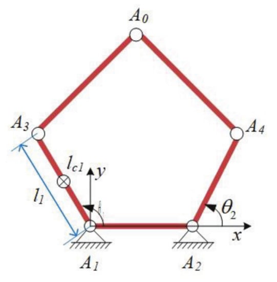
Figure 2.
The structure diagram of the considered robot.

Table 1.
Parameters of the parallel robot.
In the simulation, the friction torque is and the human–robot system requires following the reference trajectory
In the environmental impedance estimation, choose , , , , and . In Figure 3, it can be seen that the estimated stiffness and damping are very close to their actual values , and after 10 s, which shows the effectiveness of the designed projection-based adaptive estimation for the environmental impedance. Based on the estimated stiffness, we choose and for (21) and (22) to construct the desired robot impedance presented in Figure 4.
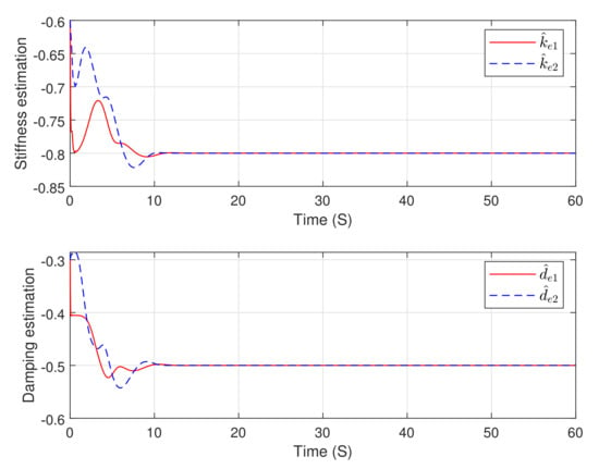
Figure 3.
The estimation performance for the environmental stiffness and damping.
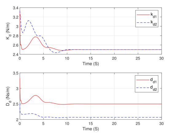
Figure 4.
The desired robot stiffness and damping.
For the proposed adaptive robust admittance controller in (30), choose the following control parameters: , , , and . The proposed controller in Figure 5 with the adaptive gain in Figure 6 makes the tracking error in Figure 7 for the admittance trajectory is very close to zero after 20 seconds, which guarantees the impedance error being very close to zero ultimately and the achievement of the desired impedance dynamics. Figure 8 presents the desired trajectory tracking error and the force tracking error , from which we can see that the designed admittance control develops a dynamic balance between the tracking error and the interactive force. Based on the above analysis, one can conclude the effectiveness of the proposed environmental impedance estimation and adaptive robust admittance control for robot–environment interaction.
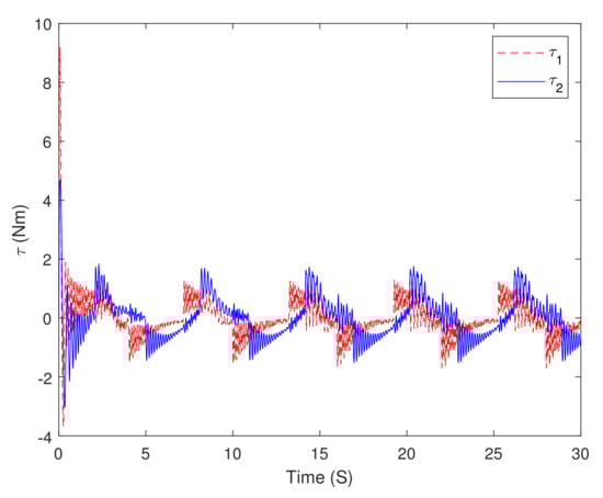
Figure 5.
The proposed adaptive robust admittance controller in (30).
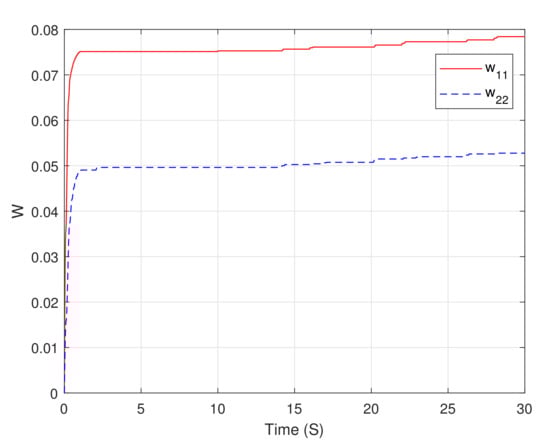
Figure 6.
The adaptive parameters for the adaptive robust control term (35).
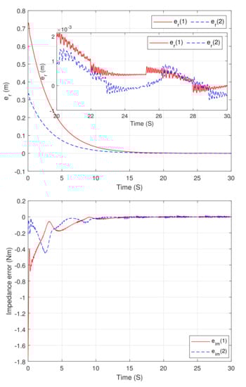
Figure 7.
The tracking performance for the admittance trajectory and impedance error.
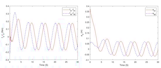
Figure 8.
The performance of the desired trajectory tracking error and the interactive force.
6. Conclusions
In this study, we propose an adaptive robust admittance control for robots using duality principle-based impedance selection to improve robot-environment interaction performance. The main contributions lie in the projection-modification-based adaptive impedance learning and the adaptive robust admittance controller, which helps in the determination of the desired robot impedance and improves the admittance control robustness without chattering. The control implementation includes the following steps: environmental impedance estimation, determination of the desired impedance profiles based on the duality principle, design of the admittance trajectory based on the desired impedance dynamics, and design of the adaptive robust admittance controller.
Since admittance control is achieved with a position-controlled outer loop and a force-controlled inner loop, the proposed adaptive robust admittance control is more suited for interaction with soft environments than stiff environments. The developed method is suitable for interaction with the environment with a constant or slowly varying impedance due to the limitations of the differential adaptation used in impedance learning.
Author Contributions
Methodology, T.S.; Project administration, L.Y.; Validation, Z.W.; Writing, review & editing, C.H. All authors have read and agreed to the published version of the manuscript.
Funding
This work is supported in part by the National Key Research and Development Project (No. 2019YFB1312500), in part by the National Natural Science Foundation of China (Nos. 62073156, 62103280), and in part by Shanghai Youth Science and Technology Talent Yangfan Program (No. 20YF1433600).
Institutional Review Board Statement
Not applicable.
Informed Consent Statement
Not applicable.
Data Availability Statement
Not applicable.
Conflicts of Interest
The authors declare no conflict of interest.
References
- Li, J.; Tang, H.; Zhu, Z.; He, S.; Gao, J.; He, Y.; Chen, X. Hybrid position/force fully closed-loop control of a flip-chip soft-landing bonding system. IEEE Trans. Ind. Electron. 2022, 69, 9235–9245. [Google Scholar] [CrossRef]
- Yip, M.C.; Camarillo, D.B. Model-less hybrid position/force control: A minimalist approach for continuum manipulators in unknown, constrained environments. IEEE Robot. Autom. Lett. 2016, 1, 844–851. [Google Scholar] [CrossRef]
- Hogan, N. Impedance control: An approach to manipulation. ASME J. Dyn. Syst. Meas. Control 1985, 107, 1–24. [Google Scholar] [CrossRef]
- Khademi, G.; Mohammadi, H.; Richter, H.; Simon, D. Optimal mixed tracking/impedance control with application to transfemoral prostheses with energy regeneration. IEEE Trans. Biomed. Eng. 2018, 65, 894–910. [Google Scholar] [CrossRef]
- Li, X.; Liu, Y.H.; Yu, H.Y. Iterative learning impedance control for rehabilitation robots driven by series elastic actuators. Automatica 2018, 90, 1–7. [Google Scholar] [CrossRef]
- Sun, T.; Peng, L.; Cheng, L.; Hou, Z.; Pan, Y. Composite learning enhanced robot impedance control. IEEE Trans. Neural Netw. Learn. Syst. 2010, 31, 1052–1059. [Google Scholar] [CrossRef]
- Sun, T.; Peng, L.; Cheng, L.; Hou, Z.G.; Pan, Y. Stability-guaranteed variable impedance control of robots based on approximate dynamic inversion. IEEE Trans. Syst. Man Cybern. Syst. 2021, 51, 4193–4200. [Google Scholar] [CrossRef]
- Peng, G.; Chen, C.P.; Yang, C. Robust admittance control of optimized robot-environment interaction using reference adaptation. IEEE Trans. Neural Netw. Learn. Syst. 2022. [Google Scholar] [CrossRef]
- Yang, C.; Ganesh, G.; Sami, H.; Sven, P.; Alin, A.S.; Burdet, E. Human-like adaptation of force and impedance in stable and unstable interactions. IEEE Trans. Robot. 2011, 27, 918–930. [Google Scholar] [CrossRef]
- Matinfar, M.; Hashtrudi-Zaad, K. Optimization-Based Robot Compliance Control: Geometric and Linear Quadratic Approaches. Int. J. Robot. Res. 2005, 24, 645–656. [Google Scholar] [CrossRef]
- Love, L.J. Adaptive Impedance Control. Ph.D. Thesis, Georgia Institute of Technology, Atlanta, GA, USA, 1995. [Google Scholar]
- Erickson, D.; Weber, M. Contact stiffness and damping estimation for robotic systems. Int. J. Robot. Res. 2003, 22, 41–57. [Google Scholar] [CrossRef]
- Diolaiti, N.; Melchiorri, C.; Stramigioli, S. Contact impedance estimation for robotic systems. IEEE Trans. Robot. 2005, 21, 925–935. [Google Scholar] [CrossRef]
- Lin, Y.; Chen, Z.; Yao, B. Unified motion/force/impedance control for manipulators in unknown contact environments based on robust model-reaching approach. IEEE/ASME Trans. Mechatron. 2021, 26, 1905–1913. [Google Scholar] [CrossRef]
- Dorato, P. A historical review of robust control. IEEE Control Syst. Mag. 1987, 7, 44–47. [Google Scholar] [CrossRef]
- Abu-Dakka, F.J.; Matteo, S. Variable impedance control and learning-a review. Front. Robot. AI 2020, 7, 590681. [Google Scholar] [CrossRef] [PubMed]
- Abbasimoshaei, A.; Stein, T.; Rothe, T.; Kern, T.A. Design and impedance control of a hydraulic robot for paralyzed people. In Proceedings of the 8th RSI International Conference on Robotics and Mechatronics, Tehran, Iran, 19 November 2020. [Google Scholar]
- Sharifi, M.; Behzadipour, S.; Salarieh, H.; Tavakoli, M. Cooperative modalities in robotic tele-rehabilitation using nonlinear bilateral impedance control. Control Eng. Pract. 2017, 67, 52–63. [Google Scholar] [CrossRef]
- Dong, Y.; He, W.; Kong, L.; Hua, X. Impedance control for coordinated robots by state and output feedback. IEEE Trans. Syst. Man Cybern. Syst. 2021, 51, 5056–5066. [Google Scholar] [CrossRef]
- Zeng, C.; Yang, C.; Chen, Z. Bio-inspired robotic impedance adaptation for human-robot collaborative tasks. Sci. China Inf. Sci. 2020, 63, 170201. [Google Scholar] [CrossRef]
- Li, G.; Yu, J.; Chen, X. Adaptive fuzzy neural network command filtered impedance control of constrained robotic manipulators with disturbance observer. IEEE Trans. Neural Netw. Learn. Syst. 2021. [Google Scholar] [CrossRef]
- Yang, J.; Yin, Y. Novel soft smart shoes for motion intent learning of lower limbs using LSTM with a convolutional autoencoder. IEEE Sens. J. 2021, 21, 1906–1917. [Google Scholar] [CrossRef]
- Jin, M.; Kang, S.H.; Chang, P.H. Robust compliant motion control of robot with nonlinear friction using time-delay estimation. IEEE Trans. Ind. Electron. 2008, 55, 258–269. [Google Scholar] [CrossRef]
- Wang, Y.; Leibold, M.; Lee, J.; Ye, W.; Xie, J.; Buss, M. Incremental model predictive control exploiting time-delay estimation for a robot manipulator. IEEE Trans. Control Syst. Technol. 2022, 30, 2285–2300. [Google Scholar] [CrossRef]
- Brahmi, B.; Saad, M.; Ochoa-Luna, C.; Rahman, M.H.; Brahmi, A. Adaptive tracking control of an exoskeleton robot with uncertain dynamics based on estimated time-delay control. IEEE/ASME Trans. Mechatron. 2018, 23, 575–585. [Google Scholar] [CrossRef]
- Moshaii, A.A.; Moghaddam, M.M.; Niestanak, V.D. Fuzzy sliding mode control of a wearable rehabilitation robot for wrist and finger. Ind. Robot 2019, 46, 839–850. [Google Scholar] [CrossRef]
- Alireza, A.; Mohammadimoghaddam, M.; Kern, T.A. Adaptive fuzzy sliding mode controller design for a new hand rehabilitation robot. In Proceedings of the Haptics: Science, Technology, Applications, Leiden, The Netherlands, 6–9 September 2020; pp. 506–517. [Google Scholar]
- Jin, M.; Lee, J.; Ahn, K.K. Continuous nonsingular terminal sliding-mode control of shape memory alloy actuators using time delay estimation. IEEE/ASME Trans. Mechatron. 2015, 20, 899–909. [Google Scholar] [CrossRef]
- Anderson, R.J.; Spong, M.W. Hybrid impedance control of robotic manipulators. IEEE J. Robot. Autom. 1988, 4, 549–556. [Google Scholar] [CrossRef]
Publisher’s Note: MDPI stays neutral with regard to jurisdictional claims in published maps and institutional affiliations. |
© 2022 by the authors. Licensee MDPI, Basel, Switzerland. This article is an open access article distributed under the terms and conditions of the Creative Commons Attribution (CC BY) license (https://creativecommons.org/licenses/by/4.0/).